1
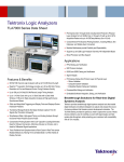
Tektronix Logic Analyzer Family
Quick Start User Manual
www.tektronix.com
071-1575-01
Copyright © Tektronix, Inc. All rights reserved. Licensed software products are owned by Tektronix or its subsidiaries or suppliers, and
are protected by national copyright laws and international treaty provisions.
Tektronix products are covered by U.S. and foreign patents, issued and pending. Information in this publication supersedes that in all
previously published material. Specifications and price change privileges reserved.
TEKTRONIX and TEK are registered trademarks of Tektronix, Inc.
MagniVu is a trademark of Tektronix, Inc.
Contacting Tektronix
Tektronix, Inc.
14200 SW Karl Braun Drive
P.O. Box 500
Beaverton, OR 97077
USA
For product information, sales, service, and technical support:
In North America, call 1-800-833-9200.
Worldwide, visit www.tektronix.com to find contacts in your area.
Warranty 2
Tektronix warrants that this product will be free from defects in materials and workmanship for a period of one (1) year from the date of
shipment. If any such product proves defective during this warranty period, Tektronix, at its option, either will repair the defective
product without charge for parts and labor, or will provide a replacement in exchange for the defective product. Parts, modules and
replacement products used by Tektronix for warranty work may be new or reconditioned to like new performance. All replaced
parts, modules and products become the property of Tektronix.
In order to obtain service under this warranty, Customer must notify Tektronix of the defect before the expiration of the warranty period
and make suitable arrangements for the performance of service. Customer shall be responsible for packaging and shipping the
defective product to the service center designated by Tektronix, with shipping charges prepaid. Tektronix shall pay for the return of the
product to Customer if the shipment is to a location within the country in which the Tektronix service center is located. Customer shall
be responsible for paying all shipping charges, duties, taxes, and any other charges for products returned to any other locations.
This warranty shall not apply to any defect, failure or damage caused by improper use or improper or inadequate maintenance and
care. Tektronix shall not be obligated to furnish service under this warranty a) to repair damage resulting from attempts by personnel
other than Tektronix representatives to install, repair or service the product; b) to repair damage resulting from improper use or
connection to incompatible equipment; c) to repair any damage or malfunction caused by the use of non-Tektronix supplies; or
d) to service a product that has been modified or integrated with other products when the effect of such modification or integration
increases the time or difficulty of servicing the product.
THIS WARRANTY IS GIVEN BY TEKTRONIX WITH RESPECT TO THE PRODUCT IN LIEU OF ANY OTHER WARRANTIES,
EXPRESS OR IMPLIED. TEKTRONIX AND ITS VENDORS DISCLAIM ANY IMPLIED WARRANTIES OF MERCHANTABILITY OR
FITNESS FOR A PARTICULAR PURPOSE. TEKTRONIX’ RESPONSIBILITY TO REPAIR OR REPLACE DEFECTIVE PRODUCTS
IS THE SOLE AND EXCLUSIVE REMEDY PROVIDED TO THE CUSTOMER FOR BREACH OF THIS WARRANTY. TEKTRONIX
AND ITS VENDORS WILL NOT BE LIABLE FOR ANY INDIRECT, SPECIAL, INCIDENTAL, OR CONSEQUENTIAL DAMAGES
IRRESPECTIVE OF WHETHER TEKTRONIX OR THE VENDOR HAS ADVANCE NOTICE OF THE POSSIBILITY OF SUCH
DAMAGES.
Warranty 9(b)
Tektronix warrants that the media on which this software product is furnished and the encoding of the programs on the media will be
free from defects in materials and workmanship for a period of three (3) months from the date of shipment. If any such medium or
encoding proves defective during the warranty period, Tektronix will provide a replacement in exchange for the defective medium.
Except as to the media on which this software product is furnished, this software product is provided “as is” without warranty of any
kind, either express or implied. Tektronix does not warrant that the functions contained in this software product will meet Customer’s
requirements or that the operation of the programs will be uninterrupted or error-free.
In order to obtain service under this warranty, Customer must notify Tektronix of the defect before the expiration of the warranty
period. If Tektronix is unable to provide a replacement that is free from defects in materials and workmanship within a reasonable
time thereafter, Customer may terminate the license for this software product and return this software product and any associated
materials for credit or refund.
THIS WARRANTY IS GIVEN BY TEKTRONIX WITH RESPECT TO THE PRODUCT IN LIEU OF ANY OTHER WARRANTIES,
EXPRESS OR IMPLIED. TEKTRONIX AND ITS VENDORS DISCLAIM ANY IMPLIED WARRANTIES OF MERCHANTABILITY OR
FITNESS FOR A PARTICULAR PURPOSE. TEKTRONIX’ RESPONSIBILITY TO REPLACE DEFECTIVE MEDIA OR REFUND
CUSTOMER’S PAYMENT IS THE SOLE AND EXCLUSIVE REMEDY PROVIDED TO THE CUSTOMER FOR BREACH OF
THIS WARRANTY. TEKTRONIX AND ITS VENDORS WILL NOT BE LIABLE FOR ANY INDIRECT, SPECIAL, INCIDENTAL, OR
CONSEQUENTIAL DAMAGES IRRESPECTIVE OF WHETHER TEKTRONIX OR THE VENDOR HAS ADVANCE NOTICE OF THE
POSSIBILITY OF SUCH DAMAGES.
Table of Contents
Table of Contents
General Safety Summary . .. . .. . .. . .. . .. . .. . .. . .. . .. . .. . .. . .. . .. . .. . .. . .. . .. . .. . .. . .. . .. . .. . .. . .. . .. . .. . .. . .. . .. . .. . .. . .. . .. . .. . .. . . . .
Environmental Considerations . . .. . .. . .. . .. . .. . .. . .. . .. . .. . .. . .. . .. . .. . .. . .. . .. . .. . .. . .. . .. . .. . .. . .. . .. . .. . .. . .. . .. . .. . .. . .. . .. . .. . .. .
Preface .. . .. . .. . .. . .. . .. . .. . .. . .. . .. . .. . .. . .. . .. . .. . .. . .. . .. . .. . .. . .. . .. . .. . .. . .. . .. . .. . .. . .. . .. . .. . .. . .. . .. . .. . .. . .. . .. . .. . .. . .. . .. . .. .
Key Features .. . .. . .. . .. . .. . .. . .. . .. . .. . .. . .. . .. . .. . .. . .. . .. . .. . .. . .. . .. . .. . .. . .. . .. . .. . .. . .. . .. . .. . .. . .. . .. . .. . .. . .. . .. . .. . .. . .. .
Documentation . .. . .. . .. . .. . .. . .. . .. . .. . .. . .. . .. . .. . .. . .. . .. . .. . .. . .. . .. . .. . .. . .. . .. . .. . .. . .. . .. . .. . .. . .. . .. . .. . .. . .. . .. . .. . .. . ..
Version Differences . . .. . .. . .. . .. . .. . .. . .. . .. . .. . .. . .. . .. . .. . .. . .. . .. . .. . .. . .. . .. . .. . .. . .. . .. . .. . .. . .. . .. . .. . .. . .. . .. . .. . .. . .. . ..
Basic Setups .. . .. . .. . .. . .. . .. . .. . .. . .. . .. . .. . .. . .. . .. . .. . .. . .. . .. . .. . .. . .. . .. . .. . .. . .. . .. . .. . .. . .. . .. . .. . .. . .. . .. . .. . .. . .. . .. . .. . .. . .. .
Installation Documentation. .. . .. . .. . .. . .. . .. . .. . .. . .. . .. . .. . .. . .. . .. . .. . .. . .. . .. . .. . .. . .. . .. . .. . .. . .. . .. . .. . .. . .. . .. . .. . .. . .. . .. .
Connecting Probes to the Target System .. . .. . .. . .. . .. . .. . .. . .. . .. . .. . .. . .. . .. . .. . .. . .. . .. . .. . .. . .. . .. . .. . .. . .. . .. . .. . .. . .. . .. .
Navigating the Logic Analyzer Windows . .. . .. . .. . .. . .. . .. . .. . .. . .. . .. . .. . .. . .. . .. . .. . .. . .. . .. . .. . .. . .. . .. . .. . .. . .. . .. . .. . .. . .. .
Basic Steps for Using a Logic Analyzer . . .. . .. . .. . .. . .. . .. . .. . .. . .. . .. . .. . .. . .. . .. . .. . .. . .. . .. . .. . .. . .. . .. . .. . .. . .. . .. . .. . .. . .. .
EasySetup Wizard .. . .. . .. . .. . .. . .. . .. . .. . .. . .. . .. . .. . .. . .. . .. . .. . .. . .. . .. . .. . .. . .. . .. . .. . .. . .. . .. . .. . .. . .. . .. . .. . .. . .. . .. . .. . .. .
Data Window Overview . .. . .. . .. . .. . .. . .. . .. . .. . .. . .. . .. . .. . .. . .. . .. . .. . .. . .. . .. . .. . .. . .. . .. . .. . .. . .. . .. . .. . .. . .. . .. . .. . .. . .. . .. .
Getting Acquainted with Your Instrument .. . .. . .. . .. . .. . .. . .. . .. . .. . .. . .. . .. . .. . .. . .. . .. . .. . .. . .. . .. . .. . .. . .. . .. . .. . .. . .. . .. . .. . .. . .. .
Set the Default System . .. . .. . .. . .. . .. . .. . .. . .. . .. . .. . .. . .. . .. . .. . .. . .. . .. . .. . .. . .. . .. . .. . .. . .. . .. . .. . .. . .. . .. . .. . .. . .. . .. . .. . .. .
Configure the Setup Window . .. . .. . .. . .. . .. . .. . .. . .. . .. . .. . .. . .. . .. . .. . .. . .. . .. . .. . .. . .. . .. . .. . .. . .. . .. . .. . .. . .. . .. . .. . .. . .. . .. .
Define the Trigger Window .. . .. . .. . .. . .. . .. . .. . .. . .. . .. . .. . .. . .. . .. . .. . .. . .. . .. . .. . .. . .. . .. . .. . .. . .. . .. . .. . .. . .. . .. . .. . .. . .. . ..
Define the Waveform Window .. . .. . .. . .. . .. . .. . .. . .. . .. . .. . .. . .. . .. . .. . .. . .. . .. . .. . .. . .. . .. . .. . .. . .. . .. . .. . .. . .. . .. . .. . .. . .. . ..
Acquire Data. .. . .. . .. . .. . .. . .. . .. . .. . .. . .. . .. . .. . .. . .. . .. . .. . .. . .. . .. . .. . .. . .. . .. . .. . .. . .. . .. . .. . .. . .. . .. . .. . .. . .. . .. . .. . .. . .. . . .
Using the Tabbed Trigger Window . .. . .. . .. . .. . .. . .. . .. . .. . .. . .. . .. . .. . .. . .. . .. . .. . .. . .. . .. . .. . .. . .. . .. . .. . .. . .. . .. . .. . .. . .. . ..
Analyzing Data. .. . .. . .. . .. . .. . .. . .. . .. . .. . .. . .. . .. . .. . .. . .. . .. . .. . .. . .. . .. . .. . .. . .. . .. . .. . .. . .. . .. . .. . .. . .. . .. . .. . .. . .. . .. . .. . .. . .. . ..
Zooming Data . . .. . .. . .. . .. . .. . .. . .. . .. . .. . .. . .. . .. . .. . .. . .. . .. . .. . .. . .. . .. . .. . .. . .. . .. . .. . .. . .. . .. . .. . .. . .. . .. . .. . .. . .. . .. . .. . ..
Measure Waveform Data using Cursors . .. . .. . .. . .. . .. . .. . .. . .. . .. . .. . .. . .. . .. . .. . .. . .. . .. . .. . .. . .. . .. . .. . .. . .. . .. . .. . .. . .. . ..
Using the Data Measurement Window .. . .. . .. . .. . .. . .. . .. . .. . .. . .. . .. . .. . .. . .. . .. . .. . .. . .. . .. . .. . .. . .. . .. . .. . .. . .. . .. . .. . .. . ..
View Acquired Data with MagniVu High-Resolution Timing . . .. . .. . .. . .. . .. . .. . .. . .. . .. . .. . .. . .. . .. . .. . .. . .. . .. . .. . .. . .. . .. . ..
Managing Data. .. . .. . .. . .. . .. . .. . .. . .. . .. . .. . .. . .. . .. . .. . .. . .. . .. . .. . .. . .. . .. . .. . .. . .. . .. . .. . .. . .. . .. . .. . .. . .. . .. . .. . .. . .. . .. . .. . .. . ..
Saving Setups . . .. . .. . .. . .. . .. . .. . .. . .. . .. . .. . .. . .. . .. . .. . .. . .. . .. . .. . .. . .. . .. . .. . .. . .. . .. . .. . .. . .. . .. . .. . .. . .. . .. . .. . .. . .. . .. . ..
Loading Setups. .. . .. . .. . .. . .. . .. . .. . .. . .. . .. . .. . .. . .. . .. . .. . .. . .. . .. . .. . .. . .. . .. . .. . .. . .. . .. . .. . .. . .. . .. . .. . .. . .. . .. . .. . .. . .. . ..
iView Integrated Measurements .. . .. . .. . .. . .. . .. . .. . .. . .. . .. . .. . .. . .. . .. . .. . .. . .. . .. . .. . .. . .. . .. . .. . .. . .. . .. . .. . .. . .. . .. . .. . .. . .. . ..
Connecting the Logic Analyzer and the Oscilloscope . . .. . .. . .. . .. . .. . .. . .. . .. . .. . .. . .. . .. . .. . .. . .. . .. . .. . .. . .. . .. . .. . .. . .. . ..
Acquiring the iView Data .. . .. . .. . .. . .. . .. . .. . .. . .. . .. . .. . .. . .. . .. . .. . .. . .. . .. . .. . .. . .. . .. . .. . .. . .. . .. . .. . .. . .. . .. . .. . .. . .. . .. . ..
Aligning the Oscilloscope Data with the Logic Analzyer Data.. . .. . .. . .. . .. . .. . .. . .. . .. . .. . .. . .. . .. . .. . .. . .. . .. . .. . .. . .. . .. . ..
Application Examples.. . .. . .. . .. . .. . .. . .. . .. . .. . .. . .. . .. . .. . .. . .. . .. . .. . .. . .. . .. . .. . .. . .. . .. . .. . .. . .. . .. . .. . .. . .. . .. . .. . .. . .. . .. . .. . ..
Triggering on a Glitch .. . .. . .. . .. . .. . .. . .. . .. . .. . .. . .. . .. . .. . .. . .. . .. . .. . .. . .. . .. . .. . .. . .. . .. . .. . .. . .. . .. . .. . .. . .. . .. . .. . .. . .. . ..
State Acquisition . . .. . .. . .. . .. . .. . .. . .. . .. . .. . .. . .. . .. . .. . .. . .. . .. . .. . .. . .. . .. . .. . .. . .. . .. . .. . .. . .. . .. . .. . .. . .. . .. . .. . .. . .. . .. . ..
Triggering on a Setup & Hold Violation.. . .. . .. . .. . .. . .. . .. . .. . .. . .. . .. . .. . .. . .. . .. . .. . .. . .. . .. . .. . .. . .. . .. . .. . .. . .. . .. . .. . .. . ..
Index
TLA Quick Start User Manual
iii
v
vi
vi
vii
vii
1
1
1
2
3
4
4
5
5
5
10
11
14
15
17
17
18
19
20
22
22
23
23
24
25
26
29
29
32
36
i
Table of Contents
ii
TLA Quick Start User Manual
General Safety Summary
General Safety Summary
Review the following safety precautions to avoid injury and prevent damage to this product or any products connected to it.
To avoid potential hazards, use this product only as specified.
Only qualified personnel should perform service procedures.
While using this product, you may need to access other parts of a larger system. Read the safety sections of the other
component manuals for warnings and cautions related to operating the system.
To Avoid Fire or Personal Injury
Use Proper Power Cord. Use only the power cord specified for this product and certified for the country of use.
Connect and Disconnect Properly. Do not connect or disconnect probes or test leads while they are connected
to a voltage source.
Ground the Product. This product is grounded through the grounding conductor of the power cord. To avoid electric
shock, the grounding conductor must be connected to earth ground. Before making connections to the input or output
terminals of the product, ensure that the product is properly grounded.
Observe All Terminal Ratings. To avoid fire or shock hazard, observe all ratings and markings on the product. Consult
the product manual for further ratings information before making connections to the product.
The inputs are not rated for connection to mains or Category II, III, or IV circuits.
Do not apply a potential to any terminal, including the common terminal, that exceeds the maximum rating of that terminal.
Power Disconnect. The power switch disconnects the product from the power source. See instructions for the location.
Do not block the power switch; it must remain accessible to the user at all times.
Power Disconnect. The power cord disconnects the product from the power source. Do not block the power cord; it
must remain accessible to the user at all times.
Do Not Operate Without Covers. Do not operate this product with covers or panels removed.
Do Not Operate With Suspected Failures. If you suspect that there is damage to this product, have it inspected by
qualified service personnel.
Avoid Exposed Circuitry. Do not touch exposed connections and components when power is present.
Replace Batteries Properly. Replace batteries only with the specified type and rating.
Use Proper Fuse. Use only the fuse type and rating specified for this product.
Do Not Operate in Wet/Damp Conditions.
Do Not Operate in an Explosive Atmosphere.
Keep Product Surfaces Clean and Dry.
Provide Proper Ventilation. Refer to the manual’s installation instructions for details on installing the product so it has
proper ventilation.
TLA Quick Start User Manual
iii
General Safety Summary
Terms in this Manual
These terms may appear in this manual:
WARNING. Warning statements identify conditions or practices that could result in injury or loss of life.
CAUTION. Caution statements identify conditions or practices that could result in damage to this product or other property.
Symbols and Terms on the Product
These terms may appear on the product:
DANGER indicates an injury hazard immediately accessible as you read the marking.
WARNING indicates an injury hazard not immediately accessible as you read the marking.
CAUTION indicates a hazard to property including the product.
The following symbols may appear on the product:
iv
TLA Quick Start User Manual
Environmental Considerations
Environmental Considerations
This section provides information about the environmental impact of the product.
Product End-of-Life Handling
Observe the following guidelines when recycling an instrument or component:
Equipment Recycling. Production of this equipment required the extraction and use of natural resources. The
equipment may contain substances that could be harmful to the environment or human health if improperly handled at the
product’s end of life. In order to avoid release of such substances into the environment and to reduce the use of natural
resources, we encourage you to recycle this product in an appropriate system that will ensure that most of the materials are
reused or recycled appropriately.
The symbol shown below indicates that this product complies with the European Union’s requirements according to Directive
2002/96/EC on waste electrical and electronic equipment (WEEE). For information about recycling options, check the
Support/Service section of the Tektronix Web site (www.tektronix.com).
Mercury Notification. This product uses an LCD backlight lamp that contains mercury. Disposal may be regulated due
to environmental considerations. Please contact your local authorities or, within the United States, the Electronics Industries
Alliance (www.eiae.org) for disposal or recycling information.
Restriction of Hazardous Substances
This product has been classified as Monitoring and Control equipment, and is outside the scope of the 2002/95/EC RoHS
Directive. This product is known to contain lead, cadmium, mercury, and hexavalent chromium.
TLA Quick Start User Manual
v
Preface
Preface
This manual describes the basic operation and concepts of the Tektronix Logic Analyzer series instruments. The TLA5000
Series Logic Analyzers are stand-alone products and the TLA7000 Series Logic Analyzers are configurable modular
products. The TLA7000 Series Logic Analyzers can be configured with a variety of logic analyzer modules and pattern
generator modules. All logic analyzers have integrated operation capabilities with Tektronix TDS oscilloscopes. This
manual supports the following instruments:
TLA5000 Series Logic Analyzers (TLA5201, TLA5202, TLA5203, TLA5204)
TLA7000 Series Mainframes (TLA7012, TLA7016) and their associated modules (TLA7NAx, TLA7Axx, TLA7N4,
TLA7PG2)
Key Features
The Tektronix Logic Analyzers can help you verify and debug hardware designs, processor and bus designs, and embedded
software and hardware integration. Key features include:
34/68/102/136 channel logic analyzers
500 ps (2 GHz) 256 Mb deep timing analysis
125 ps (8 GHz) MagniVu high resolution timing acquisition simultaneous with deep timing or state acquisition to find
difficult problems
Up to 200 MHz state acquisition analysis of synchronous digital circuits, TLA7N4 series
Up to 235 MHz state acquisition analysis of synchronous digital circuits, TLA5000 series
Up to 450 MHz state acquisition analysis of synchronous digital circuits, TLA7NAx series
Up to 800 MHz state acquisition analysis of synchronous digital circuits, TLA7Axx series
Simultaneous state, high-speed timing and analog analysis through the same logic analyzer probe to pin-point elusive
faults without double probing, TLA7Axx series and TDS oscilloscopes
Glitch and setup/hold violation triggering finds and displays elusive hardware problems
Transitional storage extends the signal analysis capture time
Connectorless probing system with 0.5 pF total capacitive loading eliminates the need for on-board connectors,
minimizes intrusion on circuits, and is ideal for differential signal applications
The Tektronix Logic Analyzer family also offers the TLA7PG2 Pattern Generator modules that work with the logic analyzer
modules to generate digital signals to simulate test conditions in software and hardware testing. Key features include:
64 channel modules with up to 2 Mb vector depth and up to 268 MHz clock rate
Support for TTL/CMOS, ECL, PECL/LVPECL, LVDS, and LVCMOS standard logic levels
Variable probes for supporting variable voltage levels and delay of two channels for functional verification
Pattern sequencing control of vector output to allow flexible definition of complex events
vi
TLA Quick Start User Manual
Preface
Documentation
The following table lists related documentation, available on the TLA Documentation CD and on the Tektronix Web site
(www.Tektronix.com).
Related Documentation
Item
Purpose
TLA Quick Start User Manuals
High-level operational overview
Online Help
In-depth operation and UI help
Installation Quick Reference Cards
High-level installation information
Installation Manuals
Detailed first-time installation
information
XYZs of Logic Analyzers
Logic analyzer basics
Application notes
Collection of logic analyzer application
specific notes
TLA Product Specifications &
Performance Verification Procedures
Product specifications and
performance verification procedures
for TLA7000 series products
TPI.NET Documentation
Detailed information for controlling the
logic analyzer using .NET
Field upgrade kits
Upgrade information for your logic
analyzer
Optional Service Manuals
Self-service documentation for
modules and mainframes
Location
Version Differences
Some of the illustrations in this document may have different icons than your instrument due to differences in software
versions. Refer to the online help for specific details of the menu features about your version.
TLA Quick Start User Manual
vii
Preface
viii
TLA Quick Start User Manual
Basic Setups
Basic Setups
Installation Documentation
For installation instructions and descriptions of controls and connectors on your instrument, refer to the installation reference
card or installation manual that came with the instrument. (See page vii, Documentation.)
Connecting Probes to the Target System
The logic analyzer has different methods
of connecting probes to the target system.
Refer to the illustration and connect your
probes to the target system.
Square pin connectors. Use
general-purpose probes to connect
to the target system using square pin
connectors or with square-pin adapters.
Connectorless compression
connectors. Use land pattern probes for
applications that connect many channels
to connectorless compression contacts
on the target system.
Mictor connectors. Use Mictor
connector probes for applications
requiring many channels to be quickly
connected using Mictor connectors or
Mictor adapters.
TLA Quick Start User Manual
1
Basic Setups
Navigating the Logic Analyzer Windows
Tektronix provides several different ways of navigating the logic analyzer windows to accomplish your basic tasks. Choose
the one that works best for you.
TLA Explorer
Use the TLA Explorer to quickly access key windows from a tree structure.
The TLA Explorer shows all of the modules in
the logic analyzer and their sub components.
Toolbar Buttons
Use the toolbar buttons to quickly navigate between key windows while making the best use of screen space.
Click one of the buttons to quickly access the
Setup Window, Trigger Window, Waveform
Window, or the Listing Window for the current
logic analyzer module.
2
TLA Quick Start User Manual
Basic Setups
System Window
Use the icons in the System Window to navigate between windows.
The System Window shows a block diagram
representation of the modules and data
windows available with your logic analyzer.
Click an icon to open the related window.
Quick Tip
Use the front-panel buttons to navigate between windows on the TLA7012 Portable Mainframe.
Basic Steps for Using a Logic Analyzer
The basic steps for using the logic analyzer are summarized below.
1. Use the Setup window to set up the logic analyzer channels, threshold voltages, clocking, and memory depth.
2. Specify triggering in the Trigger window.
3. Configure the Waveform window.
4. Acquire data.
TLA Quick Start User Manual
3
Basic Setups
EasySetup Wizard
The EasySetup Wizard appears when you first power on your instrument (unless it has been disabled). You can use the
EasySetup wizard for initial setups. However, the examples in this document create basic setups without the wizard to help
you learn how to use the instrument on a day-to-day basis.
Data Window Overview
Use data windows to display and analyze data acquired by your instrument. The Waveform and Listing windows are the
default data windows. Create other kinds of data windows using the New Data Window wizard. Refer to the online help for
detailed information on creating and using the various data windows.
Waveform Window
Use Waveform windows to display waveform data from the logic analyzer or from an external oscilloscope. Waveform
windows are best used for diagnosing timing problems, measuring hardware timing-related characteristics, and verifying
correct hardware operation by comparing recorded results against data sheet timing diagrams.
Listing Window
Use Listing windows to display acquired data in a state table display. Listing windows can be used for state machine debug
applications, tracing relative software execution, system optimization, and following data through a system design.
Histogram Window
Use Histogram windows to display acquired data as histograms. Histogram data is useful for evaluating the performance of
software, such as determining which routines or functions take most of the time performing certain tasks.
Source Window
Use Source windows with Listing windows to track the execution of source code in software applications.
Graph Window
Use Graph windows to display the results of acquired data in a graph or chart format.
Protocol Window
Use Protocol windows to display and analyze protocol data.
4
TLA Quick Start User Manual
Getting Acquainted with Your Instrument
Getting Acquainted with Your Instrument
The following sections show how to set up the logic analyzer and to do timing analysis using data from a simple D-type
flip-flop. Flip-flops serve as building blocks in digital systems. Although most flip-flops are buried inside complex ASICS and
other devices, they are useful for showing hardware debugging techniques using a logic analyzer. The examples in this
document use only a few channels to acquire data. However, you can use the same concepts with hundreds of channels.
Set the Default System
Use the default system set up to load the factory default settings.
1. Power on the instrument and wait for
the System window to appear. If the
EasySetup wizard appears, exit the
wizard.
2. Select Default System from the File
menu.
3. Click OK.
Configure the Setup Window
Use the following procedures to define data channels, set the clocking, set the probe threshold voltages, and to use other
features of the Setup window.
Open the Setup Window
Click Setup in the TLA Explorer to open
the Setup window.
TLA Quick Start User Manual
5
Getting Acquainted with Your Instrument
Delete Unused Default Channel Groups
Delete unused channels to focus only on the channels that you need.
1. Position the mouse in the center of the
Setup window, right-click, and select
Delete All Groups.
2. Click Yes when you are prompted to
confirm your action.
6
TLA Quick Start User Manual
Getting Acquainted with Your Instrument
Create New Channel Groups
Channel groups are a collection of probe channels used to accomplish specific tasks. Probe channels are typically organized
from the most significant bit (bit 7) to the least significant bit (bit 0) as shown in the probe channel table. Each probe channel
can have a unique name that appears in the data windows.
1. Enter a unique name for each probe
channel.
For this example, use C for the clock
channel, D for the input, and Q for the
output.
2. Enter a new name for each channel
group.
3. Click the button to the left of the probe
channel name to add the channel.
Repeat for each probe channel that you
want to add to the current group. (This
example has one probe channel per
channel group.)
The order in which you select the
channels is the order the channels will
be displayed.
4. Repeat steps 2 and 3 to create multiple
channel groups (Input and Output in this
example).
Quick Tip
To add all channels of a probe group to a group name, select the group name and click the button to the left of the
probe group, such as A1.
TLA Quick Start User Manual
7
Getting Acquainted with Your Instrument
Set the Memory Depth
Use the memory depth to define the number of data samples to acquire.
Select a memory depth (record length).
The selections vary depending on your
logic analyzer.
Set the Clocking
When you select Internal (asynchronous) clocking, the logic analyzer selects when data is sampled (sample point). Internal
clocking is also known as timing acquisition.
When you use External (synchronous) clocking, the target system specifies the sample point by the external clock. External
clocking is also known as state acquisition.
1. Select Internal.
2. Set the sample period (or use the default
clocking of 2 ns).
Quick Tip
Many clocking selections are available. Refer to the online help for information on other clocking types.
8
TLA Quick Start User Manual
Getting Acquainted with Your Instrument
Check the Probe Activity
1. Click Probes.
The Probe Properties dialog box opens,
showing the probe activity. When the
target system is off, or no probes are
connected, there is no probe activity.
2. Turn on the target system (or connect
the probes). The channels with signal
activity have by up and down arrows.
If there is no probe activity:
Check the probe connections.
Verify that the target system is
powered on.
Check the probe threshold voltages.
Quick Tip
Press the TLA7012 front-panel Activity button to access the Probe Properties dialog box.
TLA Quick Start User Manual
9
Getting Acquainted with Your Instrument
Set the Probe Threshold Voltages
The logic analyzer uses threshold voltages to determine logic levels. The threshold voltage must match the logic family used
on the target system. To change the threshold voltages:
1. Click Thresholds.
2. Enter a threshold voltage.
3. Click Set All to apply the threshold
voltages to all probe inputs.
4. Click Close.
Define the Trigger Window
Use triggers to tell the logic analyzer when to acquire data and display the results in a data window.
1. Click Trigger.
10
TLA Quick Start User Manual
Getting Acquainted with Your Instrument
1. In the Easy Trigger tab, select a trigger
program from the list. For example,
select Trigger immediately to trigger
the instrument on any data.
Use the area below the trigger program
list to enter more details for the trigger
programs, if needed.
2. Click and drag the Trigger Pos indicator
to the point in memory where you want
the instrument to trigger. The default
selection is 50%.
Quick Tips
After you have acquired data, use the Tabbed Trigger window to define simple trigger programs without having to close
the Waveform or Listing window.
Use EasyTrigger to define the trigger program for most applications; use PowerTrigger to customize the trigger program
for specific needs.
Define the Waveform Window
Default Waveform and Listing windows are provided for you. For most applications, you will define the data windows for your
needs. For this example, you will use the Waveform window.
Open the Waveform Window
Click Waveform 1.
TLA Quick Start User Manual
11
Getting Acquainted with Your Instrument
Delete the Default Waveforms
1. Press the CTRL key and select each
waveform name that you want to delete.
2. Right-click and select Delete
Waveforms.
12
TLA Quick Start User Manual
Getting Acquainted with Your Instrument
Add Waveforms
Use the following steps to add the waveforms that you defined in the Setup window. (See page 7, Create New Channel
Groups.)
1. Right-click in the waveform label area
and select Add Waveform.
2. Expand each channel group.
TLA Quick Start User Manual
13
Getting Acquainted with Your Instrument
3. Press the Ctrl key while selecting each
channel that you want to add to the
Waveform window.
4. Click Add.
5. Click Close.
Quick Tip
Select By Name to add the probe channels to the Waveform window by their channel names. This is useful for groups
that have only one channel.
Acquire Data
After you have defined all of the setups and connected the probes to the target system, you are ready to acquire data. You
can acquire a single sequence of data, or you can continuously acquire data.
Making a Single Acquisition
1. Click Run.
The Run button changes to Stop until the
instrument has met the trigger conditions
and has acquired the data. The button
changes back to Run after data has been
acquired.
2. If the instrument does not trigger, click
Status. Use the information in the dialog
box to see if the logic analyzer is waiting
for the trigger or if it has triggered and is
filling its acquisition memory.
When a trigger occurs, the instrument
displays the flip-flop Clock, Input, and
Output data in the Waveform window.
The trigger point is represented by the
red trigger marker (T).
14
TLA Quick Start User Manual
Getting Acquainted with Your Instrument
Quick Tip
To verify that the instrument is acquiring data during long periods of inactivity on the screen, check that the Tek icon in
the upper right corner of the screen is animated.
Making Repetitive Acquisitions
1. Click the Repetitive Run button to acquire
data repetitively. The icon changes from
an arrow to a loop.
2. Click Run. The instrument will acquire
data until you click Stop or until you
click the Repetitive Run button again to
change back to single run mode.
Using the Tabbed Trigger Window
You can define a trigger program using the Tabbed Trigger window without closing the Waveform or Listing window. The
following example shows how to set up the instrument to trigger on a channel edge.
You can also use this procedure to quickly define other trigger programs. To acquire complex data, you can still use
the Power Trigger window.
1. Click Run.
Data must be present before you can use the
Tabbed Trigger window.
2. Click Trigger in the tabbed window.
TLA Quick Start User Manual
15
Getting Acquainted with Your Instrument
3. Click and drag the Channel Edge icon
from the Tabbed Trigger window to the
Output waveform (channel).
The instrument will display the details of
the program in the Trigger Details area.
The details are similar to those in the
Power Trigger window. You can edit any
of the details.
4. Click Run to acquire data and trigger
the instrument based on the new trigger
program.
16
TLA Quick Start User Manual
Analyzing Data
Analyzing Data
Your instrument has several tools for analyzing data, such as zooming data, measuring data, and viewing data with MagniVu
high-resolution timing. This section provides concepts and procedures for analyzing data in the Waveform window. Some of
these features also apply to the Listing window; refer to the online help for more details.
Zooming Data
To zoom data in the Waveform window:
1. Click and drag from left to right over the
area you want to zoom.
2. Click the Zoom In button a few times to
zoom the timing data samples.
Quick Tips
Click and drag from the right to the left to zoom to the previous selection.
Use the Zoom In and the Zoom Out buttons in the toolbar as an alternative method of zooming data.
TLA Quick Start User Manual
17
Analyzing Data
Measure Waveform Data using Cursors
Use the Snap to Edge feature with cursors in the Waveform window to measure the time between waveforms.
1. Point the mouse at Cursor 1 over the
waveform that you want to measure.
2. Click and drag Cursor 1 toward a leading
or trailing edge of the waveform.
3. Release the mouse to snap the cursor to
the next waveform edge.
4. Repeat for Cursor 2.
5. If the Delta-time toolbar is turned off,
click
.
6. Read the time difference between the
two cursors.
18
TLA Quick Start User Manual
Analyzing Data
Quick Tips
If the cursors do not appear in the Waveform window, use the right-click menu to move the cursors on screen (select
Move Cursor 1 Here).
You can use the Snap to Edge feature with any of the user marks.
You can click
to add multiple Delta-Time toolbars in the same Waveform window.
You can use the Delta-Time toolbar to measure time between any two marks. Select the marks from the drop-down
lists in the toolbar.
Using the Data Measurement Window
Use the Data Measurement window to quickly take measurements in the Waveform or Listing window.
1. Click Measurements.
2. Click and drag the Period icon to the
Clock waveform, and release.
The selected measurement will be added
to the Data Measurement window at the
bottom of the display.
3. Repeat for any other measurements.
4. Click the Statistics tab in the Data
Measurement window to display the
results of the measurement along with
other statistics. Measurements are taken
on the existing data without having to
acquire new data.
TLA Quick Start User Manual
19
Analyzing Data
Quick Tips
To take a measurement on new data, click Run.
To save the measurement data to a file, click the Export button in the Statistics tab of the Data Measurement window.
To select a measurement in the Waveform window, select the waveform label, right-click the waveform, select Add LA
Data Measurement, and then select a measurement from the list.
View Acquired Data with MagniVu High-Resolution Timing
MagniVu high-resolution timing provides 125 ps sampling (500 ps sampling on TLA7N4 modules) on all waveforms to analyze
details that you may not see using Deep timing. It is like having two logic analyzers in one. Using a single probe you can view
Deep timing data for long time spans and MagniVu high-resolution timing data for greater resolution at the area of interest.
The MagniVu high-resolution data is automatically acquired with each acquisition. However, the waveforms may not be
visible. To add MagniVu timing waveforms:
1. Click below the waveform labels to
deselect all waveforms.
2. Click MagniVu to add the MagniVu data
to the Waveform window.
The MagniVu timing waveforms are
added to the window in a different color.
20
TLA Quick Start User Manual
Analyzing Data
3. Click the Zoom Out button until you see
the entire MagniVu timing waveforms.
Note that the MagniVu timing data is 16
K bits long as compared to the Deep
timing data. Deep timing lets you acquire
a large amount of data; MagniVu timing
lets you focus on the details of the data.
4. Move Cursor 1 to an area in the
Waveform window outside the range of
the MagniVu data.
5. Zoom on Cursor 1. The MagniVu button
indicates the MagniVu waveforms are
off screen.
6. Click the MagniVu button to center the
MagniVu data on-screen.
TLA Quick Start User Manual
21
Managing Data
Quick Tip
Click the MagniVu button in the Listing or Waveform window to turn the MagniVu display on and off.
Managing Data
This section contains procedures for managing data, such as saving setups and loading saved setups.
Saving Setups
After defining your setup, you can save it for future use.
1. Select Save System As.
2. Select one of the following save options:
Save all Acquired Data
Save only Unsuppressed Data
Don’t Save Acquired Data
3. Enter a file name.
4. Click Save.
Quick Tips
Save often to avoid losing critical setups and data.
See the online help for details on saving setups.
22
TLA Quick Start User Manual
iView Integrated Measurements
Loading Setups
Use the following steps to load the setup that you saved under Getting Acquainted with Your Instrument. (See page 5.)
1. Select Load System.
2. Select the file name.
3. Click Open.
4. Click Yes when you are prompted to
confirm your actions.
iView Integrated Measurements
You can use the iView feature to connect an external Tektronix oscilloscope to the logic analyzer, acquire data from both
instruments, and display the results on the logic analyzer. This is useful for displaying the analog components of a signal in
the same data window as the digital components.
In the following examples the logic analyzer and the oscilloscope will acquire the same data. The logic analyzer captures
the digital components and the oscilloscope captures the analog components.
Use the following steps to set up the oscilloscope for these examples. Refer to the documentation that came with your
oscilloscope for operating instructions.
1. Connect the oscilloscope probe to the same signal source as the logic analyzer (for this example, connect to the
Q output of the flipflop).
2. Power on the oscilloscope.
3. Press the Default Setup button on the oscilloscope, and then press the Autoset button. You should have a signal on
the oscilloscope screen.
TLA Quick Start User Manual
23
iView Integrated Measurements
Connecting the Logic Analyzer and the Oscilloscope
After completing the oscilloscope and logic analyzer setups, use the iView wizard to connect the two instruments together.
1. From the logic analyzer System
menu, select Add iView External
Oscilloscope . . . .
2. Follow the instructions on each page
of the iView wizard to do the following
steps:
Select the oscilloscope.
Connect the iView cable to the logic
analyzer.
Connect the iView cable to the
oscilloscope.
Verify the GPIB address of the
oscilloscope.
Identify where to display the
oscilloscope data.
Specify the triggering.
Verify the connections and setups.
3. Click Finish on the last page of the
wizard.
Quick Tips
Start the iView wizard by clicking the iView icon in the Listing window or Waveform window. If you have a TLA7012
Portable Mainframe, start the iView wizard by pressing the front-panel iView button.
If the oscilloscope is properly connected to the logic analyzer when you start the iView wizard, the wizard will bypass
the connection instructions. Follow the on-screen instructions to finish the installation or to return to the start page of
the wizard.
24
TLA Quick Start User Manual
iView Integrated Measurements
The oscilloscope is added to the TLA
Explorer and to the System window.
Acquiring the iView Data
The next steps consist of acquiring the initial data, and then adjusting the data to properly view and analyze the data.
Acquire the Initial Data
1. Click MagniView to turn on the MagniVu
waveforms.
2. Click iView to turn on the iView
waveforms.
If desired, delete any of the unused
oscilloscope waveforms.
3. Click Run to acquire and display
waveform data from both instruments.
Depending on the oscilloscope and your
Waveform window settings, you may
not see any waveform data from the
oscilloscope. If necessary, click the iView
button in the Waveform window to bring
the waveform on screen.
TLA Quick Start User Manual
25
iView Integrated Measurements
Aligning the Oscilloscope Data with the Logic Analzyer Data
Complete the following steps to fine-tune the data alignment.
1. Zoom the display to measure the
time difference between the glitch in
the MagniVu waveform and in the
oscilloscope waveform:
2. Move Cursor 1 to the leading edge of the
glitch in the MagniVu waveform.
3. Click the oscilloscope waveform label
to allow you to read the voltage
measurements.
If the highlighted waveform is too bright,
click the area below the waveform labels
to turn the highlighting off (you may need
to resize the Waveform window to show
the label area with no labels).
4. Move Cursor 2 to the point on the
glitch where the waveform crosses the
threshold voltage as indicated by the
measurement readout.
5. Note the Delta Time value.
26
TLA Quick Start User Manual
iView Integrated Measurements
6. Select Time Alignment . . . from the
Data menu.
7. Select the oscilloscope as the data
source.
8. Enter the offset value (Delta Time value)
into the Adjust time offset box.
9. Click OK.
TLA Quick Start User Manual
27
iView Integrated Measurements
The oscilloscope data is now time-aligned
with the logic analyzer data.
Quick Tips
A positive Adjust Time offset value will move the oscilloscope waveform in the display to the right with respect to the logic
analyzer data. A negative offset value will move the oscilloscope waveform to the left.
Click the iView button in the Waveform window or press iView button on the TLA7012 front panel to turn the iView
signals on and off.
28
TLA Quick Start User Manual
Application Examples
Application Examples
The examples in this section show how to use your instrument to do common logic analyzer tasks. These examples use the
basic setups with the flip-flop examples developed earlier in this document. (See page 5, Getting Acquainted with Your
Instrument.) Refer to the setups as needed to step through the application examples.
Triggering on a Glitch
Logic analyzers are useful for debugging elusive, intermittent problems, such as glitches. Use the following procedures to set
up the logic analyzer to trigger on a glitch.
Set up the Glitch Trigger
1. Configure the Setup window and ensure
that the Clocking is set to Internal. (See
page 5, Configure the Setup Window.)
2. Open the Waveform window, right-click
in the waveform label area, and select
Add Waveform . . ..
3. Select the Channel groups (Clock, Input,
and Output for this example).
4. Click Add.
5. Click Close.
TLA Quick Start User Manual
29
Application Examples
6. Click Run.
7. Click Trigger.
8. Click and drag the Glitch icon from the
Tabbed Trigger window to the Output
group waveform.
30
TLA Quick Start User Manual
Application Examples
9. Select the groups that you want the logic
analyzer to trigger on. Clear any other
channels.
The channel where you dropped the
Glitch icon is selected by default. You
can select the groups you want and avoid
triggering on channels that may contain
glitches that you don’t care about.
10. Click Run.
11. Expand the Output group to see the
highlighted glitch on the Q waveform.
12. Click MagniVu.
The glitch data is highlighted in red at
every sample point for each channel
in the Deep timing waveforms. The
MagniVu timing waveforms show the
high-resolution glitch data.
TLA Quick Start User Manual
31
Application Examples
State Acquisition
You can use the logic analyzer for state data analysis; you can view the data in tabular form in the Listing window.
Define the Setup Window
State acquisition uses an external clock from the target system to tell the logic analyzer when to sample data.
1. Configure the channels in the Setup
window. (See page 5, Configure the
Setup Window.)
2. Change the clocking to External.
3. Select Normal.
4. Click More to define the external
clocking.
5. Select the rising edge of CK0().
6. Click Close.
32
TLA Quick Start User Manual
Application Examples
Configure the Trigger
1. Define the setups for the Waveform
window. (See page 11, Define the
Waveform Window.)
You will use the Waveform window
setups to help define the trigger.
2. Click Trigger in the tabbed window.
3. Click and drag the Channel Edge icon
from the Tabbed Trigger window to the
Output waveform.
Acquire Data
1. Click Run.
2. Zoom the data as necessary to view the
acquired data.
The LA1: Clock(0) waveform data
shows no changes because the data
is sampled on each rising clock edge.
Each tic mark of the Sample clock
waveform represents a clock edge.
The MagniVu high-resolution data
still displays timing data.
TLA Quick Start User Manual
33
Application Examples
Configure the Listing Window
1. Click the Listing window icon in the TLA
explorer.
The listing window has no data in it. You
need to add the data columns to the
window to see the data.
2. Right-click in the data area and select
Add Column.
34
TLA Quick Start User Manual
Application Examples
3. Expand the channel groups, press the
Ctrl key while selecting each column,
and click Add to add the columns to the
Listing window.
4. Click Close.
5. Click and drag the Timestamp column to
the right of the last column. Timestamps
may be easier to read in this position.
Note the data in the Listing window.
The clock data appears as zeros
because the data is sampled on the
rising edge of the clock.
The Input and Output data appear as
ones and zeros.
The Timestamp column lists the time
between data samples.
The trigger point is halfway through the
data because the Trigger position was
set to 50%.
TLA Quick Start User Manual
35
Application Examples
Triggering on a Setup & Hold Violation
Use the Setup & Hold triggering to capture setup and hold violations. This example uses the same setups for the Setup
window as the previous example. (See page 32, State Acquisition.)
Define the Setup Window
1. Configure the channels in the Setup
window. (See page 5, Configure the
Setup Window.)
2. Change the clocking to External.
3. Select Normal.
4. Click More to define the external
clocking.
5. Select the rising edge of CK0().
6. Click Close.
36
TLA Quick Start User Manual
Application Examples
Configure the Trigger
1. Click Run.
2. Click Trigger.
3. Click and drag the Setup and Hold icon
from the Tabbed Trigger window to the
Input waveform.
4. Select the desired value for the Input
group/channel setup time (3 ns in this
example).
5. Select the desired hold time (1 ns in this
example).
TLA Quick Start User Manual
37
Application Examples
Acquire and Measure the MagniVu High-Resolution Timing Data
1. Click Run.
2. View the data in the Waveform window.
The instrument triggers on the rising
edge of the clock signal at the violation.
The setup and hold violation area is
highlighted in red for each setup and hold
violation on the Deep timing waveform.
Use the MagniVu timing to view and
measure the actual details.
3. Zoom the data as necessary to see the
MagniVu waveforms.
4. Select System Trigger in the
Measurement toolbar.
5. Move Cursor 2 to the data input
transition.
6. Read the setup time from the Delta-Time
readout.
38
TLA Quick Start User Manual
Index
Index
A
L
Acquiring data, 14
iView, 25
Adding an external oscilloscope, 24
Listing window, 4
adding columns, 34
moving columns, 35
opening, 34
Loading setups, 23
Setups
loading, 23
saving, 22
Snap to Edge, 18
State acquisition, 32
System Window, 3
Basic steps, 3
M
T
C
MagniVu button, 20
MagniVu timing, 20
viewing setup and hold
violations, 38
Measuring data, 18
Memory depth
setting, 8
B
Channel groups
creating, 7
deleting, 6
naming, 7
Clocking
asynchronous, 8
setting, 8
synchronous, 8
Connecting
probes, 1
Cursors
measuring data, 18
D
Data Measurement window, 19
Data windows, 4
Default system, 5
Delta-Time toolbar, 19
Documentation, vii
Drag and drop measurements, 19
E
Easy Setup wizard, 4
G
O
Opening
Listing window, 34
Setup window, 5
Trigger window, 10
Waveform window, 11
P
Probe
activity, 9
connections, 1
threshold voltages, 10
R
Record length, 8
, See also Memory depth
Related documentation, vii
Run/Stop button, 14
Glitch triggering, 29
S
I
Safety Summary, iii
Saving setups, 22
Setup window
clocking, 8
opening, 5
setting memory depth, 8
Instrument setups, 1
iView, 23
aligning data, 26
iView wizard, 24
TLA Quick Start User Manual
Target system
connections, 1
TLA Explorer, 2
Toolbar Buttons, 2
Trigger
defining, 10
page, 15
Triggering
glitch, 29
setup and hold, 36
U
Using the logic analyzer, 3
W
Waveform window, 4
opening, 11
Waveforms
adding, 13
deleting, 12
Windows
Listing, 4, 34
Waveform, 4
opening, 11
Z
Zooming data, 17
39