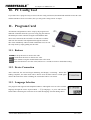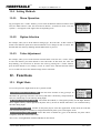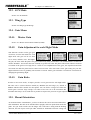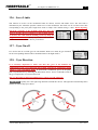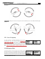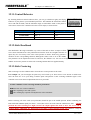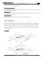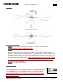
1
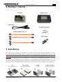
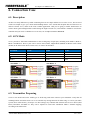
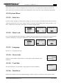
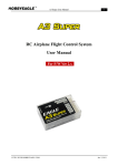
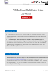
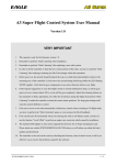
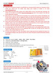
A3 Super User Manual Ver.2.7 1 RC Airplane Flight Control System User Manual F/W Ver 2.7 HTTP://WWW.HOBBYEAGLE.COM Jul. 5, 2014 A3 Super User Manual Ver.2.7 2 VERY IMPORTANT! 1 This manual is written only for firmware Ver.2.7. 2 Always choose a reliable BEC or ESC to provide a stable operating voltage for the controller. The BEC should have sufficient capacity to provide working current for all the electronic devices on the plane especially when using several high torque servos. 3 When using the A3 Super in your plane and wanting the best performance possible from it, you may want to consider using high speed digital servos. 4 The controller needs to perform a gyro calibration every time it starts, don’t move the plane while the LED blinking WHITE very rapidly after power on, this will take you about 2 seconds. 5 After gyro calibration, an automatic stick centering will be performed immediately. Put all the sticks (except throttle) in their middle positions and don’t move them until initialization is done. The LED will keep flashing GREEN rapidly for about 1 second when stick centering is being performed. 6 It is extremely important to make sure that the gyros are compensating in the correct direction after installation, otherwise it could lead to losing control or even crash during flight! 7 Such functions as End-Point, D/R or EXP of the radio system can be used as usual according to your preferences. But please let them stay at default during installation. 8 Always disable any mixing functions for delta-wing or v-tail in your radio system, these will be done by A3 Super. 9 Following the suggestions on your first flight: Switch to normal stabilization mode, set all the gyro gain to a lower volume (about 30%), or turn off the gyro completely. Adjust the trimming buttons on the transmitter to find a appropriate zero offset for all surfaces during the flight. Next land the plane, turn off the power and then restart the A3 Super to re-initialize the gyros so it can re-learn the new center positions that were made during the test flight. Or perform a stick centering to make the controller re-learn the current center positions. Usually you just need a small gain settings when operating it in self-balance mode, a large gain may probably make the plane difficult to control. We would strongly recommend that you use the remote master gain control to make it much more convenient for gain adjusting during the flight. 10 The included USB adapter is only used to upgrade the firmware for A3 Super and program card. Please check our website WWW.HOBBYEAGLE.COM where we will inform you about the latest updates and downloads. 11 The controller or the card can be reset by refreshing the firmware, when it doesn't work, it will be an effective way to resolve the problems caused by the software. HTTP://WWW.HOBBYEAGLE.COM Jul. 5, 2014 A3 Super User Manual Ver.2.7 3 1. Introduction A3 Super is the latest RC flight control system of EAGLE’s A3 Series. It is designed especially for fixed-wing. With an integrated built-in high precision 6-axis (3 gyro + 3 acc) MEMS sensor and advanced attitude and PID control algorithm, the controller can accurately detect the angular velocity and attitude of the plane and issue commands to all servos, which enables the balance and stability throughout the flight. A3 Super provides features of delta-wing (flying-wing), v-tail, remote master gain adjustment and separate dual aileron and elevator control. It can be used in nearly any type of RC planes. A3 Super offers four flight modes, including Normal Stabilization Mode, 3D Attitude Locking Mode, Self-balance Mode and Gyro Deactivated Mode. It also provides three kinds of control behavior including Stable Mode, Normal Mode and Sport Mode to meet the need of various user’s requirement. We also provide you a program card. Without connecting to a PC, you can easily setup all the functions and parameters even in the outdoor flight. The firmware can be upgraded through the USB adapter. Please check out our website WWW.HOBBYEAGLE.COM for the latest updates and downloads. 2. Features Integrated design of 6-axis (3 gyro+3 acc ) MEMS sensor for self-stability and self-balance. Advanced brown-out fast recovery ability provides you better security and reliability. 4 flight modes: Normal Stabilization, 3D Attitude Locking, Self-balance and Gyro Deactivated Modes. 4 AUX modes to define functional combination of input pins. 3 control behaviors: stable, normal and sport modes. 5 operating frequencies for servos, compatible with analog or digital servos. Remote master gain adjustment during flight. Separate dual aileron and elevator with dual input supported. Independent gyro direction setup for aileron 2 and elevator 2. Easy-to-use program card which supports both Simplified Chinese and English. Independent gyro gain adjustment and gyro ratio selection for each flight mode. Separate adjustments for servo travel limits. Mixing functions of delta-wing (flying-wing) and v-tail. More advanced settings such as gyro response rate, gyro switch, level offset, stick centering and stick dead band etc. 3. Specifications Gyroscope: ±2000 dps Accelerometer: ±4g Input Voltage: DC5V~6V Supported Servo Type: 1520μs analog and digital servo Operating Temperature: -40 ℃ ~ 85 ℃ Size: 43×27mm Weight: 10g (excluding wires) HTTP://WWW.HOBBYEAGLE.COM Jul. 5, 2014 A3 Super User Manual Ver.2.7 4 4. Package Contents 5. Installation The controller must be mounted on the platform of the airframe by using one of the provided double-sided tapes. It can be attached flat or upright, and even upside down under the plane. You just need to make sure the longer side of the unit is along with the heading direction, the side of pins can be put either forwards or backwards. The illustration shows you 4 different mount orientations. After installation, remember to choose the correct setting in the program card or PC config tool . As the controller is designed for balancing, please make sure that the mounting platform should be parallel to the horizon and locate the controller as close to the CG as possible. In order to offset the deviation of installation you need to perform a level calibration after installation. HTTP://WWW.HOBBYEAGLE.COM Jul. 5, 2014 A3 Super User Manual Ver.2.7 5 6. Connection Case 6.1. Description As there are many different ways while connecting between A3 Super and the receiver since ver.2.x, here we need to take an example to give you a better understanding about it. Let's assume that the plane has two aileron servos and one elevator servo, which is the most common application. And you are going to enable both features of remote master gain and flight mode switch during the flight. In such case, AUX Mode-3 should be used for the controller and you need a 7-channel receiver at least, for example FUTABA's R6008HS. 6.2. AUX Mode Ver.2.1 provides 4 functional combinations for the second group of input pins, including AUX Mode-1, Mode-2, Mode-3 and Mode-4. These 3 pins can be used as AIL2, ELE2, Flight Mode (FMOD) or Master Gain Control (GAIN) as the chart below shows. In this case, we choose AUX mode-3. AUX Mode Mode-1 AUX3 FMOD AUX2 ELE2 AUX1 AIL2 Mode-2 GAIN ELE2 AIL2 √ Mode-3 FMOD GAIN AIL2 Mode-4 FMOD GAIN ELE2 6.3. Transmitter Preparing Create a new model and set the model type as fixed-wing with 2AIL+1ELE in your transmitter. Verify that all trimming buttons and sub-trims are set to 0%. Disable any mixing functions for delta-wing or v-tail in your radio system, these will be done by A3 Super. Let other settings stay at default this moment such as Servo Travel (End Point), Dual Rate and EXP etc. They can be adjusted as usual after installation. Make a channel mapping according to the table below: HTTP://WWW.HOBBYEAGLE.COM Jul. 5, 2014 A3 Super User Manual Ver.2.7 6 CH1 CH2 CH3 CH4 CH5 CH6 CH7 Aileron Elevator Throttle Rudder Flight Mode Aileron 2 Master Gain A 3-position switch (SE) is assigned to channel-5 for flight mode switching, which is implemented by using the GEAR function in the radio system. A knob (RD) is assigned to channel-7 for the adjustment of master gain, surely you might use a 3-position switch instead to get a 3-level gain control if you like. 6.4. Wiring Connect all the required channels between the controller and the receiver, using the included plain 3-wire cables, which have only one lead of the control signal on the receiver side, and are connected to the controller on the combined connector. The controller requires at least 3 receiver channels, up to 7 channels. The channels of AIL, ELE and RUD must be connected all the time otherwise the controller will not work. The other 3 pins should be connected according to the AUX mode currently selected. The throttle servo or ESC is connected as normal to the throttle channel of the receiver without bridging the controller. The illustration below shows the wiring method only for AUX Mode-3, which is used in this case. HTTP://WWW.HOBBYEAGLE.COM Jul. 5, 2014 A3 Super User Manual Ver.2.7 7 6.5. Power Supply The controller is powered through the [BATT] pins. To achieve it, you can connect it directly to any idle channel of the receiver using the included 3-wire receiver cable, or to an independent BEC. The voltage range is 5 to 6V. If a BEC is used as the power supply, please make sure that the voltage not exceeding the working voltage permit of your servos, and verify that the BEC have sufficient capacity to provide working current for all the electronic devices on the plane especially when using several high torque servos. 6.6. Flight Mode Channel (FMOD) [FMOD] is used for switching the flight mode. We have assigned a 3-position switch to it as mentioned above. The expected flight mode can be preset in the function "Flight Mode" of the program card or config tool. System will default to the mode which assigned to position-1 if you leave this pin unconnected. Even so, it is recommended that you always use an Position-1 Position-2 Position-3 independent channel to switch the 1020-1320μs 1320~1720μs 1720-2020μs Pulse Width mode in flight. Normal Mode 3D Mode Self-balance Default 6.7. Master Gain Control Channel (GAIN) [GAIN] is used to control the master gain remotely. In this case, we use a knob (RD) to make a linear adjustment of the gain. Surely a 3-position switch can be used instead to get a 3-level gain control.. Once connected, the master gain will be controlled by the transmitter directly. Only when the pin is disabled or unconnected, the master gain can be modified via the program card or config tool. 6.8. Dual Aileron & Dual Elevator A true dual aileron and elevator system is available now on A3 Super, the OUT4 is for the 2nd aileron servo and the OUT5 is for the 2nd elevator servo. Mostly we use two aileron servos with single aileron input, in this condition, you just need to plug the two aileron servos into OUT1 and OUT4 respectively. The OUT4 will become a mirror of OUT1 by the software automatically, which can avoid the hassle using a Y-extension cable. This is very similar in connecting the dual elevator. The dual channels share the same settings, such as servo limits, gyro direction and gain setting and so on. For example, if you set the servo limits of aileron channel to ±80%, the maximum travel of both aileron servos will be ±80%. Usually the 2 servos should be installed symmetrically on the both side of the wing, but you can make them in an opposite direction if you like. The separate gyro reversing for AIL2 and ELE2 will help you get the correct result. HTTP://WWW.HOBBYEAGLE.COM Jul. 5, 2014 A3 Super User Manual Ver.2.7 8 6.9. Wing Type & Mixing A3 Super has already built in such mixing functions as delta-wing (flying-wing) and v-tail. When operating it in such modes, the corresponding mixing must be disabled within your transmitter. All you need is to set your radio to a single 4-channel fixed-wing mode. Connect the servos by following the illustration shown. HTTP://WWW.HOBBYEAGLE.COM Jul. 5, 2014 A3 Super User Manual Ver.2.7 9 7. Brown-out Fast Recovery The recommended operating voltage of A3 Super is 5~6V. The controller will perform a protective reset when an unforeseen power failure occurs such as a voltage drop (< 2.7V) or interruption of the BEC. It will take several seconds in normal startup process because of the self-test and gyro calibration, which will be unacceptable during flight. This function is used to handle such emergency situations. When an unexpected reboot happens, the controller will perform a fast startup and resume working very quickly by skipping the self-test and gyro calibration to ensure the safety of your plane. But even so, the most important issue is that you should always choose a reliable BEC for your plane! 8. LED Indicator A RGB LED indicator is used for working status display and error report, shown below: Condition Power On Operating Others Color Description White, 2 Seconds Ready to start initialization. White, Fast Flashing Gyro calibrating, don't move the plane! White, 1 Flash Initialize success. Red, Fast Flashing Initialize failed, please retry. Red, Slow Flashing No signal checked, you must get AIL, ELE and RUD connected. Solid Red Gyro deactivated mode, ready for flight. Solid Blue Normal stabilization mode, ready for flight. Solid Violet 3D flight mode, ready for flight. Solid White Self-balance mode, ready for flight. Green, Fast Flashing Stick centering, don’t move the sticks! Yellow, Fast Flashing Level calibrating, don’t move the plane and keep it level! 9. Start Up Steps To achieve the best performance, please follow the steps below before every flight: Step 1 Turn on the transmitter and put all the sticks in the middle position (except throttle). Step 2 Put the plane on the ground and keep it stationary. Step 3 Power on the plane, the LED will turn WHITE for about 2 seconds then begin to flash rapidly (about 2seconds), which means the gyro is calibrating, don’t move the plane during this moment. After successful initialization the LED will flash WHITE once. If the LED keeps flashing RED rapidly, you have to cut off the power and retry. Then the LED will begin to flash GREEN rapidly (about 1 second) which means the stick centering is being performing, don’t move the sticks until the calibration is done. Step 4 After initialization, the color of the LED will show you that which flight mode is currently selected. Don't forget to move the sticks and check if the servos move in the correct direction before every flight. HTTP://WWW.HOBBYEAGLE.COM Jul. 5, 2014 A3 Super User Manual Ver.2.7 10 10. PC Config Tool If you don’t have a program card you can use the PC config tool instead, download and install the newest PC suite and the USB driver from our website, then you will get the config tool for A3 Super. 11. Program Card All functions and parameters can be setup by the program card. When the controller shows the system is ready, plug the card into the DATA port on the controller using the included black data cable. Once connected, the card will be on and start to read the data from the controller. The adjustment through the card will take effect immediately without a final confirmation. You can exit the setup mode by simply pulling out the cable. 11.1. Buttons UP/+ Scroll up the menu or increase the value. DN/- Scroll down the menu or decrease the value. ESC Exit without saving the modified and return to the menu. ENT Enter the function or save the value, hold it over 2 seconds to restore to the default setting. 11.2. Device Connection After connected, the card will begin initializing and display: Connecting... When data loading completes, the main menu will be shown. Press the ESC button to reload again when in the main menu. After reloading, the current data will be overwritten. 11.3. Language Selection The program card supports both Simplified Chinese and English. You can select suitable language through the menu "System Menu -> 语言/Language", or press and hold the button while connecting the card to the device until the language selection dialog shows. HTTP://WWW.HOBBYEAGLE.COM Jul. 5, 2014 A3 Super User Manual Ver.2.7 11 11.4. Setting Methods 11.4.1. Menu Operation By pressing the UP/+ or DN/- buttons, you can select the different functions within a menu. Press the ENT button to enter the selected item. When a second-level menu exists, the symbol ">" will appear on the right of the corresponding items. 11.4.2. Option Selection For example, when you are in the function "Wing Type". Press the UP/+ or DN/- button to switch to the different option. Press the ENT button to save changes or ESC to cancel. The unconfirmed item will keep flashing until the ENT button is pressed. 11.4.3. Value Adjustment For example, when you are in the function "Normal Gain". Press the UP/+ or DN/- button to select the channel, press ENT button to enter edit mode. In edit mode, the value will keep flashing, you can increase or decrease the value by pressing UP/+ or DN/- buttons, press the ENT button to save changes or ESC to cancel. Press and hold the ENT button over 2 seconds can restore the default settings when in edit mode. 12. Functions 12.1. Flight Mode It is used to preset the flight mode for the 3-position switch. Normal Stabilization Mode (NORM) The most basic function of the gyroscope. In this mode, the gyroscope will sense roll velocity and make a momentary compensation for each axis, which improves the stability during flight. 3D Attitude Locking Mode (3DAL) Also called AVCS Mode, it is designed especially for 3D flight. With the active angular velocity control algorithm, the plane will try to lock its attitude when there is no command sent by the radio during flight. Self-balance Mode (SBAL) Suitable for the junior players or the FPV application. In this mode, the controller will command the plane to maintain level flight automatically when you're releasing the sticks. Gyro Deactivated Mode (DACT) Choose this mode to disable the gyros of all channels, the plane will be completely under the control of the radio. Also see P7 "6.6.Flight Mode Channel (FMOD) for more detail. HTTP://WWW.HOBBYEAGLE.COM Jul. 5, 2014 A3 Super User Manual Ver.2.7 12 12.2. AUX Mode See P5 "6.2.AUX Mode". 12.3. Wing Type See P8 "6.9.Wing Type & Mixing". 12.4. Gain Menu 12.4.1. Master Gain See P7 "6.7. Master Gain Control Channel (GAIN)". 12.4.2. Gain Adjustment for each Flight Mode This function is used to set the gyro gain of aileron, elevator and rudder for each flight mode. The gain can be set from 0% to 100%, default is 30%. The higher the gain, the more stable the plane. The gain is affected by many factors there is no standard answer to that how much it should be. You need to fine-tune carefully to get the best result. The plane will become vibrative and start to oscillate if the gain are too high, this is a result of over amplification of the gyros, this rapid back and forth movement can make the plane hard to control. You are better off to start with a lower gain setting for your first flight and then increase it gradually. The function of remote master gain will make it much more convenient for changing the gain during flight. 12.4.3. Gain Ratio In order to meet more needs, A3 Super provides 3-level gain ratio for each flight mode. The ratio can be selected between Small (S), Medium (M) and Large (L), default is Medium which will be suitable for most planes. You can choose a larger level when the current gain is still not large enough, even when it has been set to the maximum. But remember that always use as small ratio as possible to improve the precision of gain adjustment. 12.5. Mount Orientation As mentioned in P4 "5.Installation", you have to choose the correct mount orientation here after installation. The unit can be attached flat or upright, and even upside down under the plane. You just need to make sure the longer side of the unit is along with the heading direction, the side of pins can be put either forwards or backwards. Incorrect setting will HTTP://WWW.HOBBYEAGLE.COM Jul. 5, 2014 A3 Super User Manual Ver.2.7 13 result in an unexpected failure. 12.6. Servo Limits This function is used to set the mechanical limits for aileron, elevator and rudder servos. The max limit is determined by the maximum possible control travel of the mechanism. The limits can be set between 0-100% corresponding to the pwm pulse length from 1020 to 2020μs. The default setting is 100%. When adjusting, switch the controller to the 3D flight mode first, move the sticks to one side, the servo will move to the set limit, increase or decrease the value until no binding occurs by using the program card or PC tool. Always try to achieve the maximum possible travel limit to obtain the best performance. 12.7. Gyro On-off It is used to turn on or off the gyro for each channel. When set to OFF, all gyro functions for the corresponding channel will be disabled whatever the flight mode is. 12.8. Gyro Direction It is extremely important to make sure that the gyros of all channels are compensating in the correct direction before flight, otherwise it could lead to losing control or even crash during flight! To perform the examination, power on the plane, pick it up and check it by following the illustrations below. Turn it to REV(Reversed) if the gyro compensates in a incorrect direction. The gyro directions of Aileron 2 and Elevator 2 can be reversed separately. AILERON Quickly move the right wing downward around the roll axis. The right aileron should flap down and the left aileron flap up as shown. HTTP://WWW.HOBBYEAGLE.COM Jul. 5, 2014 A3 Super User Manual Ver.2.7 14 ELEVATOR Quickly move the nose of the plane downward around the pitch axis. The elevator should flap up as shown. RUDDER Quickly move the nose of the plane to the left around the yaw axis. The rudder should flap right as shown. 12.9. Servo Frequency A3 Super provides 5 operating frequencies for the servos including 50Hz, 63Hz, 83Hz, 125Hz and 250Hz. Analog servos usually tolerate only 50Hz while digital servos allow usually higher frequencies. But you may need to check the manual of the servos. If you don't know what the maximum frequency your servos can tolerate, please keep the default setting 50Hz. A higher driving frequency can lead to a failure of the servos! 12.10. Response Rate A3 Super provides five levels of response rate, the faster the rate the more sensitive the gyro. The default setting is acceptable for most planes. To optimize the performance, the response rate is the faster the better, but you have to do your best to reduce oscillation HTTP://WWW.HOBBYEAGLE.COM Jul. 5, 2014 A3 Super User Manual Ver.2.7 15 of any control surface of your plane, usually caused from too high of gain setting. 12.11. Control Behavior By choosing different control behaviors here you can get a different agility and flying behavior of your plane to your individual preference. This includes the maximum rotation rate in 2D and 3D mode, and the maximum angle in self-balance mode of the plane as well as how sensitive the controller will react to stick inputs, as shown below. Maximum Rotation Rate Maximum Angle Stable Mode 350°/s ±30° Normal Mode 400°/s ±45° Sport Mode 450°/s ±60° Control Behavior 12.12. Stick Deadband The dead band is the range around the very center of the stick at where A3 Super will not react. Some transmitters have the problem that when the sticks are brought back after an input, they are not exactly at the same center position as before which may generate a deviation on the corresponding function, although the sticks seems to be in the middle. The parameter can be adjusted between 0% and 10%, the default is 5%. You can set it higher if it is difficult to find the stick center position even the stick centering function has been applied already. 12.13. Stick Centering Stick centering is used to calibrate and re-learn the new center position of the sticks. For example: On your first flight, the plane may need a little up or down trim or even aileron or rudder trim. Once the trims are set to your liking. Land the plane and perform a stick centering calibration again so the controller can re-learn the new adjustments that were just made. In what conditions a stick centering should be performed? 1 First-time use or after installation. 2 After replacing a new radio system. 3 After making any required trim adjustments in the transmitter. Before centering, all of the sticks (except throttle) should be put in the middle position. While calibrating, the LED will blink GREEN rapidly for about 1 second, don’t move the sticks until the calibration is done. NEVER perform the stick centering in a flight, because the output signals that used to drive the servos will be stopped during calibrating, it’s dangerous if you make a stick centering in the sky! There’re 3 ways to HTTP://WWW.HOBBYEAGLE.COM Jul. 5, 2014 A3 Super User Manual Ver.2.7 16 perform a stick centering. The unconnected channels will be reset to 1520uS in a manual centering, but they will be ignored in the startup or switch toggling centering. Startup Automatic Centering The controller will perform a stick centering automatically every time it starts, so the trim adjustments will take effect after a restart of the controller. Switch Toggling You can perform a quick centering by fast toggling the flight mode switch twice or more within 1 second (Switch Position P1->P2->P3->P2->P1, twice). Manual Centering You can also perform a stick centering by using the program card or the PC config tool. 12.14. Level Offset This function is used to offset the absolute angle error caused by installation. Such deviation may probably make the plane drop down or up when flying in self-balance mode. You have to perform a level offset after installation to make the plane maintain level flight. The result will be stored in the EEPROM of the controller so you don’t need to do a level offset each flight. The following illustrations show you that what happens if an angle deviation exists during installation. Pitch Axis HTTP://WWW.HOBBYEAGLE.COM Jul. 5, 2014 A3 Super User Manual Ver.2.7 17 Roll Axis Automatic Centering Step 1 Turn on the transmitter and power on the plane, wait until the initialization is done. Step 2 Switch the controller to Self-balance mode. Step 3 Put the plane to its attitude for level flight on the ground (Usually the plane should be put with a small angle of attack, which is the most appropriate attitude for level flight). Click the “Level Offset -> Automatic” menu in the program card or the “Auto Level Calibration” button in the PC config tool to start the calibration. While calibrating, the LED will keep blinking YELLOW rapidly for about 3 seconds, don’t move the plane until the calibration is done. Calibration might fail if the angle is larger than ±20°in either roll or pitch axis. The LED will blink RED rapidly in the case of a calibration failure. If it happens, you need a re-installation! Step 4 It’s ready to fly after calibration. Manual Offset A manual offset allows you make a further adjustment for the installation deviations. The values are adjustable within ±20°in both roll and pitch axes. Please note that there is no direct link between the real moving direction of the servos and the positive or negative sign of the values, because it depends on which installation orientation or gyro direction you are using. For example, if the plane keeps dropping down in self-balance mode before HTTP://WWW.HOBBYEAGLE.COM Jul. 5, 2014 A3 Super User Manual Ver.2.7 18 offsetting, you might increase or decrease the value for pitch axis to make the elevator surface a little upper than before, until you get a correct level flight. For ease of observation, you might need to temporarily increase the gain or gain ratio for self-balance mode before changing the values, and restore it after finishing the adjustment. 12.15. System Menu 12.15.1. Data Save In order to make a backup or sharing of the settings, you can save 5 copies of the data into the internal memory within the program card. Press UP/+ or DN/- buttons to select the corresponding archive and press ENT to save them. * indicate the saved archive, data will be overwritten if saving it again. 12.15.2. Data Load It is used to load data from the saved archive within the card, after loaded, the new settings will be written into the controller immediately. A message of "Data Empty" will be showed when trying to load archives without *. 12.15.3. Language See P10 "11.3. Language Selection". 12.15.4. Device Info. The device name and the current firmware version number of the controller can be found here. 12.15.5. Card Info. The current firmware version number of the program card can be found here. 12.15.6. Data Reset Restores the controller to the factory default settings. It will be useful to reset the device when it doesn't work. HTTP://WWW.HOBBYEAGLE.COM Jul. 5, 2014