1
Chapter 2 - Channel Types
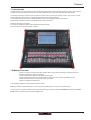
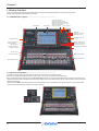
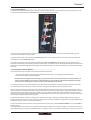
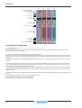
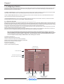
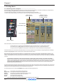
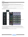
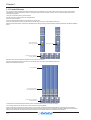
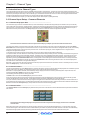
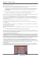
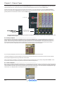
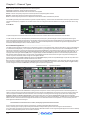
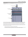
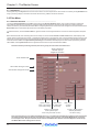
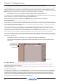
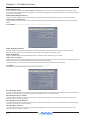
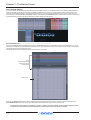
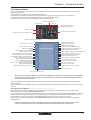
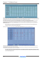
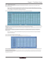
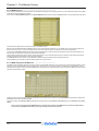
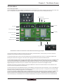
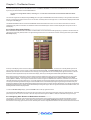
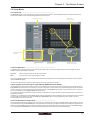
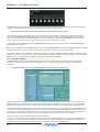
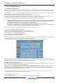
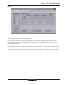
For all output channel types, there is a channel meter displayed in the channel strip. For Input channels, this part of the channel strip
contains the aux outputs, as shown above.
Below the meters section of the output channels, there is an fx output button. This button brings up either the controller display for the
effects preset that has been assigned, or the fx Presets display if no preset has been assigned.
Note that below the aux section of an Input channel, there is a pan control in place of the fx output button. When an
effects preset has been assigned to that channel's Direct Out, touching this pan control brings up the FX preset
controller display.
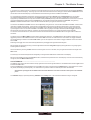
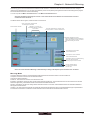
Towards the bottom of the channel strip there is a scribble strip of black and white text boxes displaying the channel names.
Note that the channel naming facility is found in both the channel Setup and Outputs displays.
Below the channel name, there is indication of the lowest group (Grp:) output (along with indication of the lowest direct output (Dir:) in the
case of Input channels), and indication of any control group (CG:) to which the channel belongs.
The on-screen channel has MUTE and HARD indicators located above the scribble strip. Pressing the worksurface MUTE button
silences all outputs from the channel apart from any which have been assigned pre-mute (this option is available for auxes and direct outs)
Pressing the worksurface 2nd Function button to activate the HARD mute silences all outputs from the channel, including those which
are assigned pre-mute.
Immediately below the HARD button, there is a numeric display of the channel’s main fader value in dB.
Below the MUTE button there is a CG MUTE Indicator which shows when the channel is muted as the result of its membership of a
muted Control Group.
At in the bottom left-hand corner of the channel strip, there is a GANG display. To the right of the GANG button there is a SAFE button.
This indicates the Safe status of the channel.
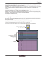
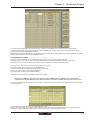
2.3.2 Channel Strip Insert Areas ..................................................
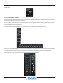
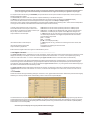
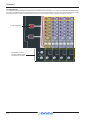
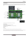
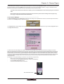
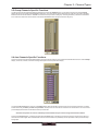
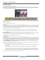
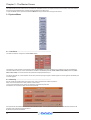
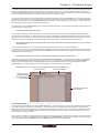
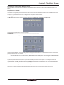
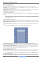
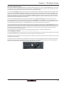
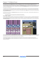
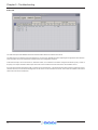
Both channel strip insert areas include a button for switching that insert on and off. The button is grey when the send is off, and red when
it is on.
Note - If the Insert button is off the Insert Send will still be active if routed to an output.
Below the on/off button, there is a display of the current insert routing. The send route is displayed on the left, prefixed by S:, and the
return route is displayed on the right, prefixed by R:. If no routing has been selected, these areas are blank apart from these prefixes. If the
channel is stereo, only the left side of the insert routing is displayed.
2.3.3 Console Output and Insert Routing ...................................
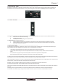
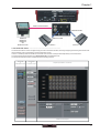
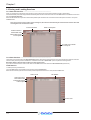
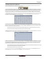
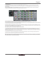
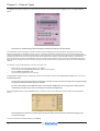
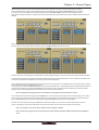
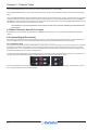
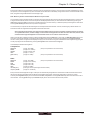
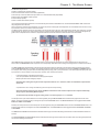
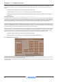
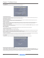
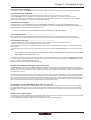
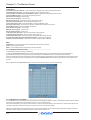
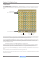
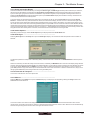
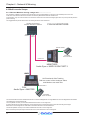
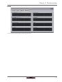
The Output displays for all four channel types allow direct routing either to the external IO racks, or to one of a variety of internal locations,
for both the channel’s main output (or direct output in the case of Input channels), and its insert send and return. Towards the bottom of
the Outputs display, there are three buttons marked output (direct in Input channels), insert A and insert B. Selecting one of these
buttons assigns that send (or send and return) to the signal routing area above it: When either insert is assigned, the ins A send or ins B
send routing button appears in the left-hand column, and the ins A return or ins B return routing button in the right-hand column; When
the output (direct output in Input channels) is assigned, the outputs (direct outs in Input channels) routing button appears in the lefthand column and the right-hand column is left blank. Pressing any of these routing buttons opens a routing display.
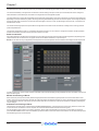
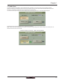
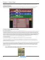
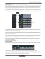
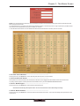
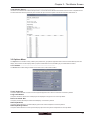
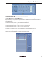
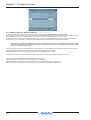
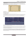
An extra button labelled send+return is included above the ports list in the Insert Send Route display button. When this button is
activated, the send and return routing is linked for all signals within the INTERNAL port: If the Graphic 1 input is assigned to the insert
send, the Graphic 1 output is automatically assigned to that insert return. Similarly, if it is the return which is manually assigned, the send
automatically copies that send assignment. The send+return button is grey when inactive and brown when active.
2.3.4 FX Presets .............................................................................
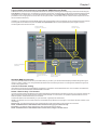
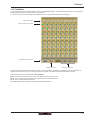
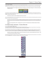
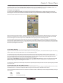
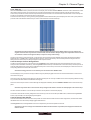
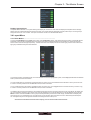
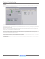
Each channel output or insert send can be sent to an internal FX Unit. Pressing the fx presets button at the bottom of the Outputs
display brings up the fx Presets display. The effects preset is applied to whichever channel output is active in the Outputs display when
the fx presets button is pressed: the main channel output (or direct output), insert send A or insert send B:
1-6