1
Relay Terminal
Module
User’s Manual
(Hardware)
A6TE2-16SRN
Thank you for buying the Mitsubishi general-purpose programmable
controller MELSEC-A Series
Prior to use, please read both this manual and detailed manual
thoroughly and familiarize yourself with the product.
MODEL A6TE2-16SRN-U-E
MODEL
13JL53
CODE
IB (NA)66833-F (1112) MEE
©1997 MITSUBISHI ELECTRIC CORPORATION
z SAFETY PRECAUTIONS z
(Read these precautions before using this product.)
Before using this product, please read this manual and the relevant manuals
carefully and pay full attention to safety to handle the product correctly.
The instructions given in this manual are concerned with this product. For the
safety instructions of the programmable controller system, please read the
CPU module user's manual.
In this manual, the safety precautions are classified into two levels:
"
WARNING" and "
CAUTION".
Under some circumstances, failure to observe the precautions given under
" CAUTION" may lead to serious consequences.
Observe the precautions of both levels because they are important for personal
and system safety.
Make sure that the end users read this manual and then keep the manual in a
safe place for future reference.
[DESIGN PRECAUTIONS]
WARNING
z Install a safety circuit external to the programmable controller that keeps
the entire system safe even when there are problems with the external
power supply or the programmable controller main module.
An accident may occur by a false output or a malfunction.
Output could be left ON or OFF when there is trouble in the output
module's relay or transistor. So build an external monitoring circuit that
will monitor any signal output that could cause serious trouble.
z In an output module, build a safety circuit such as a fuse externally of the
module, because there is a possibility of fire or smoke in the case when
overcurrent exceeding the rating flows continuously for a prolonged time
due to shorted load.
CAUTION
z Do not bunch the control wires or communication cables with the main
circuit or power wires, or install them close to each other. They should
be installed 100mm (3.9 in) or more from each other. Not doing so could
result in noise that would cause malfunction.
[INSTALLATION PRECAUTIONS]
CAUTION
z Use the module in the environment given in the general specifications of CPU
module user's manual.
Using the programmable controller outside the range of the general specifications
may result in electric shock, fire or malfunction, or may damage the product.
z Load a cable by inserting to a module connector until a clicking sound comes.
Check any looseness after the loading. False connection may cause a mis-input
or mis-output.
z Load a module by pressing against the DIN rail until a clicking sound comes.
Check any looseness after the loading. Improper installation may cause the
module to fall out, resulting in breakdowns.
z Do not directly touch the module's conductive parts or electronic components.
Doing so could cause malfunction or trouble in the module.
[WIRING PRECAUTIONS]
WARNING
z Before beginning any installation or wiring work, make sure all phases of the
power supply have been obstructed from the outside.
Failure to completely shut off the power supply phases may cause electric shock
and /or damage to the module.
z When turning on the power or operating the module after installation or wiring
work, be sure the module's terminal covers are correctly attached.
Failure to attach the terminal covers may result in electric shock.
CAUTION
z When wiring the programmable controller, check the rated voltage and terminal
layout of the wiring, and make sure the wiring is done correctly. Connecting a
power supply that differs from the rated voltage or wiring it incorrectly may cause
fire or failure.
z Tighten the terminal screws with the specified torque. If the terminal screws are
loose, it may result in short circuits, fire or malfunction. Tightening the screws too
far may cause damage to the screw and /or the module, resulting in short circuits,
fire or malfunction.
z Be sure there are no foreign substances such as sawdust or wiring debris inside
the module. Such debris could cause fire, failure or malfunction.
z Be sure to fix wires or cables leading from the module by placing them in the duct
or clamping them. Cables not placed in the duct or without clamping may hang or
shirt, allowing them to be accidentally pulled, which may result in a module
malfunction and cable damage.
z Install our programmable controller in a control panel for use. Wire the main power
supply to the power supply module installed in a control panels through a
distribution terminal block.
Furthermore, the wining and replacement of a power supply module have to be
performed by a maintenance worker who acquainted with shook protection. (For
the wiring methods, refer to section 4.1)
[STARTING AND MAINTENANCE PRECAUTIONS]
WARNING
z Do not touch the terminals while the power is on. Doing so may cause electric
shock or malfunction.
z Switch off all phases of the externally supplied power used in the system when
cleaning the module or retightening the terminal or module mounting screws.
Not doing so could result in electric shock.
Undertightening of terminal screws can cause a short circuit or malfunction.
Overtightening of screws can cause damages to the screws and/or the module,
resulting in fallout, short circuits, or malfunction.
[STARTING AND MAINTENANCE PRECAUTIONS]
CAUTION
z Do not disassemble or modify the modules. Doing so could cause failure,
malfunction, injury or fire.
z When detaching the communication cable or power cable from the module, do not
pull the cable portion. For cables with connectors, hold the connector at the
junction to the module, then detach it. For cables without connectors, first loosen
the screw at the junction, then detach the cable.
Pulling the cable portion while it is connected to the module may cause a
malfunction or damage to the module and cable.
z Be sure to shut off all phases of the external power supply used by the system
before connecting or disconnecting the cable.
Failure to do so may result in failure or malfunctions of the module
z Before touching the module, always touch grounded metal, etc. to discharge static
electricity from human body, etc.
Not doing so can cause the module to fail or malfunction.
[DISPOSAL PRECAUTIONS]
WARNING
z When disposing of this product, treat it as industrial waste.
z CONDITIONS OF USE FOR THE PRODUCT z
(1) Mitsubishi programmable controller ("the PRODUCT") shall be used in conditions;
i) where any problem, fault or failure occurring in the PRODUCT, if any, shall not
lead to any major or serious accident; and
ii) where the backup and fail-safe function are systematically or automatically
provided outside of the PRODUCT for the case of any problem, fault or failure
occurring in the PRODUCT.
(2) The PRODUCT has been designed and manufactured for the purpose of being
used in general industries.
MITSUBISHI SHALL HAVE NO RESPONSIBILITY OR LIABILITY (INCLUDING,
BUT NOT LIMITED TO ANY AND ALL RESPONSIBILITY OR LIABILITY BASED
ON CONTRACT, WARRANTY, TORT, PRODUCT LIABILITY) FOR ANY INJURY
OR DEATH TO PERSONS OR LOSS OR DAMAGE TO PROPERTY CAUSED BY
the PRODUCT THAT ARE OPERATED OR USED IN APPLICATION NOT
INTENDED OR EXCLUDED BY INSTRUCTIONS, PRECAUTIONS, OR WARNING
CONTAINED IN MITSUBISHI'S USER, INSTRUCTION AND/OR SAFETY
MANUALS, TECHNICAL BULLETINS AND GUIDELINES FOR the PRODUCT.
("Prohibited Application")
Prohibited Applications include, but not limited to, the use of the PRODUCT in;
y Nuclear Power Plants and any other power plants operated by Power companies,
and/or any other cases in which the public could be affected if any problem or
fault occurs in the PRODUCT.
y Railway companies or Public service purposes, and/or any other cases in which
establishment of a special quality assurance system is required by the
Purchaser or End User.
y Aircraft or Aerospace, Medical applications, Train equipment, transport
equipment such as Elevator and Escalator, Incineration and Fuel devices,
Vehicles, Manned transportation, Equipment for Recreation and Amusement,
and Safety devices, handling of Nuclear or Hazardous Materials or Chemicals,
Mining and Drilling, and/or other applications where there is a significant risk of
injury to the public or property.
Notwithstanding the above, restrictions Mitsubishi may in its sole discretion,
authorize use of the PRODUCT in one or more of the Prohibited Applications,
provided that the usage of the PRODUCT is limited only for the specific
applications agreed to by Mitsubishi and provided further that no special quality
assurance or fail-safe, redundant or other safety features which exceed the general
specifications of the PRODUCTs are required. For details, please contact the
Mitsubishi representative in your region.
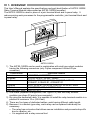
1. OVERVIEW
This User's Manual explains the specifications and part identification of A6TE2-16SRN
Relay Terminal Module (abbreviated as A6TE2-16SRN hereafter).
The A6TE2-16SRN is used in place of a joint terminal block and in-panel relay. It
reduces wiring work processes for the programmable controller, joint terminal block and
in-panel relay.
A6TE2-16SRN
1) The A6TE2-16SRN can be used in combination with sink type output modules
having the following connectors (only Fujitsu component Limited 40-pin
connector).
Classification
Applicable Models
L series
LY41NT1P, LY42NT1P
Q series
QY41H, QY41P, QY42P, QH42P
AnS series
A1SY41, A1SY41P, A1SY42, A1SY42P, A1SH42,
A1SH42P, A1SH42-S1, A1SH42P-S1
A series
AY42, AY42-S1, AY42-S2, AY42-S3, AY42-S4, AH42
CC-Link
AJ65SBTCF1-32T, AJ65BTC1-32T
MELSECNET-MINI AJ35TC1-32T
2) One cable (separate arrangement; see Figure 4.2) and two relay terminal
modules can share 32 points (one connector).
3) By using the dedicated cable, it is possible to install the relay terminal module in a
position of maximum 10 m (32.8 feet).
4) There are five types of dedicated cables, each having different cable length.
5) Because it is a socket-type relay, each relay can be replaced individually as
necessary.
y The relay has a structure that allows secure installation and prevents drop-offs
due to vibration, etc.
y It is supplied with a relay removal tool.
6) Because it can be replaced by a relay output, it can be used either for AC or DC
with larger current capacity.
7) Self-up screws are adopted so that the terminal screws do not fall off.
8) Wiring works have been simplified by the indication on the symbol sheet of the
relay terminal module.
9) Only a DIN rail can be installed.
10) 2-wire load can be connected.
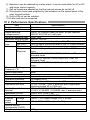
2. Performance Specifications
Item
Number of output
Isolation method
Rated switching
voltage/current
Minimum switching load
Maximum switching load
Response OFF→ON
time
ON→OFF
Life
Mechanical
(*1)
Electrical
Maximum switching
frequency (*2)
Noise suppression
Fuse
Common wiring system
Operation indication
External wiring system
Applicable wire size
Applicable solderless
terminal
Applicable DIN rail
Accessory item
External
Voltage
supply
Current
power
Internal current
consumption (5VDC)
Weight
Specifications
16 points
Relay insulation
24VDC 2A (resistive load) per point, 8A per common
240VAC 2A (COS φ=1) per point
5VDC 1mA
264VAC 125VDC
10ms or below (excluding delay of the PC output module)
12ms or below (excluding delay of the PC output module)
Over 20 million times
Rated switching voltage/current load: Over 100 thousand
times
200VAC 1.5A, 240VAC 1A(COSφ=0.7) Over 100
thousand times
200VAC 1A, 240VAC 0.5A(COSφ=0.35): Over 100
thousand times
24VDC 1A, 100VDC 0.1A(L/Rφ=7ms): Over 100 thousand
times
3,600 times per hour
None
None
8 points 1 common (common terminals: TB19, TB21)
ON display (LED)
38-point terminal block connector (M3 screw)
0.75 to 1.25 mm2, max. 2 wires per point (Applicable
tightening torque 60 to 100N⋅cm)
1.25-3 1.25-MS3 1.25-B3A 1.25-C3A
V1.25-3 V1.25-MS3 V1.25-B3A max. 2 wires per point
TH35-7.5Fe. TH35-7.5AI
Relay removal tool (RV9Z-T01)
24VDC ± 10% ripple voltage, 4VP-P or less
350mA (TYP. 24VDC, all points ON)
0.35kg
Item
Relays for replacement
Remark
Specifications
RV3T-3G24 (made by IDEC Corporation, prepared by user)
24VDC, connector (40-pin, made by FUJITSU
COMPONENT LIMITED)
For a sink tank type output, use 2-wire terminal block.
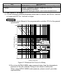
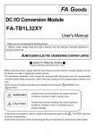
*1: See Figure 2.1 for details.
*2: For the maximum switching frequency when load L is driven, set ON for 1 second
or longer and OFF for 1 second or longer.
REMARK
1) See the User's Manual of the programmable controller CPU for the general
specification.
500
Life (10 thousand times)
100
70
50
40
120VAC COSø=1
24VDC
30VDC T=0ms
240VAC COSø=-1
30
20
120VAC COSø=0.4
100V to 120VDC
T=7 to 40ms
10
220VAC COSø=0.4
240VAC
30VDC
T=40ms
30VDC T=7ms
5
0.05
0.1
0.2 0.3
0.5
1
2
3
5
Contact current (A)
Figure 2.1 Electrical Life Curve of a Relay
2) Do not use A6TE2-16SRN under pressure higher than the atmospheric
pressure of 0m (0ft.) altitude. Doing so can cause a malfunction.
When using A6TE2-16SRN under pressure, please consult your sales
representative.
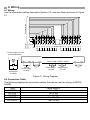
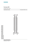
3. Part Identification and External Dimensions
6)
7)
5)
MITSUBISHI
0
1
1
3
2
5
4
POWER
2
7
6
1)
67 (2.6)
4)
3
4
9
8
5
11
13
10
12
6
15
14
7
17
16
8
19
18
21
20
9
23
22
A
25
24
B
27
26
C
29
28
D
31
30
E
33
32
F
35
34
37
36
A)
38
2.5
(0.1)
153 (6)
180 (7.1)
3)
2)
When the terminal cover is open
(24.5)
(1)
52.6 (2.1)
40 (1.6)
(30.1)
(1.2)
7)
MITSUBISHI
DIN rail
8)
(56.3)
(2.2)
When a DIN rail is installed
(Unit:mm(in))
View from A)
1
3
+24V
2
24G
5
7
9
Y0
Y1
Y2
4
6
8
11
Y3
10
13
Y4
12
15
Y5
14
17
Y6
16
19
Y7
18
21
23
20
25
Y8
COM1 COM3
22
24
27
Y9
26
28
31
YB
30
33
YC
32
35
YD
34
37
YE
36
YF
38
COM2 COM2 COM2 COM2 COM2 COM2 COM2 COM2 COM2 COM4 COM4 COM4 COM4 COM4 COM4 COM4 COM4 COM4
7) Rear of the symbol sheet
Number
1)
2)
3)
4)
5)
6)
7)
8)
29
YA
Name
Cover
Terminal block
Terminal cover
Connector
LED (For output confirmation)
Relay removal tool
Symbol sheet
Hook (used for removing DIN rail)
4. Wiring
Terminal
block area
Connector line
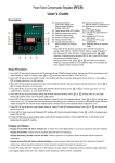
4.1 Wiring
Use the connection cables descried in Section 4.2, and wire them as shown in Figure
4.1.
Y0 Y1 Y2 Y3 Y4 Y5 Y6 Y7 COM1 COM3 Y8 Y9 YA YB YC YD YE YF
+24V
24G
C2 C2 C2 C2 C2 C2 C2 C2 COM2 COM4 C4 C4 C4 C4 C4 C4 C4 C4
*1 Power supply for load
is described below.
or
+
+24V
24G Y0
C2
COM1 COM 2 COM 3 COM 4
C4
YF
+
or
100/200VAC
or 24VDC
Load
24VDC
Power supply
for relay
Load
Power supply
for load
Power supply
for load
Figure 4.1 Wiring Diagram
4.2 Connection Cable
The following displays the connection cables that can be used for wiring of A6TE216SRN.
Type
AC06TE
AC10TE
AC30TE
AC50TE
AC100TE
Cable length L
0.6m (2ft)
1m (3.2ft)
3m (9.8ft)
5m (16.4ft)
10m (32.8ft)
B side: last 16 points
(Y10 to Y1F)
0
35 .8)
(13
L
B
A
AC
TE
3
(13 50
.8)
A side: first 16 points
(Y0 to YF)
Figure 4.2 Connection Cable
(Unit: mm (in))
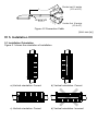
5. Installation
36
F
1
35
E
37
38
5.1 Installation Orientation
Figure 5.1 shows the orientation of installation.
7
34
32
33
30
31
C
B
1
6
28
8
2
29
5
A
9
26
24
9
13
25
4
12
8
POWER
11
23
10
3
27
0
4
MITSUBISHI
3
D
2
22
5
14
21
15
20
6
16
7
7
17
19
6
20
16
18
18
19
17
12
4
3
10
11
9
26
POWER
8
25
24
23
13
5
22
14
15
21
9
A
8
6
7
1
4
32
C
31
5
30
36
E
35
1
2
34
D
33
0
MITSUBISHI
B
29
2
28
3
27
F
37
38
b) Vertical orientation: Correct
0
1
MITSUBISHI
2
3
4
5
6
20
7
22
21
24
23
8
26
25
9
28
27
A
30
29
B
32
31
C
34
33
D
36
35
E
38
37
F
POWER
34
F
19
32
E
35
18
30
D
33
17
28
31
16
26
C
29
15
24
B
27
14
22
A
25
13
20
9
23
12
18
21
11
16
8
19
10
14
7
17
9
12
6
15
8
10
5
13
7
8
4
11
6
6
3
9
5
4
2
7
4
2
1
5
3
0
3
2
POWER
MITSUBISHI
1
1
a) Vertical orientation: Correct
37
36
38
c) Vertical orientation: Correct
d) Vertical orientation: Incorrect
e) Horizontal orientation: Correct
f) Horizontal orientation: Incorrect
Figure 5.1 Installation Orientation (Horizontal view)
Point
Confirm that the relay is securely installed before turning on the power supply for the
first time after shipment.
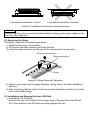
5.2 Replacing the Relay
The relay is replaced in the following manner.
1) Open the top cover of the module.
2) Pull out the red relay removal tool at the left end.
3) Insert the relay removal tool from top of the relay and pull out the relay.
Relay removal direction
Relay removal tool
Relay
Figure 5.2 Relay Removal Procedure
4) Mount a new relay from the upper direction, taking note of the relay installation
direction.
5) After confirming that the relay is firmly connected and there is no bent in its lead,
turn on the power supply.
5.3 Installation and Removal to/from a DIN Rail
1) Installation to a DIN Rail
a) Insert the top of the DIN rail to the upper side of the groove for the DIN rail.
b) Fix the module to the DIN rail by pressing against the rail.
Module
DIN rail
Direction of module installation
Figure 5.3 Installation Procedure to a DIN Rail
2) Removal from a DIN Rail
a) Pull down the hook at the bottom of the module with a flat blade screwdriver.
b) Pull the module forward while the hook is pulled down, then remove the module
from the DIN rail.
Module
DIN rail
Driver
Direction of module removal
Figure 5.4 Removal Procedure from a DIN Rail
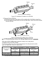
6. Precautionary Items for Relay Replacement
When the A6TE2-16SRN relay is replaced, always use a relay that is
compatible with the A6TE2-16SRN.
The following table shows the relationship between the relay terminal module
types and applicable relays for replacement.
Relay for replacement ({: usable, ×: unusable)
Existing
New type
New type
Relay terminal
replacement
replacement relay
replacement
module
relay
(with an adapter)
relay
RV3T-3G24
RV3T-3G24MA
RV3S-3B24S
{
A6TE2-16SRN
×
×
{
{
A6TE2-16SR *1
×
*1:Conventional relay terminal module
WARRANTY
Mitsubishi will not be held liable for damage caused by factors found not to be the cause of
Mitsubishi; machine damage or lost profits caused by faults in the Mitsubishi products; damage,
secondary damage, accident compensation caused by special factors unpredictable by Mitsubishi;
damages to products other than Mitsubishi products; and to other duties.