1
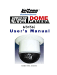
IP Fast Dome Camera
PIH - 7000/7600/7625 IP Series
Installation / Operation Manual
December 18, 2003
CONTENTS
Chapter 1. WARNINGS & CAUTIONS
Chapter 2. INTRODUCTION
Chapter 2-1. What is Merit Li-Lin IP Fast Dome?
Chapter 2-2. Features
Chapter 3. STRUCTURAL ELEMENT
Chapter 4. FAST DOME CAMERA SETUP
Chapter 4-1. DIP Switch Setting
Chapter 4-2. Fast Dome ID Address Setting Refer Chart
Chapter 4-3. Fast Dome Connection Jack and Cable Requirement
Chapter 5. HARDWARE INSTALLATION
Chapter 5-1. Indoor Installation Structural Drawing
Chapter 5-2. Outdoor Installation Structural Drawing
Chapter 5-3. Embedded Mounting (False Ceiling)
Chapter 5-4. Attached Mounting (False Ceiling)
Chapter 5-5. Pendant Mounting (External Housing)
Chapter 6. SOFTWARE INSTALLATION
Chapter 6-1. Assign IP by IP Installer
Chapter 6-2. Assign IP Address by ARP
Chapter 6-3. Verify and Complete the Installation from Your Browser
Chapter 7. SYSTEM CONFIGURATION
Chapter 7-1. Fast Dome and Keyboard
Chapter 7-2. Fast Dome, Matrix and Keyboard
Chapter 7-3. Fast Dome, DVR and Keyboard
Chapter 7-4. Network Installation Procedure
Chapter 8. OPERATION
Chapter 8-1. Initial Power Up Inspection
Chapter 8-2. Manual Operation (Pan/Tilt Control)
Chapter 8-2-1. Fast Dome Selection
Chapter 8-2-2. Zoom Lens Control
Chapter 8-2-3. Focus Control
Chapter 8-2-4. Iris Control
Chapter 8-2-5. Horizontal 180 Instant Flip
Chapter 8-3. Preset Positions Setting
Chapter 8-4. Recalling Preset Positions
Chapter 8-5. Setting Preset Group
Chapter 8-6. Changing Preset Data
Chapter 8-7. Activating Auto Pan
Chapter 8-8. Deleting Preset Data
Chapter 8-9. Alarm Management
Chapter 8-9-1. Alarm Response Mode
Chapter 8-9-2. Alarm Output
Pages
1
2
2
3
5
6
6
7
8
10
10
11
12
15
17
22
22
25
27
28
28
30
31
32
33
33
33
34
34
34
35
35
36
38
38
39
39
40
40
40
41
Pages
Chapter 9.
HOW TO USE IP FAST DOME HOME PAGE
42
Chapter 9-1.
Browsing Video Home Page
42
Chapter 9-2.
IP Fast Dome Configuration Page
43
Chapter 9-3.
Server Configurations
44
Chapter 9-4.
User Settings
45
Chapter 9-5.
Clock Settings
47
Chapter 9-6.
System Commands
47
Chapter 9-7.
Network
48
Chapter 9-8.
SMTP Settings
49
Chapter 9-9.
DHCP Settings
49
Chapter 9-10.
DDNS Settings
50
Chapter 9-11.
GPIO Stats
52
Chapter 9-12.
PTZ Adjustment
52
Chapter 9-13.
Video Setup
53
Chapter 9-14.
Video Adjustment
53
Chapter 9-15.
Event Management
54
Chapter 9-16.
Event Edit
55
Chapter 10. SPECIFICATION
57
Appendix A.
Upgrading the Software
61
Appendix B.
Update custom web pages
64
Appendix C.
Emergency Factory Default
66
Appendix D.
Trouble Shooting
67
Chapter 1.
WARNINGS & CAUTIONS
Please read the manual before attempting installation or operation
1. Please be aware to the warnings and cautions notice.
2. Don't use any chemical detergent to clean the machine surface, use a damp cotton cloth
only. Regularly clean the dome cover to assure proper focus ability.
3. Please install the Fast Dome in a dry area, water and high humidity may cause damage on
internal parts. External housing should be used for outdoor installation.
4. Please use parts supplied by the manufacturer only, any unqualified part using in the
equipment may violate the warranty.
5. Avoid installing the equipment in an unstable area. Make sure the area is firm and stable.
Falling equipment may injure personnel and damage the equipment.
6. Do not install the equipment near any flammable gas. Violation may cause fire or injury.
7. Avoid running video cable and signal cable through or passing interference sources such
as video waves, broadcast station, power generator, elevator motor or high voltage area
..... etc. Violation may cause interference.
8. Make sure the power cable is properly fixed. Un-suitably fixed cable may cause serious
short circuit or fire.
9. Correct cable connection is important. Do not place any object on the connection cable
and change the cable if there is damage on cable. Violation may cause short circuit, fire
and injury.
10. Make sure ground is well connected to avoid damage caused by lightning.
11. Do not put any foreign objects inside the equipment and do not spray any liquid on
equipment. This will avoid short circuit damage.
12. Do not touch power connection with wet hands to avoid short circuit or electricity shock.
13. Do not apply smash-force on the equipment. Violation may cause damage.
14. Do not install the equipment in a location that may expose the equipment directly to
sunlight. Violation may cause colour fading or damage.
15. Do not install the equipment in high temperature or low temperature environment to
avoid damage. The normal operational temperature is between -5 C ~ +50 C.
16. Fast Dome contains high sensitive electric parts inside. Do not try to repair them without
qualified personnel.
17. Turn off the power immediately and contact the technician when the following occurs:
A. Damage on power cable or plug.
B. Water leak into the equipment.
C. Fast Dome can not be operated normally.
D. Equipment falling on ground or damage on external case.
E. Unusual occurrence.
18. Warning: Do not try to repair the equipment. Only a qualified technician may disassemble
and repair the equipment. Shut off the power before disassemble the equipment and don't
put power on unless the case is completely assembled.
Chapter 1.
1
Chapter 2.
INTRODUCTION
Chapter 2-1. What is Merit Li Lin IP Fast Dome?
Merit Li Lin's IP Fast Dome is an integrated Internet-Based fast dome device with a built-in
Web server running TCP/IP to distribute the compressed live video into Intranet/Internet
through the Ethernet connection.
Merit Li Lin PIH-7000/7600/7625 series IP Fast Dome :
You can easily manipulate and configure the fast dome with the Web-base control over the
Internet via the standard browser such as Explorer
TM
TM
and Netscape .
The IP Fast Dome contains an image compression chipset, capable of delivering standard
JPEG, MJPEG, and real-time video, to distribute monitored images into the limited network
bandwidth.
Measure only 145mm (5.6") in diameter and is capable of making 360 degrees continuous
rotation with a speed range of 0.18 to 360 degrees per second, ensures direct and accurate
target positioning. When required the dome can be quickly spun through 180 degrees, an
important feature when something passes directly under the camera.
Up to 128 preset positions can be programmed and recalled with an accuracy of 0.25 degrees.
First 16 presets can be divided into 4 groups for auto touring with individual setting for
speed and dwell time.
Each IP Fast Dome has 6 alarm inputs (expandable to 64) can drive the dome to any position
in under second. A local alarm output can be configured as NO or NC and two types of alarm
response mode provide flexible alarm management.
Chapter 2.
2
Chapter 2-2. Features
17X Auto Focus Lens (PIH-7000 IP)
Build-in 17X optical zoom lens with focal length 3.9 ~ 66.3mm
22X Auto Focus Lens (PIH-7600 IP)
Build-in 22X optical zoom lens with focal length 3.9 ~ 85.4mm
25X Auto Focus Lens (PIH-7625 IP)
Build-in 25X optical zoom lens with focal length 3.8 ~ 95.0mm
Automatic / Manual Iris Control
360 continuous rotation
Up to 128 programmable preset positions
Preset positions auto scanning
Highspeed rotation and tilt, speed range varies from 0.18 /sec ~ 360 /sec
180 Horizontal Instant Flip
6 alarm inputs, 1 alarm output can be set as NO (normally open) or NC (normally close) for
each Fast Dome
Two types of alarm response mode: Lock Mode, Release Mode
Build in 1/4" CCD high resolution DSP colour camera:
* 17X & 22X optical lens models:
1. 480 TV Lines high resolution
2. 0.8 Lux high sensitivity
3. White Balance Control
(Auto White Balance and Manual White Balance(Indoor/Outdoor))
4. Back Light Compensation (ON/OFF)
5. Auto Gain Control (ON/OFF)
* 25X optical lens model:
1. Color / Mono Switch (IR Cut Filter)
ON
OFF
AUTO
Color
Mono
Switch from color to mono when light drops below 3 lux.
2. 480 TV Lines (Color) ; 570 TV Lines (Mono)
3. 0.1Lux (Color) ; 0.01Lux (Mono)
4. On-Screen Setup Menu , 21 high sens setting items.
5. White Balance Control : Auto Correction , Auto Tracking , Fix (Indoor/Outdoor)
6. Back Light Compensation (On/Off)
Chapter 2.
3
7. Back Light Compensation Zone (Top , Bottom , Left , Right)
8. Auto Gam Control : 8dB (low) , 22dB (medium) , 36dB (hgih)
9. 8 levels Brightness Adjustment
10. 16 levels Content Adjustment
11. Aperture Correction Adjustment
12. Flickerless : On/Off
13. Sensitivity Enhancement : On/Off
RS-485 control interface
Up to 64 Fast Dome configuration
Compatible with PC control (protocol required)
12Vdc voltage input (power supply options: 90 ~ 260Vac or 24Vac)
Flexible Mounting: Indoor - embedded and attached types, Outdoor - with weather resistant
housing
Integrated fast dome with web enable providing Internet capability.
IP assignment via ARP/Web Page/IP Installer easy to install for users.
JAVA-based web page providing maximum platform compatibility.
Active-X control for Internet Explorer
TM
providing maximum performance.
Motion Detection / Date / Time / GPIO Input for event trigger.
Email / FTP / Internal Buffer Storage / Relay Out / PPP Dialing Out for event action.
Programmable event script for various application.
LILIN DDNS support for dynamic IP application.
3 - layer User Security Control.
Remote upgradeable firm ware and user content pages via FTP.
Server operating control through CGI base script easy to integrate the application for users.
Green power, fan needless, and hardware watchdog providing robustness system in critical
environment.
Standard BNC connectors, automatic video standard (NTSC/PAL) detection.
Chapter 2.
4
Chapter 3.
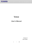
Chapter 3.
STRUCTURAL ELEMENT
Dome Cover
RS-485 In / Out Jack
Camera Case
Alarm In / Out Jack
Decoration Ring
Video In / Out Jack
RJ-45 Jack
Power In Jack
Power/Network LED
Camera Base
5
Chapter 4.
FAST DOME CAMERA SETUP
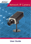
Chapter 4-1. DIP Switch Setting
Camera ID Switch
Fan Power Switch
Camera Function Switch
Alarm Mode Switch
Chapter 4-1-1. Fan Power Switch
Turn the number 2 switch to ON position to activate the internal fan. This will maintain the
temperature inside and make the electric parts longer life.
Chapter 4-1-2. Alarm Mode Switch
Alarm Mode can be set as Lock or Release mode. Turn number 1 switch to ON position to
choose Release mode. Turn number 1 switch to OFF position to choose Lock mode.
Fast Dome has 6 alarm inputs and 1 output, which can be set either NC (normally close) or
NO (normally open) mode. Turn number 2 switch to ON position to choose NC mode.
Turn number 2 switch to OFF position to choose NO mode.
Chapter 4-1-3. Camera Function Switch
17X & 22X optical lens models:
Turn number 1 switch to ON position for AGC function
Turn number 2 switch to ON position for BLC function
Turn number 3 switch to ON position for AWB function
Turn number 3 switch to OFF position for Manual White Balance (MWB)
When fast dome is set to MWB, turn number 4 switch to ON for Outdoor
(color temp. 3200K) or to OFF for Indoor (color temp. 6300K)
Chapter 4.
6
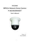
Chapter 4-2. Fast Dome ID Address Setting Refer Chart
Up to 64 Fast Dome Camera can be serial linked in one system.
Therefore each dome is addressing by ID switch located at the base of the Fast Dome.
Below is the address setting for camera 1~64:
1
2
3
4
5
6
7
8
9
10
11
12
13
14
15
16
Chapter 4.
ON
1 2 3 4 5 6 7 8
ON
1 2 3 4 5 6 7 8
ON
1 2 3 4 5 6 7 8
ON
1 2 3 4 5 6 7 8
ON
1 2 3 4 5 6 7 8
ON
1 2 3 4 5 6 7 8
ON
1 2 3 4 5 6 7 8
ON
1 2 3 4 5 6 7 8
ON
1 2 3 4 5 6 7 8
ON
1 2 3 4 5 6 7 8
ON
1 2 3 4 5 6 7 8
ON
1 2 3 4 5 6 7 8
ON
1 2 3 4 5 6 7 8
ON
1 2 3 4 5 6 7 8
ON
1 2 3 4 5 6 7 8
ON
1 2 3 4 5 6 7 8
17
18
19
20
21
22
23
24
25
26
27
28
29
30
31
32
ON
33
1 2 3 4 5 6 7 8
ON
34
1 2 3 4 5 6 7 8
ON
35
1 2 3 4 5 6 7 8
ON
36
1 2 3 4 5 6 7 8
ON
37
1 2 3 4 5 6 7 8
ON
38
1 2 3 4 5 6 7 8
ON
39
1 2 3 4 5 6 7 8
ON
40
1 2 3 4 5 6 7 8
ON
41
1 2 3 4 5 6 7 8
ON
42
1 2 3 4 5 6 7 8
ON
43
1 2 3 4 5 6 7 8
ON
44
1 2 3 4 5 6 7 8
ON
45
1 2 3 4 5 6 7 8
ON
46
1 2 3 4 5 6 7 8
ON
47
1 2 3 4 5 6 7 8
ON
48
1 2 3 4 5 6 7 8
7
ON
1 2 3 4 5 6 7 8
ON
1 2 3 4 5 6 7 8
ON
1 2 3 4 5 6 7 8
ON
1 2 3 4 5 6 7 8
ON
1 2 3 4 5 6 7 8
ON
1 2 3 4 5 6 7 8
ON
1 2 3 4 5 6 7 8
ON
1 2 3 4 5 6 7 8
ON
1 2 3 4 5 6 7 8
ON
1 2 3 4 5 6 7 8
ON
1 2 3 4 5 6 7 8
ON
1 2 3 4 5 6 7 8
ON
1 2 3 4 5 6 7 8
ON
1 2 3 4 5 6 7 8
ON
1 2 3 4 5 6 7 8
ON
1 2 3 4 5 6 7 8
49
50
51
52
53
54
55
56
57
58
59
60
61
62
63
64
ON
1 2 3 4 5 6 7 8
ON
1 2 3 4 5 6 7 8
ON
1 2 3 4 5 6 7 8
ON
1 2 3 4 5 6 7 8
ON
1 2 3 4 5 6 7 8
ON
1 2 3 4 5 6 7 8
ON
1 2 3 4 5 6 7 8
ON
1 2 3 4 5 6 7 8
ON
1 2 3 4 5 6 7 8
ON
1 2 3 4 5 6 7 8
ON
1 2 3 4 5 6 7 8
ON
1 2 3 4 5 6 7 8
ON
1 2 3 4 5 6 7 8
ON
1 2 3 4 5 6 7 8
ON
1 2 3 4 5 6 7 8
ON
1 2 3 4 5 6 7 8
Chapter 4-3. Fast Dome Connection Jack and Cable Requirement
(Alarm Input)
(Alarm Output)
1. Power In Jack
DC12V Input Voltage, Power Consumption 1.2Adc, Center Pin 2.0mm.
Require Cable : 18 AWG x 2C
2. Video out BNC Jack
Video Signal Output CVBS 1.0Vpp 75
BNC.
Recommend Data Cable : 5C2V
3. Alarm In / Out Jack
Each fast dome contains 6 alarm inputs and 1 alarm output.
Alarm Input Voltage 5.6Vmax, Output 0.5A 120Vac / 1A 24Vac.
Recommend Data Cable : UL 26 AWG 80
300V
UL 24 AWG 80
300V
4. RS-485 In / Out Jack
RS-485 Input (TXDI+, TXDI-) to receiver signal from keyboard, matrix, DVR or multiplexer
through twisted pair cable.
RS-485 Output (TXDO+ , TXDO-) sending out signal to next fast dome through twisted pair
cable.
Recommend Data Cable : 2547 VW-ISC UL 24 AWG x 2C
Transmission Distance : Max. 1 Kilometer
When 24VAC PSU is used, the recommend cables are :
UL SPT-1 VW-1 18AWG x 2C
UL SPT-2 105 VW-1 18AWG x 3C
The distance between 24Vac PSU and fast dome can not exceed 200meters.
8
Chapter 4.
5. Power / Network LED
Power / Status LED
Power on : constant red.
Emergency factory default (refer to Appendix C Emergency Factory Default) :
Blinking orange (i.e. Red mixed with green).
Network LED
Network Link (connected) : Constant red.
Network have activities : Blink red.
Data sent out from server : Blink green.
Network disconnected : Constant slow blinking green.
Upgrading software (refer to Appendix A Upgrading the software) : Constant slow to fast
blinking of orange.
6. Ethernet Jack
Ethernet cable (twisted pair CAT5 terminated cable with a standard RJ-45 connector) to IP
Fast Dome and attach it to the network.
Standard IEEE802.3 10 Base T port.
Chapter 4.
9
Chapter 5.
HARDWARE INSTALLATION
Chapter 5-1. Indoor Installation Structural Drawing
Embedded Mounting
Chapter 5.
Attached Mounting
10
Chapter 5-2. Outdoor Installation Structural Drawing (Pendant Mounting)
Chapter 5.
11
Chapter 5-3. Embedded Mounting (False Ceiling)
Step 1
Ceiling Preparation
l Drill a 3/32" (2.4mm) hole at the center of
the chosen area.
Step 2
The Ceiling Ring
l Attach the ring to ceiling
Step 3
l Use a pencil and a compasses to mark a
circle 6.7" (170mm) in diameter and cut
the circle.
l Tighten the three tapping
screws into the ceiling or
three machine screws with
three screw nuts
The Fix Ring
l Turn the dome cover
anti-clockwise
l Put on the three L
shape screw nuts
Chapter 5.
l Ring size and screw
location
l Separate the dome
cover from camera
l Attach fix ring
with screw nuts
12
l Tighten the three
black screws into
the screw nuts
Step 4
Camera Setting
l Untighten the three l Turn the camera
l Separate the camera l Unplug the
connection cable
screws from the base
body anti-clockwise
body and base
Setting Fast Dome ID
Setting Alarm Mode
Setting Camera Function (17X & 22X optical lens models only)
Setting Fan Power
Refer to page 6,7 for the setting
Step 5
Attach the Camera Body and Base
l Reconnect the
connection cable
Step 6
l Turn camera body
clockwise to tight
position
l Tighten the three
screws to fix the
camera body
l Connect video
signal cable
l Connect alarm
output cable
l Connect Ethernet
cable
Connection
l Connect RS-485
cable
Chapter 5.
l Attach camera
body to base
13
Step 7
Install Camera Body and Decoration Ring
l Put camera body and
the fix ring into the hole
l Turn the camera body
clockwise to tight position
l Put on decoration
ring
Step 8
l Tighten three
black screws
l Turn the ring clockwise
to tight position
Install The Dome Cover
l Attach dome cover
to camera body
l Turn the dome cover
clockwise to tight position
Note : After dome cover is attached, use glass-cleaning cloth to clean dome cover.
Unclean dome cover may affect camera performance.
Chapter 5.
14
Chapter 5-4. Attached Mounting (False Ceiling)
Step 1
Fix The Base
l Turn the dome cover
anti-clockwise
l Separate the dome
cover from camera
l Untighten the three
screws from base
l Turn the camera cover
anti-clockwise
l Separate the camera
body to the base
l Unplug the
connection cable
l Attach base to ceiling
l Tighten the three
tapping screws into
the ceiling
l Base size and
screw location
Step 2
Camera Setting
Setting Fast Dome ID
Setting Alarm Mode
Setting Camera Function (17X & 22X optical lens models only)
Setting Fan Power
Refer to page 6,7 for the setting
Chapter 5.
15
Step 3
Attach Camera Body and Base
l Reconnect the
connection cable
Step 4
l Connect video
signal cable
l Connect alarm
output cable
l Tighten the three screws
Install Dome Cover
l Put on dome cover
to camera body
Chapter 5.
l Connect Ethernet
cable
Install Decoration Ring
l Put on decoration ring to base
Step 6
l Turn camera body
clockwise to tight
position
Connection
l Connect RS-485
cable
Step 5
l Attach camera body
to base
l Turn dome cover clockwise
to tight position
Note : After dome cover is attached, use glass-cleaning cloth to clean dome cover.
Unclean dome cover may affect camera performance.
16
Chapter 5-5. Pendant Mounting (External Housing)
Step 1
Separate PSU and Bracket
l Untighten and pull out
the bolt from the hinge
l Untighten the screws
from PSU box
Step 2
l Separate the housing
and PSU box
Install Power Supply Unit
1.1 When use 24Vac power source:
l Tighten 2 screws to
fix the PSU
l Put the PSU into the
box
1.2 When use 90 ~ 260Vac power source:
l Put PSU into the box
Step 3
l Put the clamp on PSU
Install the Power Box
l Drill 4 holes on
desired locations
Chapter 5.
l Tighten 2 screws to
fix the PSU
17
l Tighten 4 screws to fix
the power box. (These
four screws are not
supplied. User must
prepare their own
screws.)
Step 4
Connection
RS-485
Alarm In Alarm Output
GND
NO
NC
COM
6
5
4
3
2
1
GND
TXDOTXDO+
TXDITXDI+
RJ-45
DC12V Input
VideoOutput
Fan&Heater
Wiring
FastDomeWiring
ACOutput
ACInput
4.1 Connect AC / DC cables:
Untighten the left
knob, put the AC
power cable through
the hole and tighten
the knob
Connect the AC
power cable to AC
Input jack
Connect the AC
power cable(below)
to AC Output jack
Connect the DC
power cable(above)
to DC Input jack
4.2 Connect Alarm, telemetry control (RS-485) and Video cables:
TXDI
TXDI
ALARM 1
GND
Untighten the right knob, put
the Alarm, RS-485, RJ-45
and video cables through the
hole and tighten the knob
Chapter 5.
Connect the telemetry
control (RS-485) to RS-485
Input (TXDI+,TXDI-)
18
Connect the Alarm
input cable to Alarm
Input.
(Alarm 1 & GND)
Connect the network
cable to RJ-45 jack
Step 5
Connect the video
cable to output jack
Attach the base to housing
l Turn the dome cover
anti-clockwise
l Separate the dome
cover from camera
l Untighten the 3
screws from base
l Turn the camera body
anti-clockwise
l Separate the camera
body and base
l Unplug the
connection cable
l Attach the base to
housing
l Connect the housing
cable
l Tighten 3 screws
to fix base
Chapter 5.
19
Step 6
Camera Setting
Setting Fast Dome ID
Setting Alarm Mode
Setting Camera Function (17X & 22X optical lens models only)
Setting Fan Power
Refer to page 6,7 for the setting
Step 7
Attach Camera Body and Base
l Reconnect the
connection cable
Step 8
l Attach camera
body to base
l Turn camera body
clockwise to high
position
l Tighten the three
screws to fix the
camera body
Install The Dome Cover and Housing Cover
l Attach the cover to housing
l Tighten the 3 screws to fix the cover
Note : When Fast Dome is installed inside outdoor housing, please don't attach dome
cover. Violation may affect camera performance.
Step 9
Attach PSU and Bracket
l Attach the housing
back to PSU box
Chapter 5.
l Insert the bolt into
the hinge and tighten
20
Step 10 Connection
l Connect the fan & heater
cable to pin jack
l Connect the Fast Dome
cable to connection jack
Step 11 Install The Power Box, Bracket and Housing
Pendant
l Attach the bracket
and housing to the
box
l Tighten the 4 screws
to fix the bracket
Wall Mounting
l Attach the bracket
and housing to the
box
Chapter 5.
l Tighten the 4 screws
to fix the bracket
21
Chapter 6.
SOFTWARE INSTALLATION
Chapter 6-1. Assign IP by IP Installer
Merit Li Lin IP Installer is a Windows 98/ME/NT/2000 program. It is the software providing
an easier way for the setting of IP address and network configurations of Merit Li Lin's IP Fast
Dome. Using this tool, you can easily set multiple IP Fast Domes at the same time with the
batch setting function. By utilizing IP Installer, the setting process is largely simplified and the
setting time is effectively shortened. Moreover, IP installer can not only save all the
configurations of IP Fast Dome as backup, but also restore the previous configurations of IP
Fast Dome.
* Execute IP Installer
Double click the mouse left button on the IP Installer icon.
The Merit Li Lin IP Installer form is displayed on the screen.
Click this button to search the
IP Fast Dome / Video Server in the LAN.
List all the IP Fast Dome / Video Server
found in the LAN.
Chapter 6.
22
* Preparation before IP Assignment
Always consult your network administrator before assigning the IP address to your IP Fast
Dome / Video Server.
Make sure that the IP Fast Dome is powered on and correctly connected to the network.
Obtain the IP address not used yet from your network administrator.
MAC address : Each IP Fast Dome has a unique Ethernet address (MAC address) shown on
the top of the IP Fast Dome base as the serial number (S/N), 12 digits, e.g. 000429-XXXXXX.
TEST OK
M/N:
POF0312
S/N:
00429-011BF0
Note : You have to separate base from body to see the MAC address. For instruction, please
refer to Chapter 5-3 step 4 to separate the base.
* Assign the IP Address to IP Fast Dome
Select the MAC address of your IP Fast Dome in the list. The MAC address is identical to the
unit's S/N. Click the menu bar View/Property to open the Property Page for the selected item.
After filling in the properties, chick the OK button to submit the settings for the unit and the
settings are activated immediately.
Chapter 6.
23
* Verify the IP Address and Open the Home Page
To access the Home Page of the selected unit, run the View/Open Web on the menu bar. If
your browser is opened and automatically connected to the IP Fast Dome Home Page, it
menas you have assigned an IP Address to the unit successfully. Now you can close the IP
Installer and start to use your IP Fast Dome.
Chapter 6.
24
Chapter 6-2. Assign IP Address by ARP
Before using IP Fast Dome, users must set the IP address in advance. There are two different
ways to set IP address into IP Fast Dome.
Note before IP assignment
Make sure the IP Fast Dome is powered on and connected to the network correctly.
Obtain a unique IP address from your network administrator.
Each IP Fast Dome has a unique Ethernet address (MAC address), which is recorded
as 12 digits serial number labeled at the bottom side of IP Fast Dome / Video Server /
Network Camera, e.g. 000429XXXXXX.
The following example uses the PC with the IP address 192.168.0.1 and is going to setup
IP Fast Dome with the IP address 192.168.0.200 whose MAC address is 000429000150.
Do not use those addresses featured as examples in this document, always consult
your network administrator before assigning an IP address.
The IP address assigned to the IP Fast Dome shall be the same IP domain (presented as
same subnet mask) as the PC IP address. In our case, a PC IP address is 192.168.0.1
and the IP Fast Dome is 192.168.0.200, so the subnet mask shall be 255.255.255.0.
If a PC subnet mask is 255.255.255.128 or higher, then the domain can't cover
192.168.0.200, so the setting won't take effective.
For speedily installing and easily setting the IP Address, there are provides an IP
Installer Wizard for you. Please install the application and see the user's manual for
detailed description and usage.
Step 1
In Windows, open DOS window.
Enter DOS by <Start
Step 2
Program
MS-DOS Prompt>
Ensure the IP address assigned to IP Fast Dome doesn't occupy by other Host.
In DOS window, entering <ping 192.168.0.200> shall get time out message.
C:\> ping 192.168.0.200
Pinging 192.168.0.200 with 32 bytes of data:
Request time out.
Request time out.
Request time out.
Request time out.
Ping statistics for 192.168.0.200:
Packets : Sent = 4, Received = 0, Lost = 4 (100% loss)
Approximate round trip times in milliseconds:
Minimum = 0ms, Maximum = 0ms, Average = 0ms
C:\>
Chapter 6.
25
Step 3
Enter command <arp-s [IP Fast Dome IP Address] [IP Fast Dome MAC Address]>.
In DOS, enter arp-s 192.168.0.200 00-04-29-00-01-50.
Step 4
Enter command <ping-t [IP Fast Dome IP Address]> shall get constant reply after
3~4 timeouts, then prress CTRL-C to exit pinging.
In DOS, enter ping-t 192.168.0.200
C:\> arp-s 192.168.0.200 00-04-29-00-01-50
C:\> ping-t 192.168.0.200
Pinging 192.168.0.200 with 32 bytes of data:
Request time out.
Request time out.
Request time out.
Reply from 192.168.0.200: bytes = 32 time = 5ms TTL = 255
Reply from 192.168.0.200: bytes = 32 time = 4ms TTL = 255
Reply from 192.168.0.200: bytes = 32 time = 4ms TTL = 255
Reply from 192.168.0.200: bytes = 32 time = 4ms TTL = 255
Ping statistics for 192.168.0.200:
Packets: Sent = 7, Received = 4, Lost = 3 (42% loss),
Approximate round trip times in milliseconds:
Minimum = 4ms, Maximum = 5ms, Average = 2ms
Control-C
C:\>
Step 5
Complete setting and verify the installation. Then, open your web browser
(e.g. Internet Explore) and enter the IP address in the Location/Address field.
Consequently, the IP Fast Dome CS video home page will be opened.
Enter http://192.168.0.200 in Location/Address field of Internet Explore, then the
Internet live video can be opened.
Chapter 6.
26
Chapter 6-3. Verify and Complete the Installation from Your Browser
Start your browser and enter the IP Address of your IP Fast Dome in the location/address field.
The IP Fast Dome Camera can support Microsoft Internet Explorer and Netscape. But the voice
feature (Video Server / Network Camera only) can only be run under Microsoft Internet Explorer.
When browsing the Home Page at the first time with the Microsoft Internet Explorer, you must
temporarily lower your security settings to perform a one-time-only installation of ActiveX
component into your workstation, as described below.
From the Tools menu, select Internet Options.
Click the Security tab and make note of your current security settings.
Set the security level to Low and click OK.
Type the Internet Address or Host Name for your IP Fast Dome into the Address field.
A dialog asking if you want to install wcp10.cab will appear. Click yes to start the
installation.
Once the ActiveX installation is complete, return the security settings to their original
value, as noted above.
To continue the configuration of your own application, click the configure button in the top
left corner of this window.
Chapter 6.
27
Chapter 7.
SYSTEM CONFIGURATION
Merit Li Lin's integrated Fast Dome Surveillance System is suitable for a wide range of
surveillance applications. The system cam be as single fast dome with one keyboard or
encompassing as 64 domes with comprehensive matrix switching, PC control and even Digital
Video Recording. Such flexibility means future expansion is easily facilitated.
Chapter 7-1. Fast Dome and Keyboard
Single dome configuration: One Fast Dome Camera connects to one PIH-800II or PIH-801.
Telemetry control is sent via twisted pair between Dome and Keyboard.
Video signal from the dome is sent to monitor or multiplexer or quad or switcher.
RS-485 Connection
1st pin TXDI+ of RS-485 jack at back of the keyboard connects to TXDI+ of RS-485 jack on
fast dome.
2nd pin TXDI- of RS-485 jack at back of the keyboard connects to TXDI- of RS-485 jack on
fast dome.
Chapter 7.
28
Multiple Domes means that more than one fast dome is linked in the system. Each dome
connects to next dome forming a serial linking. Each dome has an individual ID dip switch,
which allows the keyboard to identify each fast dome and make command. Sometimes it is
more convenient to wire a telemetry system in star configuration rather than daisy chain. To
do this a PIH-804 data distributor is necessary. It takes an output from a keyboard or a matrix
and splits the single data line into 4 separate data lines. One keyboard can control up to 64
camera.
RS-485 Connection Between PIH-804 Data Distributor and Fast Dome
1st output TXDI1+ of PIH-804 connects to TXDI+ of 1st fast dome and TXDI1- of PIH-804
to TXDI-of fast dome.
Linking 2nd Fast Dome
TXDO+ of 1st fast dome connects to TXDI+ of 2nd dome and TXDO- of 1st dome to TXDIof 2nd dome.
RS-485 Connection Between PIH-804 Data Distributor and Keyboard
1st pin TXDI+ on RS-485 IN jack of keyboard connects to TXDO+ on RS-485 OUT jack of
PIH-804
2nd pin TXDI- on RS-485 IN jack of keyboard connects to TXDO- on RS-485 OUT jack of
PIH-804
Chapter 7.
29
Chapter 7-2. Fast Dome, Matrix and Keyboard
TXDI+
TXDITXDO+
TXDOGND
Matrix System is designed to process multiple video systems and video switching.
Its central process unit (CPU) can manage multiple video signals simultaneously and control
other linking system, such as PIH-7000/7600/7625 fast dome or PIH-820 telemetry receiver.
All telemetry remote control and signal transmissions are through twisted pair. One matrix can
manage up to 64 fast domes.
Multiple keyboards can be used for matrix control. 1st keyboard is the master and rests are slaves.
Up to 8 keyboards can be used in one system. Each keyboard has a Dip Switch for ID setting.
(Please refer to keyboard's manual for detail)
Fast Domes
RS-485
Pan/Tilt
Cameras
RS-485
FAST
DOME
PIH-820
Receiver
CAMERA
AC
MATRIX
PIH-820
Receiver
PAN/TITL
3
2
TXDI+
TXDI-
PIH-820
Receiver
1
3
2
IN
OUT
TXDO+
TXDO-
1
DC 12V
RS-485
MATRIX
PIH-864
KEYPRO
KEYPRO
RS-485 Connection Between Matrix and Fast Dome
TXD+ of receiver jack on matrix connects to TXDI+ of 1st fast dome and TXD- of matrix to
TXDI- of fast dome.
Linking 2nd Fast Dome
TXDO+ of 1st dome connects to TXDI+ of 2nd dome and TXDO- of 1st dome to TXDI- of
2nd dome. 64 fast dome can be linked through the connection as shown.
RS-485 Connection Between Keyboards
TXDO+ of 1st keyboard RS-485 OUT connects to TXDI+ of 2nd keyboard RS-485 IN.
TXDO- of 1st keyboard RS-485 OUT connects to TXDI- of 2nd keyboard RS-485 IN.
RS-485 Connection Between Keyboard and Matrix
TXDI+ of 1st keyboard RS-485 IN connects to 1st pin TXD+ of matrix's keyboard jack.
TXDI- of 1st keyboard RS-485 IN connects to 2nd pin TXD- of matrix's keyboard jack.
Chapter 7.
30
Chapter 7-3. Fast Dome, DVR Multiplexer Video Managerment System and Keyboard
The DVR System is an advanced digital recording product, with long recording time and easy
searching features. Telemetry remote control is twisted pair for data transmission to the fast
dome. Fast Dome can be controlled directly from the control panel of the DVR, or from
keyboard.
Each DVR video management system can manage 16 video signals (fast domes). Through
RS-485 connection, 16LILIN stand along DVRs can be linked in one system.
RS-485 Connection Between Fast Dome and DVR
TXD+ of DVR RS-485 jack connects to TXDI+ of 1st fast dome and TXD- of DVR to TXDIof fast dome.
Linking 2nd FastDome
TXDO+ of 1st dome RS-485 jack connects to TXDI+ of 2nd dome to TXDO- of 1st dome to
TXDI- of 2nd dome.
RS-485 Connection Between DVRs
TXD+ of 1st DVR pass out RS-485 jack connects to TXD+ of 2nd DVR's keyboard jack.
TXD- of 1st DVR pass out RS-485 jack connects to TXD- of 2nd DVR's keyboard jack.
RS-485 Connection Between DVR and Keyboard
TXD+ of 1st DVR's keyboard jack connects to TXDI+ of keyboard RS-485 IN jack.
TXD- of 1st DVR's keyboard jack connects to TXDI- of keyboard RS-485 IN jack.
Chapter 7.
31
Chapter 7-4. Network Installation Procedure
The IP Fast Dome can be connected via RJ-45 cable that provides both Internet and/or Intranet
access. Multiple IP Fast Domes can be connected with in a Hub or multiple Hubs. Please consult
your network administrator for network architecture and software settings.
VIDEO OUT
RS-485
Ethernet cable
Next Dome
Internet / Ethernet
RS-485 Connection
1st pin TXDI+ of RS-485 jack at back of the keyboard connects to TXDI+ of RS-485 jack on
fast dome.
2nd pin TXDI- of RS-485 jack at back of the keyboard connects to TXDI- of RS-485 jack on
fast dome.
RJ-45 Connection
Ethernet cable to IP Fast Dome and attach it to the network.
Chapter 7.
32
Chapter 8.
OPERATION
Chapter 8-1. Initial Power Up Inspection
After the power is first applied to a dome it will perform a self-test procedure. This calibrates
and checks the basic functions of the dome, control is not possible during this self-test period.
Once the camera has stopped moving, it will then be ready to control. If preset positions and
tours have been programmed into a dome and the power is turned off, the dome will enter the
Auto Scan mode once the power is turned on again (after self-test period). The dome will
remain in Auto Scan until an operator cancels it.
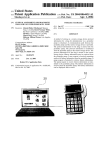
Chapter 8-2. Manual Operation (Pan / Tilt Control)
To control the pan and tilt movement of the dome simply use the joystick on the keyboard; to
pan the camera left push the joystick to the left, to tilt down pull the joystick down (towards
you). To move the dome faster push the joystick further in the that direction, the joystick is
proportional to the speed of the dome; a small movement will move the dome slower.
1
2
3
4
5
UP
Push the joystick forward, the camera tilt up.
DOWN
Push the joystick down (towards you), the camera tilt down.
LEFT
Push the joystick left, the camera pan left.
RIGHT
Push the joystick right, the camera pan right.
DIAGONAL
Push the joystick diagonally, the camera moves to that direction (direction
on figure 1)
Figure 1
Figure 2
Relationship Between Joystick and Direction
Relationship Between Joystick and Rotation Speed
Chapter 8.
33
Chapter 8-2-1. Fast Dome Selection
To call out a dome controlling or setting
* To select 1st Fast Dome
Push key 1 followed by CAM key.
* To select 64th Fast Dome
Push key 6 then 4 followed by CAM key.
When matrix system is used, select monitor before camera selection. Please refer to matrix
system user manual.
POWER
F1
F2
ESC
CAM ESC
AUX LIGHT
CAM SETUP
CTRL1
180 REV
CTRL2
LENS SPEED
WIPER
SPRAY
F3
AUTO
PAN
PWR
R/T
F1
ALARM
F2
F4
F3
PRESET1
F4
ALARM
RESET
1
2
3
SETUP
SEQ
4
5
6
MON
ZOOM
IN
ZOOM
OUT
CAM
FOUCS
FAR
FOUCS
NEAR
PRESET2
7
PRESET3
SET
FAST
8
CLR
0
9
ENT
PRESET
IRIS
C
IRIS
O
AUTO
FOUCS
DVR
MATRIX
AUTO
IRIS
SHIFT
CALL
WIPER
ON
MON
CAM
AUTO
PAN
1
2
3
AUTO
FOCUS
5
6
ZOOM
IN
ZOOM
OUT
8
9
FOCUS
FAR
FOCUS
NEAR
0
ENT
IRIS
O
IRIS
C
SEARCH
SEQ
4
SPRAY
CTRL1
CTRL2
7
180
CLR
DWELL
PIH-800II
EXIT
ESC
ALARM
RESET
LOCK
OFF
PRESET
AUTO
IRIS
PIH-801
Chapter 8-2-2. Zoom Lens Control
* To Zoom In
Push ZOOM IN key. The viewing angle becomes narrower and target will become enlarged on
the screen. Zooming will stop when the key is released.
* To Zoom Out
Push ZOOM OUT key. The viewing angle becomes wider and target will become smaller on
the screen. Zooming will stop when the key is released.
POWER
F1
F2
ESC
CAM ESC
AUX LIGHT
CAM SETUP
CTRL1
180 REV
CTRL2
LENS SPEED
WIPER
SPRAY
F3
F4
1
2
3
SETUP
SEQ
ALARM
RESET
4
5
6
MON
ZOOM
IN
ZOOM
OUT
CAM
FOUCS
FAR
FOUCS
NEAR
F3
AUTO
PAN
PWR
R/T
F1
ALARM
F2
F4
PRESET1
PRESET2
7
PRESET3
SET
FAST
8
CLR
0
9
ENT
PRESET
IRIS
O
IRIS
C
AUTO
FOUCS
DVR
MATRIX
AUTO
IRIS
SHIFT
PIH-800II
CALL
WIPER
LOCK
ON
OFF
EXIT
ESC
MON
CAM
AUTO
PAN
1
2
3
AUTO
FOCUS
PRESET
AUTO
IRIS
SEARCH
ALARM
RESET
SEQ
4
5
6
ZOOM
IN
ZOOM
OUT
SPRAY
CTRL1
CTRL2
7
8
9
FOCUS
FAR
FOCUS
NEAR
180
CLR
0
ENT
IRIS
O
IRIS
C
DWELL
PIH-801
Chapter 8-2-3. Focus Control
The focus function on Fast Dome can be set as Auto Focus or Manual Focus.
* Manual focus far
Push FOCUS FAR key.
The target will become farther. Focusing will stop when the key is released.
(PIH-801 keyboard LCD displays "F=M")
* Manual focus near
Push FOCUS NEAR key.
The target will become nearer. Focusing will stop when the key is released.
(PIH-801 keyboard LCD displays "F=M")
Chapter 8.
34
* Auto Focus
Push AUTO FOCUS key. The lens will automatically adjust itself for optimum focus.
(PIH-801 keyboard LCD displays "F=A")
POWER
F1
F2
ESC
CAM ESC
AUX LIGHT
CAM SETUP
CTRL1
180 REV
CTRL2
LENS SPEED
WIPER
SPRAY
F3
AUTO
PAN
PWR
R/T
F1
ALARM
F2
F4
F3
PRESET1
F4
1
2
3
SETUP
SEQ
ALARM
RESET
4
5
6
MON
ZOOM
IN
ZOOM
OUT
PRESET2
7
PRESET3
SET
FAST
8
CLR
0
9
ENT
CAM
PRESET
FOUCS
FAR
IRIS
O
FOUCS
NEAR
AUTO
FOUCS
IRIS
C
AUTO
IRIS
DVR
MATRIX
SHIFT
CALL
WIPER
ON
OFF
EXIT
ESC
MON
CAM
AUTO
PAN
1
2
3
AUTO
FOCUS
PRESET
AUTO
IRIS
SEARCH
ALARM
RESET
SEQ
4
5
6
ZOOM
IN
ZOOM
OUT
SPRAY
CTRL1
CTRL2
7
8
9
FOCUS
FAR
FOCUS
NEAR
180
CLR
0
ENT
IRIS
O
IRIS
C
LOCK
DWELL
PIH-800II
PIH-801
Chapter 8-2-4. Iris Control
The purpose of iris control is to adjust brightness on target. It can be set as Auto Iris or Manual Iris.
* Iris Open
Push IRIS O key, to open the iris and brighten the picture.
Iris will stop when the key is released. (PIH-801 keyboard LCD displays I=M)
* Iris Close
Push IRIS C key, to open the iris and reduce glare.
Iris will stop when the key is released. (PIH-801 keyboard LCD displays I=M)
* Auto Iris
Push AUTO IRIS key, to select the Auto Iris mode. (PIH-801 keyboard LCD displays I=A)
POWER
F1
F2
ESC
CAM ESC
AUX LIGHT
CAM SETUP
CTRL1
180 REV
CTRL2
LENS SPEED
WIPER
SPRAY
F3
AUTO
PAN
PWR
R/T
F1
ALARM
F2
F4
F3
PRESET1
PRESET3
F4
SET
ALARM
RESET
1
2
3
SETUP
SEQ
4
5
6
MON
ZOOM
IN
ZOOM
OUT
7
8
9
CAM
FOUCS
FAR
FOUCS
NEAR
PRESET2
FAST
CLR
0
ENT
PRESET
IRIS
O
IRIS
C
AUTO
FOUCS
DVR
MATRIX
AUTO
IRIS
SHIFT
PIH-800II
CALL
WIPER
LOCK
ON
EXIT
ESC
MON
CAM
AUTO
PAN
1
2
3
AUTO
FOCUS
5
6
ZOOM
IN
ZOOM
OUT
8
9
FOCUS
FAR
FOCUS
NEAR
0
ENT
IRIS
O
IRIS
C
SEARCH
ALARM
RESET
SEQ
4
SPRAY
CTRL1
CTRL2
7
180
CLR
DWELL
OFF
PRESET
AUTO
IRIS
PIH-801
Chapter 8-2-5. Horizontal 180 Instant Flip
Some times it is hard to use the joystick to control the camera tracking the target directly under
the camera. The instant flip key can rotate the camera 180 instantly. This allows the camera
continue to track the target passing directly under the camera.
Two ways to operate 180 instant flip:
1 Push 180 REV key on keyboard to flip the camera 180 horizontally.
CTRL 2
2 Push joystick down to bring the camera down to the end, release the joystick and quickly
push joystick down twice to flip the camera 180 horizontally.
Chapter 8.
35
Chapter 8-3. Preset Positions Setting
Each dome can have 128 individual preset positions. Each preset stores the exact position of
the camera and automatic pan, tilt ,zoom, focus and iris setting. Once the data is set, the preset
can be recalled for viewing, or the presets can be set for auto pan.
Only the first 16 preset positions of fast dome can be set to auto pan mode and first 6 preset
positions are corresponding with the 6 alarm inputs.
1 Selecting Fast Dome
*
Push key 1 followed by CAM key, confirming that first camera is selected.
Ex. To select 1st fast dome : 1 CAM keys
To select 64th fast dome : 6 4 CAM keys
2 Selecting Preset Position
*
Push key 1 followed by CAM key, confirming that first preset position selected.
: 1 PRESET keys
Ex. To select the 1st preset position
To select the 128th preset position : 1 2 8 PRESET keys
3
Joystick Control
Move the Joystick to bring the camera to the desired view position.
4
Adjusting Lens
ZOOM IN / OUT, FOCUS NEAR / FAR / AUTO and IRIS O / C / AUTO keys.
When set up preset point, using manual focus will provide both clarity and stability of image.
POWER
F1
F2
ESC
CAM ESC
AUX LIGHT
CAM SETUP
CTRL1
180 REV
CTRL2
LENS SPEED
WIPER
SPRAY
F3
F4
1
2
3
SETUP
SEQ
ALARM
RESET
4
5
6
MON
ZOOM
IN
ZOOM
OUT
CAM
FOUCS
FAR
FOUCS
NEAR
F3
AUTO
PAN
PWR
R/T
F1
ALARM
F2
F4
PRESET1
PRESET2
7
PRESET3
SET
FAST
8
CLR
0
9
ENT
PRESET
IRIS
O
IRIS
C
AUTO
FOUCS
DVR
MATRIX
AUTO
IRIS
SHIFT
PIH-800II
Chapter 8.
CALL
WIPER
LOCK
ON
OFF
EXIT
ESC
MON
CAM
AUTO
PAN
1
2
3
AUTO
FOCUS
AUTO
IRIS
SEARCH
ALARM
RESET
SEQ
4
5
6
ZOOM
IN
ZOOM
OUT
SPRAY
CTRL1
CTRL2
7
8
9
FOCUS
FAR
FOCUS
NEAR
180
CLR
0
ENT
IRIS
O
IRIS
C
DWELL
PIH-801
36
PRESET
5
Setting Preset Speed
The speed the dome travels to that preset position can be adjusted between 1 to 255 per
second (the factory default is 0 /sec).
* PIH-800II :
To set speed as 10 /sec: Push key 1 0 followed by F1 key, two beeps will be heard
confirming that speed is set.
* PIH-801 :
To set speed as 10 /sec : Push key 1 0 followed by F3 key.
POWER
F1
F2
ESC
CAM ESC
AUX LIGHT
CAM SETUP
CTRL1
180 REV
CTRL2
LENS SPEED
WIPER
SPRAY
F3
AUTO
PAN
PWR
R/T
F1
ALARM
F2
F4
F3
PRESET1
PRESET3
F4
1
2
3
SETUP
SEQ
ALARM
RESET
4
5
6
MON
ZOOM
IN
ZOOM
OUT
SET
PRESET2
FAST
7
8
9
CAM
FOUCS
FAR
FOUCS
NEAR
AUTO
FOUCS
CLR
0
ENT
PRESET
IRIS
O
IRIS
C
AUTO
IRIS
DVR
MATRIX
SHIFT
PIH-800II
CALL
WIPER
LOCK
ON
OFF
EXIT
ESC
MON
CAM
AUTO
PAN
1
2
3
AUTO
FOCUS
AUTO
IRIS
4
5
6
ZOOM
IN
ZOOM
OUT
PRESET
SEARCH
ALARM
RESET
SEQ
SPRAY
CTRL1
CTRL2
7
8
9
FOCUS
FAR
FOCUS
NEAR
180
CLR
0
ENT
IRIS
O
IRIS
C
DWELL
PIH-801
Note: When PIH-800II keyboard is used, push F1 key to confirm speed entered.
When PIH-801 keyboard is used, push F3 key to confirm speed entered.
6 Setting Preset Dwell Time
*
The dwell time means the time user wants to view on certain preset position under Auto Pan.
The Preset Dwell Time can be set between 0 ~ 255 seconds. (The factory default is 0 second)
If the dwell is set to 0 second then that position will be omitted from the Auto Scan Tour.
To set dwell to 5 seconds: Push key 5 followed by F2 key.
Ex. To set dwell to 5 second : 5 F2 keys
To set dwell to 10 second : 1 0 F2 keys
7 Storing Preset Data
*
Once the above steps have been completed, the information must be stored or it will not be
memorized by the system.
* PIH-800II :
Push key 1 followed by F3 key, two beeps will be heard confirming that data is stored.
* PIH-801 :
When PIH-801 is used, there is no need to perform data saving step for 1st ~ 16th preset.
For 17th ~ 128th presets F3 key should be pushed to store data.
Note : For the first 16 presets on each dome, the above steps must be repeated. For presets
17 ~ 128 there is a default speed and dwell setting so steps 5 and 6 are not required.
Chapter 8.
37
Chapter 8-4. Recalling Preset Positions
Once the required preset positions have been stored in a dome, they may be quickly recalled,
returning the dome to exact position.
* To recall 1st Preset Position: Push key 1 followed by PRESET key.
The dome will move to that position in speed of 360 /sec.
: 1 PRESET keys
Ex. To recall 1st preset position
To recall 128th preset position : 1 2 8 PRESET keys
POWER
F1
F2
ESC
CAM ESC
AUX LIGHT
CAM SETUP
CTRL1
180 REV
CTRL2
LENS SPEED
WIPER
SPRAY
F3
AUTO
PAN
PWR
R/T
F1
ALARM
F2
F4
F3
PRESET1
PRESET3
F4
1
2
3
SETUP
SEQ
ALARM
RESET
4
5
6
MON
ZOOM
IN
ZOOM
OUT
SET
PRESET2
FAST
7
8
9
CAM
FOUCS
FAR
FOUCS
NEAR
AUTO
FOUCS
CLR
0
ENT
PRESET
IRIS
O
IRIS
C
AUTO
IRIS
DVR
MATRIX
SHIFT
CALL
WIPER
ON
OFF
EXIT
ESC
MON
CAM
AUTO
PAN
1
2
3
AUTO
FOCUS
AUTO
IRIS
4
5
6
ZOOM
IN
ZOOM
OUT
PRESET
SEARCH
ALARM
RESET
SEQ
SPRAY
CTRL1
CTRL2
7
8
9
FOCUS
FAR
FOCUS
NEAR
180
CLR
0
ENT
IRIS
O
IRIS
C
LOCK
DWELL
PIH-800II
PIH-801
Chapter 8-5. Setting Preset Group
The purpose of setting preset group allows the management of the 16 preset positions before
Auto Scanning. The first 16 preset positions of each dome are separated into 4 groups. Preset
group must be set for the auto pan reference.
Group 1 includes: 1st 2nd 3rd and 4th preset positions.
Group 2 includes: 5th 6th 7th and 8th preset positions.
Group 3 includes: 9th 10th 11th and 12th preset positions.
Group 4 includes: 13th 14th 15th and 16th preset positions.
* To set up group 1: Push key 1 followed by F4 key.
Ex.
PIH-800II
PIH-801
1
1
3
1
2
1
To set Group 1
To set Group 2,3
To set Group 3,4
To set Group 1,2,3
To set Group 2,3,4
To set Group 1,2,3,4
POWER
F1
F2
ESC
CAM ESC
AUX LIGHT
CAM SETUP
CTRL1
180 REV
CTRL2
F4
2 F4
4 F4
2 3 F4
3 4 F4
2 3 4 F4
LENS SPEED
WIPER
SPRAY
1
2
3
1
2
9
F4
3 F4
4 F4
2 3 F4
3 4 F4
9 9 F4
F3
AUTO
PAN
PWR
R/T
F1
ALARM
F2
F4
F3
PRESET1
PRESET3
F4
SET
ALARM
RESET
1
2
3
SETUP
SEQ
4
5
6
MON
ZOOM
IN
ZOOM
OUT
7
8
9
CAM
FOUCS
FAR
FOUCS
NEAR
CLR
0
ENT
PRESET
IRIS
O
IRIS
C
DVR
MATRIX
AUTO
IRIS
SHIFT
PIH-800II
Chapter 8.
CALL
WIPER
LOCK
EXIT
MON
CAM
AUTO
PAN
1
2
3
AUTO
FOCUS
ALARM
RESET
SEQ
4
5
6
ZOOM
IN
ZOOM
OUT
SPRAY
CTRL1
CTRL2
7
8
9
FOCUS
FAR
FOCUS
NEAR
180
CLR
0
ENT
IRIS
O
IRIS
C
ESC
AUTO
FOUCS
OFF
SEARCH
PRESET2
FAST
ON
DWELL
PIH-801
38
PRESET
AUTO
IRIS
Chapter 8-6. Changing Preset Data
In order to change any preset position from the one stored, the dome must first be sent to that
preset position.
To change the 4th preset position of the Dome number 3, perform the following steps:
1 Push 3 CAM to select Dome 3
2 Push 4 PRESET to go to 4th preset position
3 Move joystick to bring camera to the desired view position.
4 Adjusting lens
5 Setting preset speed
6 Setting dwell time
7 Store Data
(Please refer to page 40-41 for step ~ )
Chapter 8-7. Activating Auto Pan
When the Auto Pan function is activated, the fast dome will auto touring the preset groups entered.
* To activate Auto Pan:
Push AUTO PAN key, confirming the activation of autopan.
(When use PIH-800II, Auto Pan Led will be lit. When use PIH-801, LCD will display F=A)
* To stop Auto Pan:
Push AUTO PAN key again, confirming the stop of autopan.
(When use PIH-800II, Auto Pan Led will be Off. When use PIH-801, LCD will display F=M)
POWER
F1
F2
ESC
CAM ESC
AUX LIGHT
CAM SETUP
CTRL1
180 REV
CTRL2
LENS SPEED
WIPER
SPRAY
F3
AUTO
PAN
PWR
R/T
F1
ALARM
F2
F4
F3
PRESET1
F4
ALARM
RESET
1
2
3
SETUP
SEQ
4
5
6
MON
ZOOM
IN
ZOOM
OUT
CAM
FOUCS
FAR
FOUCS
NEAR
PRESET2
7
PRESET3
SET
FAST
8
CLR
0
9
ENT
PRESET
IRIS
O
IRIS
C
AUTO
FOUCS
DVR
MATRIX
AUTO
IRIS
SHIFT
PIH-800II
CALL
WIPER
LOCK
ON
EXIT
ESC
MON
CAM
AUTO
PAN
1
2
3
AUTO
FOCUS
5
6
ZOOM
IN
ZOOM
OUT
8
9
FOCUS
FAR
FOCUS
NEAR
0
ENT
IRIS
O
IRIS
C
SEARCH
ALARM
RESET
SEQ
4
SPRAY
CTRL1
CTRL2
7
180
CLR
DWELL
OFF
PRESET
AUTO
IRIS
PIH-801
If the AUTO PAN is activated, no other commands can be sent to that dome, but other dome
can still be selected and operated manually.
* To select (call out) another dome while it is under Auto Pan mode:
Simply push the numeric key followed by the CAM key.
Push key 2 followed by CAM key, confirming the 2nd camera is selected.
Chapter 8.
39
Chapter 8-8. Deleting Preset Data
Sometimes it is necessary to delete the stored data. All the data can be cleared from a dome by
pressing key 9 0 1 1 , followed by the CLR key.
All 128 preset data will be erased.
* Push 9 0 1 1 , followed by CLR key.
POWER
F1
F2
ESC
CAM ESC
AUX LIGHT
CAM SETUP
CTRL1
180 REV
CTRL2
LENS SPEED
WIPER
SPRAY
F3
F4
1
2
3
SETUP
SEQ
ALARM
RESET
4
5
6
MON
ZOOM
IN
ZOOM
OUT
CAM
FOUCS
FAR
FOUCS
NEAR
F3
AUTO
PAN
PWR
R/T
F1
ALARM
F2
F4
PRESET1
PRESET2
7
PRESET3
SET
FAST
8
CLR
0
9
ENT
PRESET
IRIS
O
AUTO
FOUCS
IRIS
C
DVR
MATRIX
AUTO
IRIS
SHIFT
CALL
WIPER
LOCK
PIH-800II
ON
OFF
EXIT
ESC
MON
CAM
AUTO
PAN
1
2
3
AUTO
FOCUS
PRESET
AUTO
IRIS
SEARCH
ALARM
RESET
SEQ
4
5
6
ZOOM
IN
ZOOM
OUT
SPRAY
CTRL1
CTRL2
7
8
9
FOCUS
FAR
FOCUS
NEAR
180
CLR
0
ENT
IRIS
O
IRIS
C
DWELL
PIH-801
Chapter 8-9. Alarm Management
The 6 alarm inputs of each fast dome are corresponding with the first 6 preset positions. When
an alarm signal is triggered, the dome will go to the relevant position at 360 /sec. Make sure
the first 6 preset positions are set to desired alarm areas.
Alarm input can be set to NC (normally close) or NO (normally open) depends on alarm detector.
Please refer to page 7 for alarm switch setting.
* Relationship Between Alarm Inputs and First 6 Presets
l Alarm Input 1 will send the dome to Preset Position 1
l Alarm Input 2 will send the dome to Preset Position 2
l Alarm Input 3 will send the dome to Preset Position 3
l Alarm Input 4 will send the dome to Preset Position 4
l Alarm Input 5 will send the dome to Preset Position 5
l Alarm Input 6 will send the dome to Preset Position 6
Chapter 8-9-1. Alarm Response Mode
The fast dome alarm response can be set to Lock or Release mode.
: dome remains at last alarmed preset point
Lock
Release : dome moves between alarmed points then reverts to prior status, such as autopan.
1 Lock Mode
l
When an alarm is triggered, the dome will go to the relevant position at 360 /sec and the
keyboard will audio alert the user until it is canceled manually.
To manually cancel the alarm trigger: Push ALARM RESET key.
If more than one alarm is triggered, the fast dome will lock on the last alarm triggered position.
Chapter 8.
40
2 Release Mode
l
l Under Auto Pan Condition
When an alarm is triggered under Auto Pan, fast dome will go to the relevant position
at 360 /sec. After 60 seconds the alarm will be canceled automatically and back to
Auto Pan mode. If more than one alarm is triggered, the fast dome will moves between
alarmed points every 5 seconds and back to Auto Pan mode after 60 seconds.
l Not Under Auto Pan Condition
When an alarm is triggered not under Auto Pan, the fast dome will go to the relevant
position at 360 /sec. After 60 seconds the alarm will be canceled automatically, and
dome will be back to first preset position. If more than one alarm is triggered, the fast
dome will move between alarmed points every 5 seconds and back to first preset
position after 60 seconds.
l The audio alert for alarm trigger will remain on until it is manually canceled by push
the ALARM RESET key.
Chapter 8-9-2. Alarm Output
Each fast dome has 1 alarm output, with three contacts: Common, NC (normally close) and NO
(normally open) to activate linking devices.
l When alarm response mode is set to LOCK Mode:
When the alarm is triggered, NC contact to Common will be open and NO contact to
common will be close. Alarm output will be back to the condition before alarm, 10
seconds after the last alarm is triggered.
l When alarm response mode is set to RELEASE mode:
When the alarm is triggered, NC contact to Common will be open and NO contact to
common will be close. Alarm output will be back to the condition before alarm, 60
seconds after the last alarm is triggered.
Chapter 8.
41
Chapter 9.
HOW TO USE IP FAST DOME HOME PAGE
Chapter 9-1. Browsing Video Home Page
Start your Web browser and enter the URL (e.g. Http://211.21.33.44) in the Address field.
The Home page of the IP Fast Dome is now displayed:
* Video Size
You can adjust the video size and the appearance on the screen with the following sizes.
Video Size
Small (QCIF)
Default (CIF)
Large (FULL)
NTSC Video
176 x 112
352 x 240
704 x 480
PAL Video
176 x 144
352 x 288
704 x 576
Note : NTSC (60Hz) is the common standard in the USA, where as PAL (50Hz) dominates in
Europe.
* Snapshot
Take a picture from the viewing video.
* Configure
Click to Configuration pages of IP Fast Dome.
Chapter 9.
42
Chapter 9-2. IP Fast Dome Configuration Page
The Configurations of the IP Fast Dome are now presented as links in the margin of the
Configuration Page. Simply click the relevant link for the settings you want to configure.
Server Configurations
Functions
General
User
Clock
System
Description
Set various information about the server name and the language, etc.
Create and delete users and passwords.
Set the product Date and Time.
Provide commands for resetting to the factory default settings,
restarting the system, and saving configurations to flash memory
for permanently stock.
Network Configurations
Functions
General
DHCP
DDNS
Chapter 9.
Description
Assign and IP Address and configure the relevant network
parameters to the server.
DHCP (Dynamic Host Configuration Protocol) is a protocol that
lets network administrators centrally manage and automate the
assignment of Internet Protocol (IP) addresses in an organization's
network.
The DDNS (Dynamic Domain Name Service) is used to access IP
Fast Dome with an easy memorized name such as
http://demo.ddns.meritlilin.com instead of http://211.21.33.44
43
I/O Configurations
Functions
Serial
GPIO
PTZ Device
Description
Select the operational modes for COM1 and COM2.
General Purpose Input/Output. These are for event triggers and
actions.
Select the driver that corresponds to your PTZ device and control
the PTZ device.
Video Configurations
Functions
Time Stamp
Quality
Description
Show time and text on the video.
Adjust the video quality and compression level.
Event Configurations
Functions
Motion
Script Edit
Description
Create and enable in-picture motion detection windows.
These are used to trigger alarms whenever significant movement
occurs in the detection windows.
The Script Editor offers advanced administrators and developers
with an even greater level of flexibility for customizing the
application specifically to meet their user needs. Using the on-line
help as a reference, advanced users follow the instructions below to
quickly develop programming scripts for time and / or
alarm-triggered events.
Chapter 9-3. Server Configurations
Chapter 9.
44
* Name : Specify server name.
This name setting is also used by Merit Li Lin DDNS service to
recongize each server (see below DDNS Settings), e.g. If configure name as company.user
to DDNS address ddns.lilin.com, then this IP Fast Dome can be accessed by URL
http://company.user.meritlilin.com after register to DDNS server.
* Owner : Specify server owner.
* Owner Email :
If Return mail address when using SMTP mail delivery is not specified correctly, some
security SMTP server may reject the delivery of this mail.
* MAC Address :
Display MAC address information for this Network Camera. It's read only.
* Firmware Version : Display firmware version information.
* Language : Alternative language option.
User may change the language of web contents for different application.
* Large size image using the true resolution :
You can set the Large image to use an interlaced image, or not.
* Live video using :
You can select the ActiveX for better performance in MS Internet Explorer, or select the
Java Applet for more browsers comparability.
Chapter 9-4. User Settings
IP Fast Dome provides 3-layer user security control as below:
* Open for All is a factory default when no user enters in User Configuration, it allows any
user over Internet to monitor and configure the Network Camera.
Chapter 9.
45
* "Restricted User" is the user in User Configuration without administration permission. The
user can be configured to have limited permission to see video, for example, capable of
changing video size, etc.
* "Administrator User" is the user in User Configuration with administration permission. The
user has all permission to operate the Network Camera, such as managing, configuring, and
upgrading the software.
Append New User
* Name : New user name to login.
* Password : Password for above user.
* Confirm Password : Type again to confirm password.
* Permission to : Indicate above user has any permission to:
* Administration : If no, then user can not enter administration page.
Note : That the first user shall set and get administration privilege; otherwise, he can not get
into administration page any more. If this happened, he must use emergency factory
default to clean all users.
* Change Video Size : If no, only CIF size is allowed.
* Submit to add above new user into list.
* Cancel to abort above operation.
When entering "submit" at first time, Network Camera will ask for a new administrator to
login in.
Once getting users in list, then you could choose users in list to make modification (update),
or remove specified user.
Click "Save Changes" bottom if needed for existing data changed in Network Camera when
power off.
Chapter 9.
46
Chapter 9-5. Clock Settings
The built-in real-time clock of IP Fast Dome provides accurate date/time of system even when
power off.
For different time zone or long period operation, you may need to adjust the clock --- just enter
Time and Date information then click Submit.
Click "Set as PC clock" bottom to set the date/time of the IP Fast Dome as your PC's.
Click "Save Changes" bottom if needed for existing data changed in Network Camera when
power off.
Chapter 9-6. System Commands
* Load Default : The Load Default retrieves all except network setting.
Note : The factory default just recovers the working setting but it isn't saved to permanent
memory (will back to previous setting after boot). To change the boot settings, you must
set "Save Changes".
* Save Changes : Save the working setting to permanent memory that will retrieve after reboot.
* Reboot System : Force IP Fast Dome to restart.
Chapter 9.
47
Chapter 9-7. Network
* IP Address : IP Fast Dome IP address.
* Subnet Mask : Subnet mask of you LAN. Note that the IP Address above and Gateway IP
Address below should be in the same subnet.
* DNS IP Address : Domain name server information is to allow IP Fast Dome to contact
external server with mnemonic domain name (e.g. ftp.MERITLILIN.com) instead of
numeric IP address (e.g. 168.95.1.1).
* Gateway IP Address : IP Fast Dome traffic to Internet should go through Gateway, if not
setting this, only Intranet (LAN) can be accessed.
* HTTP Connection Port : Specify the HTTP web server listen port for client (browser)
connection. Default uses port 80 (HTTP standard port), valid range from 0~65535.
Note : Before changing the listen port, user must add a port directive ":" in browser URL in
order to get correct connection.
(i.e. http://<IP>:<Port> , e.g. http://192.168.0.200:80000 to access IP Fast Dome
with IP 192.168.0.200 and port with 8000).
These features enable user to use IP Fast Dome behind NAT or IP Sharing devices which could
access up to 65536 IP Fast Dome with one IP Address.
The factory default won't change the IP Address and Port setting. Once forgetting the specified
port of your IP Fast Dome, you must use ARP & Ping setting (see Assign IP Address by ARP)
to restore the port setting back to 80.
Click " Submit " bottom if needed, then IP Fast Dome will automatically store the setting and
reboot system (within 5 seconds to complete boot sequence) to take the setting effective.
Chapter 9.
48
Chapter 9-8. SMTP Settings
* Sender s Email Address: Your E-mail address.
* SMTP Server Address: SMTP server IP address.
* Authentication: If the SMTP Server has enabled authentication function. You have to fill up
the User Name and Password to pass through the authentication. IP Address : IP Fast Dome
IP address.
Chapter 9-9. DHCP Settings
* DHCP Settings : If there is a DHCP server installed on your LAN, you can enable DHCP to
automatically obtain network settings such as IP address subnet mask, default gateway, and
DNS servers. Because the assigned IP address can be dynamically changed every time it
obtains from the DHCP server, we provide a method called IP Notification to notify users
that which IP address is acquired.
* IP Notification by FTP : If a FTP server is installed on your network, you can enable this
option to obtain the newly assigned IP address of your IP Fast Dome. A HTML file named
NewIP_xxxxxx.htm will appear under the upload path for you to link to IP Fast Dome,
where xxxxxx is the last six digits of the serial number.
* Login Name : Name of your FTP account.
* Password : Password used to login your FTP account.
Chapter 9.
49
* Upload Path : Path to put the file.
* IP Notification by E-mail : With this option enabled, your IP Fast Dome will send E-mail to
you as soon as it obtains the IP address from DHCP.
* Recipient : Your E-mail address.
* Message subject : Subject of this E-mail.
Chapter 9-10. DDNS Settings
The DDNS (Dynamic Domain Name Service) is used when users want to access IP Fast Dome
with an easy memorized name such as http://demo.ddns.meritlilin.com instead of
http://61.220.235.172.
This service could be useful when IP Fast Dome is located behind Dial-up ADSL or IP sharing
devices, which does not have fix IP address, then it's impossible to reach IP Fast Dome from
Internet.
The mechanism of DDNS service is described as below :
1. When IP Fast Dome enables the DDNS service, it will "register" to DDNS server with its
information, such as server name to access, router virtual port number and updated
frequency, etc.
2. Then IP Fast Dome automatically "update" to DDNS server by a fix frequency, so even IP is
changed by ISP, the DDNS server still could get and update internal database.
Then, once users access from Internet with its register name, e.g. If registering with server
name "demo" to DDNS server "ddns.meritlilin.com", IP Fast Dome could be accessed by
http:// demo.ddns.meritlilin.com.
Note : The DDNS service is proprietary, which only works with DDNS server and LILIN
brands products.
* Dynamic DNS Activate : Click on to activate DDNS service.
* Dynamic DNS Address : Specify address of DDNS server, and the default is
"ddns.meritlilin.com"
Chapter 9.
50
* Dynamic DNS Port : Specify DDNS server listen port, and the default is 80.
* Router Incoming Port : Specify your router listen port for DDNS server to redirect.
The router may configure the different port for incoming (Internet request) and outgoing
(Intranet request), e.g. it may configure to redirect Internet HTTP (port 80) request to
Intranet port 8000, then, in this case, we must configure the "Router Incoming Port" to 80,
and inside the IP Fast Dome Network settings should set HTTP port with 8000.
* Update Time : Specify the IP Fast Dome updated frequency in seconds, and the default is
600 (10 minutes), this is interval that IP Fast Dome will automatically send an updated
packet to DDNS server.
* DDNS message : Return message from remote DDNS server, and some hints may help to
diagnostic the reason if register fails.
ddnsaddr CGI fail : It means that IP Fast Dome can't communicate with Internet world.
Make sure your Network Configuration has correct subnet mask and default gateway, and
DNS1 setting is correct and reachable.
Already registered : Another user had registered this name; please change your register
name by changing "server name" in chapter Server General Settings.
Example : To setup a IP Fast Dome (IP address 192.168.0.200) behind a dialup ADSL router,
and wish to access by name http://demo.ddns.meritlilin.com .
And the procedure is as below :
Configure the ADSL router with PPPoE enable; Lan IP, 192.168.0.254; and subnet mask,
255.255.255.0.
Assign the ADSL router's virtual server with service port 80 to server IP 192.168.0.200.
Configure network configuration with IP address 192.168.0.200; subnet 255.255.255.0;
DNS1 with valid DNS address such as 168.95.192.1 or 168.95.1.1; gateway IP address
with 192.168.0.254 (router's IP); HTTP port with port 80.
Configure server name in chapter Server General Settings with demo.
Configure DDNS with Activate; Address "ddns.meritlilin.com"; DDNS with port 80;
Router Incoming port 80; and update time with 600 (10 minutes). Finally, click submit.
If DDNS message success, then enter URL http://demo.ddns.meritlilin.com on browser.
Consequentially, it will show IP Fast Dome's home page.
Click " Save Changes " bottom if needed for existing data changed in IP Fast Dome when power
off.
Chapter 9.
51
Chapter 9-11. GPIO Status
Display the GPIO (General Purpose Input / Output) status. The GPIO Terminal Block /
MINI DIN provides control signal input and output, which includes four GPIO inputs, one
GPIO output as Relay junction. See Appendix E I/O & COM port for the detailed description.
* Set the relay : click the radio button to set the relay to ON or OFF.
Chapter 9-12. PTZ Adjustment
* Cam[n] Type : To select the PTZ devices. Contact your distributor / dealer to get supporting
model in formation of PTZ camera.
* Speed : To select the PTZ speed grade from 1 (slowest) to 10 (fastest).
* Preset Position/Name : There are 20 records of each individual sources, user could put their
favorite position with catchy name.
* PTZ Panel : Control the PTZ devices Zoom in/out, Pan left/right, and Tilt up/down.
Chapter 9.
52
Chapter 9-13. Video Setup
Time Stamp
Display Time Stamp & Text over the video just click on the these check boxes.
* Display Time check box : Display the Time Stamp.
* Display Text check box : Display text block. Full in the text string to display.
The valid characters are "a~z", "A~Z", "0~9", "!", "@", "#", "$", "%", "&", "*", "(", and ")"
To change the location of Time/Text, just full in the X and Y coordinate.
Note : The maximum display block area (Time + Text) are 12x4 characters.
String length more than 12 will feed to next line, and totally 4 lines available. More than
4 lines will strip off.
Chapter 9-14. Video Adjustment
Chapter 9.
53
The IP Fast Dome is capable of detecting NTSC/PAL automatically, video signal active/lose,
fully automatic (plug & see) and don't need any user configuration.
* Quality Adjustments :
To adjust video contrast, brightness, hue, color saturation, and quality. Note that the quality
level affects compression ratio and file size of video.
Resolution
NTSC
File Size (kb)
Max fps
Resolution
PAL
File Size (kb)
Max fps
4CIF (704x480)
CIF (352x240)
7 - 160
2 - 50
3
30
4CIF (704x576)
CIF (352x288)
9 - 200
2 - 60
3
25
(The Maximum performance is given in signler user and only one video source in use.)
* Frame Delay : To set the delay time between frames.
The unit of delay time is 10 microseconds. You can limit the output bandwidth via setting the
frame delay to do the flow control of the video stream. When the value is set to 0, it means no
limitation on the video stream.
Click " Save Changes " bottom if needed for existing data changed in Network Camera when
power off.
Chapter 9-15. Event Management
Motion Area Selection
Chapter 9.
54
* Motion Detection Region Selection :
Move the mouse to the regions in video window with white blocks to determine the motion
trigger areas.
After setting with clicking the left button of the mouse, the selected areas will be burned to
red blocks.
Chapter 9-16. Event Edit
Application developers wish to have different levels of customization within their own
applications. The may build through event manager, the event system provides several trigger
sources and action types which allow administrators to record the emergency images, such as
Motion detection, IO control, FTP or EMAIL to outside world.
It's easy to process --- just fill and submit a simple form.
The IP Fast Dome's event manager provides event control through programmable Event Scripts
which are the combination of several events.
Each event works simultaneously. If one of the trigger conditions in event script is satisfied,
then corresponding action will start to execute accordingly. A comprehensive set of "trigger
conditions" and "action commands" allowed to fit in varies of applications without limitation.
Note : The programmable event script has been supported since firmware version 2.0. Please
check out your currently firmware version in chapter Server General Settings.
Chapter 9.
55
To start the event manager, simply click Event icon, the event frame will pop up as below :
Upper edit window, middle status box, lower message window, and bottom control icons
mainly separate the event frame.
There are two ways to enter the event script. One is to use " Script Wizard " which just follows
the procedure to fill up some items. And, it will generate and append new script code to edit
window. The other one is to edit the form manually, which is for experienced users that want to
deeply control the functionalities of event operation.
Please refer to " Event Script Programmers Guide " which could download from
http://www.meritlilin.com for detail syntax and options description.
* Event Script Edit : Text window to enter event script manually.
* Event Status : Indicate the event status, "Stop Now" or "Start Now".
* Message : A window to show the results when below command icon pressed --- normally
will show "OK", "Parsing", "Fail", Or "Err String" which indicates the syntax error of
parsing, and starts from the error position in the script.
* Save Script : Command to save and parse current scripts in the "Event Script Edit" window.
If any syntax errors are detected, the error message, indicating the starting position of syntax
error, will be shown in the "Message" window.
* Event Auto Start when Power On :
The flag is to set the event script auto start-up when the system is powered on.
Note : Any change in "Event Script Edit" window must "Save Script" before "Start Script",
otherwise, the new changes will be lost and won't take effective.
Also the changes won't be saved into permanent memory unless you click the "Save
Changes" button in main Administration panel.
* Clear : Command to clean up "Event Script Edit" window.
* Start Script : Command to start the script execution.
* Stop Script : Command to stop the script execution.
* Script Wizard : Command to start the script wizard.
It helps user to make simple script automatically by wizard, but the wizard supports only
partial trigger and action commands.
To fully leverage the complete functionalities of event script, please refer to "Event Script
Programmers" Guide.
* Set Motion Detection Area : In order to activate the motion detection, you must choose the
detection area and start the motion detection script manually or by wizard.
* Help : Script Help lists all the syntax of trigger and action commands.
Chapter 9.
56
Chapter 10.
SPECIFICATION
Operational
Manual Pan / Tilt Speed
Preset Position Pan / Tilt Speed
Preset Position Dwell Time
Recall Preset Position Pan / Tilt Speed
180 Instant Flip Rotation Speed
Pan Rotation
Tilt Rotation
Pan / Tilt Accuracy
Preset Position
Preset Group
0.18 ~ 180 /sec (8 stages)
1 ~ 255 /sec
1 ~ 255 secretary
360 /sec
360 /sec
360 Continuous
-5 ~ +95
+ 0.25
128 preset positions (memory)
4 Group
(Corresponding with first 16 presets)
1 ~ 64 ID setting
Address Setting
Camera
Image Device
Horizontal & Vertical Pixel
1/4 Inch Interline Transfer CCD
NTSC (811x508) PAL (795x596)
NTSC (768x494) PAL (752x582)
2:1 Interlace
17X/22X : 480 TV Lines
25X : 570 TV Lines (Monochrome)
Scanning System
Horizontal Resolution
480 TV Lines (Color)
17X : 0.3Lux at F1.4
22X : 0.3Lux at F1.6
25X : 0.01Lux at F1.6 (Monochrome)
Minimum Illumination
0.1Lux at F1.6 (Color)
>50dB (AGC OFF)
Internal
NTSC (15.734KHz/60Hz)
PAL (15.625KHz/50Hz)
17X/22X : ON (20dB) / OFF (8dB)
25X : Low(8dB) / Medium(22dB) / High(36dB)
ON (Background Adjustable) / OFF
17X/22X : Fix
25X : Top / Bottom / Left / Right / Center
25X : On / Off / Auto
17X/22X : Auto / Outdoor / Indoor
25X : 2 Auto mode / Outdoor / Indoor
S / N Ratio
Synchronization
Horizontal & Vertical Synchronization
Auto Gain Control
Back Light Compensation
Back Light Compensation Zone
Sensitivity Up
White Balance
Video Output
Chapter 10.
CVBS 1.0Vpp 75
57
Network
CPU
ROM
RAM
Watch Dog
LED
Image Compression
Video Adjustment
Protocols
Max. Resolution
Performance
Event Trigger & Action
Installation
Software Upgrade
System Requirement
Security
Chapter 10.
32Bits RISC Processor
2M Bytes Flash ROM
16M Bytes SDRAM
Chip to monitor out tolerance system voltage and
abnormal program execution.
Two LEDs to indicate network and power/system
status GPIO with fully photo-isolated four alarm
inputs and one relay output.
JPGE ; Motion JPEG
Brightness, Contrast, Hue, Saturation, Quality
Level adjust for individual video channel.
TCP/UDP/IP, ARP, ICMP, HTTP, FTP, Telnet,
SMTP, DHCP, PPP
Single : NTSC (704 x 480) PAL (704 x 576)
Quad : NTSC (352 x 240) PAL (352 x 288)
Video through put :
Up to 30 frames/second.
Network through put :
Max. Up to 800K Bytes/second.
Programmable Event Script with Wizard supported.
Triggered by : Time (Frequency) / GPIO Input /
Motion Detection / Video / Network
Connection / CGI etc.
Action : Store image to internal buffer; FTP image
to remote site; E-mail image to specify account;
HTTP server push to remote site; relay output to
control external devices; etc.
Assign IP address : using ARP or Via Admin Web
Page or IP Installer.
Local or Remote software up-gradable using FTP
Custom web contents updated via FTP & Telnet.
Standard browser such as Microsoft IE4.x or 5.x or
above, and Netscape Navigator 4.x running on
Win95/98/NT, Linux, etc.
Three-layer Password Protection
58
Optical Lens
17X Lens Focal Length
17X Lens Aperture Max
17X Horizontal View Angle
22X Lens Focal Length
22X Lens Aperture Max
22X Horizontal View Angle
25X Lens Focal Length
25X Lens Aperture Max
25X Horizontal View Angle
Focus Control
f = 3.9 ~ 66.3mm
F1.4 (wide) ~ F3.6 (telephoto)
50.9 (wide) / 4.2 (telephoto)
f = 3.9 ~ 86mm
F1.6 (wide) ~ F3.6 (telephoto)
50.9 (wide) / 2.4 (telephoto)
f = 3.8 ~ 95.0mm
F1.6 (wide) ~ F3.7 (telephoto)
51.9 (wide) / 2.2 (telephoto)
17X/22X : Auto / Manual
25X : Auto / One Shot / Manual (3 selections)
17X/22X : Auto / Manual
25X : Auto / Manual (2 selections)
Manual Control
+ 5%
Iris Control
Zoom In / Out
Zoom In / Out Accuracy
Electrical
Power Supply
Input Voltage
Power Consumption
Network Interface
Control Interface
RS-485 Voltage
Alarm Input
Alarm Input Voltage
Alarm Output
Alarm Output Voltage
Alarm Response Mode
24Vac or 90Vac ~ 260Vac (Option)
12Vdc
13W
1 RJ-45 for Ethernet (10 Base-T)
RS-485 (1 Input / 1 Output)
5.6V
6 Inputs (Pull up)
5.6V
1 Output (NC or NO mode)
0.5A 120Vac / 1A 24Vdc
Lock or Release Mode
Environmental
Operation Temperature
Operation Humidity
-5 C ~ +50 C
0% ~ 90%
Mechanical
Height
Diameter
Weight (Fast Dome Alone)
Weight (With External Housing)
Chapter 10.
208mm (8.3")
145mm (5.6")
2.5Kg
5Kg
59
External Housing
Electrical
Power Supply
Input Voltage
Power Consumption
Control Interface
RS-485 Voltage
Alarm Input
Alarm Input Voltage
Alarm Output
Alarm Output Voltage
24Vac or 90Vac ~ 260Vac (Option)
12Vdc
7.5W
RS-485 (1 Input / 1 Output)
5.6V
6 Inputs (Pull up)
5.6V
1 Output (NC or NO mode setting)
0.5A 120Vac / 1A 24Vdc
Environmental
Operation Temperature
Operation Humidity
-20 C ~ +50 C
0% ~ 90%
Mechanical
Height
Diameter
Weight (Housing Alone)
Weight (With Fast Dome)
Chapter 10.
340mm (13.4")
250mm (9.8")
2.5Kg
5Kg
60
Appendix A.
Upgrading the Software
IP Fast Dome software is contained in Flash Memory, a silicon chip allowed to be erased and
re-written. It provides an easy way to update the software without change any parts; just simply
load the newest software from network.
The following procedures are to update the software :
* Check software version
Enter URL "http://<IP Fast Dome IP address>/ver" in your web browser, which will show you
the software version.
Example :
Enter "http://192.168.0.200/ver" in Microsoft IE5 URL location, you will see the software
version -- "Software Version = 1.11 Revision 0905.1641", which indicates the currently
software version is 1.11.
Note : You can also get the software version in configurations page in chapter Server General
Settings.
* Obtain the software (flash.bin)
The latest version of the IP Fast Dome software is free of charge from LILIN Corporation or
your local distributor. Also you can obtain this software over the Internet.
URL : http://www.meritlilin.com.
* Upgrade procedure via FTP
Download the newest software and unzip it into your local Driver, for example "C:\temp".
Then, confirm the "flash.bin" file exists in this directory.
Remove all event setting and Reset the IP Fast Dome :
You have two ways to remove the event scripts. One is to choose "Clear" and to use "Save"
icon on "Event Script Edit" page to set the event script to empty.
The other is to click the "Load Default" icon in "Server / System" page to reset all settings,
however, it will not only delete events, but also all other settings.
Then click the "Reboot System" to restart the Network Camera or enter CGI command URL
"http://<IP Fast Dome IP address>/control?reboot=1" in your web browser.
Caution : You must remove all events and reboot the network camera before doing the
following procedure; otherwise, some occasional internal conflicts may
endanger the Flash devices.
* Start the FTP session and log in to the IP Fast Dome
For example, in our case for Windows98 :
Enter DOS by "start Program MS-DOS Prompt".
Change to directory where the latest flash.bin exist.
Start ftp session by enter "ftp <IP Fast Dome IP Address>".
Enter "root" as USERNAME, "pass" as PASSWORD if no user in User List record. In case
any user list exists, you will have to use your administrator's USERNAME and
PASSWORD to login.
Appendix A.
61
* Set FTP to binary mode using the command "bin".
In FTP session window, Enter "bin".
* Upload the software into IP Fast Dome by FTP "put" command.
In FTP session window, enter "put flash.bin".
In FTP session window, enter "bye" to quit FTP session.
* FTP session may freeze for around 1 minute to transfer and automatically upgrade the
software. During that time, ping the IP Fast Dome until get constant reply, which means
system had complete upgrading and rebooting, then open browser to verify the software
version been updated.
Note : If FTP session quits immediately after issued by command, you should continue
pining IP Fast Dome instantly. If IP Fast Dome replies to the ping command right after
pinging, it means IP Fast Dome may not enter the self-programming stage to verify the
software version. If not updated, then you should reboot IP Fast Dome and back to
step 3 try again.
C:\temp> ftp 192.168.0.200
Connected to 192.168.0.200
220 192.168.0.200 MERIT LILIN FTP server (ARM BEV 3.0.H)
ready.
User (192.168.0.200 : (none)) root
331 Password required for root.
Password:
<=enter pass as default
230 User root logged in.
ftp> bin
200 Type set to I.
ftp> put flash.bin
200 PORT command successful
150 Opening BINARY mode data connection for flash.bin
226 Transfer complete.
ftp: 2097152 bytes sent in 10.11 Seconds 207.43Kbytes/sec.
ftp: bye
221 Goodbye.
<=Quit ftp session immediately
<= if the window is frozen, please open another
dos session
Appendix A.
62
C:\temp> ping-t 192.168.0.200
Pinging 19.2168.0.200 with 32 bytes of data:
Request time out.
Request time out.
Request time out.
Request time out.
Request time out.
Request time out.
Request time out.
Request time out.
Reply from 192.168.0.200 : bytes = 32 time = 2ms TTL = 255
Reply from 192.168.0.200 : bytes = 32 time = 1ms TTL = 255
Reply from 192.168.0.200 : bytes = 32 time = 10ms TTL = 255
Reply from 192.168.0.200 : bytes = 32 time = 10ms TTL = 255
Reply from 192.168.0.200 : bytes = 32 time = 10ms TTL = 255
Ping statistics for 192.168.0.200 :
Packets : Sent = 13, Received = 5 Lost = 8 (61% loss),
Approximate round trip times in milliseconds :
Minimum = 0mx, Maximum = 2ms, Average = 0ms
Control-C
C:\temp>
C:\>
Note : Flash products can become damaged if the updating operation is not performed correctly.
So please follow up above procedures carefully.
Appendix A.
63
Appendix B.
Update custom web pages
IP Fast Dome has a built-in web server, so the web contents are contained in Flash Memory, the
same as software parts, allowed to erase and re-written. It provides an easy way to update the
web pages --- just simply load and issue command from network (FTP and Telnet).
Caution : The update of content page is very sensitive to system operation; there fore, incorrect
operation may cause system fail to response by any request. The following operations
provided here are only for experienced system integrator. Remember that always
consult to your distributor or dealer in advance to update the content.
The following procedures are to update the web page :
1. Clean up system
Before updating the pages, make the IP Fast Dome back to factory default stage --- click
"Load Default" button, click "Save Changes" button, and then click "Reboot System" button
in configuration page. Keep the IP Fast Dome in an idle state, which stops all video requests
from other station.
2. Download complete web pages
For backup purpose, we should download the complete built-in contents before updating.
The pages layout is described as below.
3.0.0/WWW : Main video pages including static HTML pages and JAVA applets.
3.0.0/WWW/images : All graphical files.
3.0.0/WWW/lang1 : All HTML pages for user defined language 1.
3.0.0/WWW/lang2 : All HTML pages for user defined language 2.
3.0.0/Sys : Video bitmap font file (Time Stamp and Text Bitmap)
3.0.0/public : Internal message files.
Note : When you login the system, the default root directory is 3.0.0/. Do not change any in
3.0.0/Sys, and 3.0.0/public, because these files are only used internally.
For convenience, some FTP utilities (e.g. CuteFTP, WSFTP) may be useful to download the
complete pages.
3. Upload custom web pages
You can use FTP utilities to upload the updated/added contents to their original directory.
For example, if you wish to replace the LILIN banner logo (logo.jpg) with your custom made
image. First, prepare your own image, and then upload to 3.0.0/WWW/images.
Note : Any file upload to IP Fast Dome should be set to "binary" mode in FTP utility,
otherwise, the file may be corrupted in IP Fast Dome.
Appendix B.
64
4. Verify updated contents
After uploading the custom pages, open browser to verify the correctness of contents. If not
correct, modify the pages and return to previous step to upload again.
5. Save the changes to flash
Telnet to the IP Fast Dome. And run command "Up-w" to write the complete web pages into
flash. The detailed procedures are list as below.
Open DOS window.
Enter "telnet <IP Address of IP Fast Dome>".
Enter "root" and "pass" as username and password.
Enter "Up-w" to start the web content update program. The command is case sensitive.
Don't enter the wrong case or you'll get the command not find error message.
After processing about 30 seconds, the IP Fast Dome will restart automatically and
complete the web content updating.
Now you can open the browser to see the new web content.
Note : The limitation of overall size of content pages is around 700K Bytes. Any file
added/updated plus original downloaded file (~550K Bytes) should not exceed this
size; otherwise, some files will be truncated or corrupted. If the corruption of any page
happens, you will have to reload the original binary (see Appendix A Upgrading the
software) in order to recover the corruption.
For example, the IP Fast Dome IP address is 192.168.0.200, then
C:\temp> telnet 192.168.0.200
C:\temp>
Telnet session
<= Open Telnet session
Login : root
Password :
<= Enter " pass " as default
Welcome to VidSvr on Telnet...
IVS> Up-w
Upgrade WWW pages...
Appendix B.
<= Frozen here, close and open
browser. After 30 seconds to
verify the changes.
65
Appendix C.
Emergency Factory Default
In certain circumstance, to restore the server to initial factory default state may be necessary,
normally processed through web page (Miscellaneous Operation). If the user can't get into web
page (e.g. Missing of Username and Password information), then he could use Emergency
Factory Default to restore the factory default.
Procedures as below :
1. Turn the power off.
2. Connect GPIO Input 4 to GND, with small wire or switch.
(Alarm Input)
(Alarm Output)
3. Turn the power on. When the Status LED starts to blink (orange) twice, and then open the
wire or switch that set GPIO Input 4 back to open immediately.
4. Server will restore the factory default and restart.
Note : When status LED starts to blink during power up, if not to set GPIO Input 4 back to open
within 3 seconds , server will continue the boot sequence and doesn't retrieve the factory
default.
Appendix C.
66
Appendix D.
Trouble Shooting
1. No Power
1-1. Check power input connection
1-2. Check fuse on the PCB
1-3. Check connection between camera body and base
2. No Video
2-1. Check camera video output on camera
2-2. Check cable (damaged cable)
2-3. Check video input connection on monitor
2-4. Check 20PIN connection between camera body and base
3. No Telemetry
3-1. Check camera ID switch setting
3-2. Check RS-485 cable IN / OUT connection on camera
3-3. Check RS-485 cable IN / OUT connection on keyboard
3-4. Check if the fast dome is under Auto Pan mode Please deactivate the Auto Pan
3-5. Check if alarm is triggered, Cancel triggered alarm
4. Poor Focusing
4-1. Dusts on dome cover or housing cover. Clean the cover with cotton cloth
5. The IP Fast Dome can not be accessed from a Web browser.
5-1. The IP address is already used by another device.
5-1-1. Disconnect your IP Fast from the network.
5-1-2. Run the PING utility (as described in PING Your IP Address, in Chapter Assign IP
Address by ARP) and follow the appropriate recommendations.
Note : The assigned IP number can be assumed valid if the PING utility returns "request timed
out" in which case you should set the IP address again, power on the IP Fast Dome and
then try accessing the unit again.
Appendix D.
67
5-2. The IP address is located within a different subnet.
Run the PING utility (as described in PING Your IP Address, in Chapter Assign IP
Address by ARP). If the utility returns "no response" or similar, the diagnosis is probably
correct. Then, you should proceed as follows:
In Windows 95/98 or Windows NT, check that the IP address for your IP Fast Dome is
within the same subnet as your workstation :
5-2-1. Click "Start", "Settings", "Control Panel" and "Network".
5-2-2. Specify the TCP/IP adapter and click on Properties. Then, click "IP Address" in
Properties.
5-2-3. Check that the first 3 numbers within the IP address of your IP Fast Dome matches
the first 3 ones your workstation.
If not, your IP Fast Dome may be on a different subnet and the IP address cannot be set
from this workstation. You must set the IP address for IP Fast Dome from a workstation
on the same subnet.
Installation Kit
Item
Unit
Type
1
Embedded / Attached
M4 x 25 Tapping Screw-flat head
1
3
Embedded / Attached
Embedded
M4 x 30 Machine Screw-flat head
M4 x 6 Machine Screw-black
3
6
Embedded
Embedded
Screw Nut
Ceiling Ring
L Shape Screw Nut
3
1
Embedded
Embedded
3
1
Embedded
Embedded
1
3
Embedded
Attached
3
Attached
1
Attached
Power Supply
Power Cable
Fix Ring
Decoration Ring
M4 x 25 Tapping Screw-round head
Plastic Screw Nut
Decoration Ring
Appendix D.
68
DISTRIBUTOR:
PLP-IPCSE-1