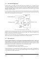
1
Dial-up Audio Interface
Model DAI-2
– INSTALLATION AND OPERATION –
This documentation is valid for
Dial-up Audio Interface hardware version 1.03 with firmware version 2.00
Nashville, Tennessee • 615-228-3500
Table of Contents
Section I – Safety Information
1.1
Safety Information
Page
1.1
Section 2 – FCC Information
2.1
Part 68 Compliance
2.1
Section 3 – Installation
3.1
3.2
3.3
3.4
3.5
3.6
System Includes
Installing the System
Mechanical Installation
DAI-2 Relay Panel Interconnect
Telephone Line Connection
Audio I/O Connection
Logic-Level Input Connections
Manual Connect Input
Control Relay I/O Connections
Power Supply
Telephone Interface
Cellular Telephone with an RJ-11 Adapter
Fixed Location Cellular Telephones
Rural Radiotelephones or Ranch Telephones
Use with RPU Equipment
RF Interference
Lightning Protection Tips
Proper Ground System
Telephone Line Protection
3.1
3.1
3.2
3.2
3.2
3.3
3.3
3.4
3.4
3.4
3.5
3.5
3.5
3.5
3.6
3.6
3.7
3.7
3.7
Section 4 – Operation
4.1
4.2
4.3
4.4
4.5
DAI-2
Overview
Operation from a Remote Telephone
Going Online with the DAI-2
Issuing Commands
Shift Key Commands
Going Offline with the DAI-2
Operaton from a Local Telephone
Connect Button
Manual Connection with Telephone Lines
Manual Connection without Telephone Lines
Operation on a Shared Telephone Line
Transfer from a Dial-up Remote Control
Control via VHF or Microwave RPU
Command Sets
Command Set 0 -- User Defined
Command Set 1 -- Soundbite Recorder
Command Set 2 -- Remote Broadcaster
Command Set 3 -- Emergency Broadcaster
Table of Contents
4.1
4.1
4.1
4.1
4.1
4.1
4.2
4.2
4.2
4.3
4.4
4.4
4.5
4.5
4.5
4.6
4.7
4.8
i
Section 5 – Programming
5.1
5.2
5.3
5.4
5.5
5.6
5.7
Overview
Introduction to the Command Matrix
Programming Mode
Programming Mode Basics
Read from Memory
Write to Memory
Telephone Numbers
Alarm System
Programming Suggestions
Programming Example
Command Matrix
Command Matrix Settings
System Profile Settings
Command Set
Safeguard Timer
Security Codes
Logic-Level Inputs
Telephone Numbers
Automatic Level Control (ALC)
Ring Number
DTMF Hold Time
Identification Tones
Slate Tone
Delay Unit
Leased Line Mode
Memory Address List
Factory Command Matrix Programming
5.1
5.1
5.2
5.2
5.3
5.4
5.4
5.5
5.5
5.6
5.7
5.8
5.9
5.9
5.9
5.9
5.10
5.11
5.11
5.12
5.13
5.13
5.14
5.14
5.14
5.15
5.24
Section 6 – Troubleshooting and Repair
6.1
6.2
6.3
Common Problems and Possible Solutions
Factory Service Policy
Repair Procedure
6.1
6.2
6.3
Section 7 – Specifications
7.1
7.2
7.3
7.4
7.5
DAI-2
Electrical & Mechanical Specifications
Flat Cable Pinout
Schematic Diagrams
Component Layouts
Parts List
Table of Contents
7.1
7.1
7.2
7.3
7.5
ii
Section 1 — Safety Information
!
The DAI-2 Dial-up Audio Interface should be installed only by qualified technical personnel. An attempt to
install this device by a person who is not technically qualified could result in a hazardous condition to the
installer or other personnel, and/or damage to the DAI-2 or other equipment. Please ensure that proper
safety precautions have been made before installing this device.
The DAI-2 Dial-up Audio Interface is registered with the Federal Communications Commission and certified to meet
specific safety requirements. It is extremely important that the DAI-2 not be modified in any way. Modification of this
equipment will void the FCC certification, void the warranty, and perhaps pose a hazard to the user of this equipment
or to maintenance personnel of your local telephone company. Service of the DAI-2 Dial-up Audio Interface should
be performed only by qualified technical personnel who are familiar with the implications of FCC Part 68 registration.
The DAI-2 Dial-up Audio Interface is designed for indoor use in a dry location. Installation and operation in other
locations could be hazardous.
Extreme caution should be used if the DAI-2 Dial-up Audio Interface case is opened without first being
disconnected from the telephone line and the DAI-2/RP Relay Panel. High voltages may be present on
telephone lines, and although the DAI-2 is powered by 12 volts AC from a "wall plug" transformer, failure
of this transformer could cause dangerous and potentially lethal voltages to become present. Only the
supplied transformer should be used.
Depending on the installation, substantial voltages may be connected the DAI-2 relay panel. If this is the case, use
extreme care when working in the vicinity of the DAI-2 and disconnect all sources of high voltage before contacting it.
The DAI-2 contains self-resetting "fuses" that protect it from excessive current.
replacement devices should be of the same type and rating.
If these are replaced, the
The DAI-2, as any electronic device, can fail in unexpected ways and without warning. Do not use the DAI-2 in
applications where a life-threatening condition could result if it were to fail.
DAI-2
Safety Information
page 1. 1
Section 2 — FCC Information
2.1
Part 68 Compliance
The DAI-2 complies with Part 68 of the FCC rules. On the rear panel of the DAI-2 is a label that contains, among other
information, the FCC registration number and ringer equivalence number (REN) for this equipment. If requested, this
information must be provided to the telephone company.
The REN is used to determine the quantity of devices that may be connected to the telephone line. Excessive RENs
on the telephone line may result in devices not ringing in response to an incoming call. In most areas, the sum of the
RENs should not exceed 5.0. Contact the local telephone company to determine the maximum REN for the calling
area.
The DAI-2 is designed for use with standard modular (RJ11C) telephone jacks.
The telephone company may make changes in its facilities, equipment, operations, or procedures that could affect
the operation of the DAI-2. If this happens, the telephone company will provide advance notice in order for you to
make the necessary modifications to maintain uninterrupted service.
If the DAI-2 causes harm to the telephone network, the telephone company will notify you in advance of service
disconnection. But if advance notice isn't practical, the telephone company will notify the customer as soon as
possible. Also, you will be advised of your right to file a complaint with the FCC if you believe it is necessary.
Please contact Sine Systems, Inc., for repair and/or warranty information if you suspect that the DAI-2 has
malfunctioned. If a defective device is causing harm to the telephone network, the telephone company may request
you remove that device from the network until the problem is resolved.
The DAI-2 cannot be used on public coin service lines provided by the telephone company. Connection to Party Line
Service is subject to state tariffs. Contact your state public utility commission, public service commission, or
corporation commission for information.
The DAI-2 is registered with the Federal Communications Commission and is certified to meet specific safety
requirements. It is extremely important that the DAI-2 not be modified in any way. Modification of this equipment will
void the FCC certification, void the warranty, and perhaps pose a hazard to the user of this equipment or to
maintenance personnel of your local telephone company.
Service should be performed only by qualified technical personnel who are familiar with the implications of FCC Part
68 registration. Extreme caution should be used if the DAI-2 case is opened while still connected to the telephone
line. High voltages may be present on telephone lines.
DAI-2
FCC Information
page 2. 1
Section 3 — Installation
!
The DAI-2 Dial-up Audio Interface should be installed only by qualified technical personnel. An attempt to
install this device by a person who is not technically qualified could result in a hazardous condition to the
installer or other personnel, and/or damage to the DAI-2 or other equipment. Broadcast equipment can
operate at voltages that are potentially lethal. Please ensure that proper safety precautions have been
made before installing this device.
3.1
System Includes
The DAI-2 Dial-up Audio Interface package contains these items:
•
•
•
•
•
•
Dial-up Audio Interface model DAI-2
rack mounted chassis and relay panel
ribbon cable with two connectors
12 VDC wall plug supply
modular telephone cable
operation manual
All systems are fully tested before leaving the factory but damage may occur in transport. When the DAI-2 is
unpacked, it should be inspected for obvious signs of mechanical damage or loose parts. Loose parts should be
tightened before installation. If damage is found, save the packing material and report it to the shipping company and
the dealer from which it was purchased. Do not install the system.
3.2
Installing the System
The DAI-2 is easy to install if you are careful, patient and alert. Installation is broken down into a series of logical
steps but you should have some previous engineering experience in a broadcast environment before attempting to
install the DAI-2. Access to the building does not necessarily qualify you as an engineer. We cannot protect you
from yourself, but we want to make this point very clearly: if you are unfamiliar with this type of equipment, please
contact a properly qualified engineer to handle installation and setup of this system.
DAI-2
Installation
page 3. 1
3.2.1
Mechanical Installation
The DAI-2 is designed to be mounted in a standard 19 inch equipment rack. The system generates little heat and can
be mounted in just about any convenient location. The DAI-2 should be mounted at a location which is convenient to
the equipment that will be connected to it.
Figure 3.1; DAI-2 Dial-up Audio Interface
3.2.2
DAI-2 Relay Panel Interconnect
The DAI-2 should be connected to its relay panel with the 20 conductor flat (ribbon) cable. This cable is supplied with
the system and is terminated with one connector at each end. One end of the flat cable connects to the rear of the
DAI-2 control unit at the connector labeled “Relay Panel” (see Figure 3.2). This connector is keyed to fit in one
direction and will be held secure by latches when fully inserted.
Figure 3.2; Rear panel connectors
On the relay panel, the tab on the flat cable connector should line up with the connector outline around J1 on the relay
panel (see Figure 3.3). This connector has no outer shell and is not keyed so make sure that the connector is
properly oriented and aligned with all pins before applying pressure.
3.2.3
Telephone Line Connection
The DAI-2 should be connected to a standard (POTS) telephone line with the modular (RJ11C) jack on the rear panel
labeled "Line". A telephone cable is supplied with the DAI-2 for this purpose.
DAI-2
Installation
page 3. 2
3.2.4
Audio I/O Connections
The DAI-2 has one audio input and one audio output. The audio input feeds audio to the telephone line and the audio
output provides audio from the telephone line. The DAI-2 control circuits allow only one audio port to be active at a
time--the DAI-2 is not a telephone hybrid device. Both the input and output are balanced, high level audio ports.
The audio input and output connections are made through screw terminals on the relay panel. The terminals are
located on a small block to the left of J1 (the relay panel connector) and below the power and logic I/O connections.
Figure 3.3; Relay Panel connects at J1
The DAI-2 audio output can drive a balanced high impedance or 600 ohm load at up to about +4dBm. If the DAI-2
audio output is used to drive an unbalanced load, use either output lead and ground. Do not connect either side of
the DAI-2 audio output to ground for an extended period of time or damage to the DAI-2 could result.
The audio output level of the DAI-2 is adjustable through programming. This is covered in the programming section of
this manual. The DAI-2 is factory programmed to a program level of about +2 to +4 dBm with a slight amount of peak
clipping. Higher output level settings will result in higher output level and more clipping while lower settings will result
in lower output levels and little or no clipping.
The DAI-2 has an internal automatic level control (ALC) that attempts to keep both input and output levels consistent.
The behavior of the ALC is programmable. The ALC can also be enabled or disabled on a key-by-key basis.
The DAI-2 audio input is high impedance (>100K), actively balanced input. It can be driven by either a balanced or
unbalanced source. For unbalanced audio sources, connect the source leads to the IN+ and IN- terminals. It does
not matter which lead is connected to which input. Unlike the audio output, there are no restrictions on grounding the
audio input connections. The DAI-2 is designed to automatically adjust for input levels within the range of -10 dBv to
+4 dBv.
3.2.5
Logic-Level Input Connections
The DAI-2 has four programmable logic-level inputs. All logic-level inputs can be driven by a +5 VDC logic signal, a
contact closure, or a ground referenced open-collector. Logic is active low and internal pull-up resistors are present.
In other words, when using an open-collector or contact closure, a pull down to ground activates the appropriate
function. Logic-level inputs 1 through 4 may be held at ground indefinitely but logic-level input 5 (the manual off-hook
control) should not be held down more than 2.5 seconds.
External logic gates should have the same ground reference as the DAI-2. Unused logic-level inputs should be left
unconnected. The time required for a logic-level input change to activate a function is controlled by userprogramming and is discussed in the programming section of this manual.
The logic-level inputs are labeled LL1-LL4 on the relay panel.
DAI-2
Installation
page 3. 3
3.2.6
Manual Connect Input
There is one single-purpose logic-level input that is used to force the DAI-2 to go off hook. Like the other logic-level
inputs, this one can also be driven by a +5 VDC logic signal, a contact closure, or a ground referenced opencollector. Logic is active low and an internal pull-up resistors is present. The manual connect input is labeled MAN on
the relay panel.
3.2.7
Control Relay I/O Connections
The DAI-2 has eight control relays built in to the relay panel. Seven of these relays are DPDT and one is 4PDT-typically used to switch stereo audio. All contacts, normally-open (NO), normally-closed (NC) and common (COM)
are brought out to screw terminals. The seperate relay poles are denoted A and B (with C and D added where
appropriate).
Figure 3.4; DAI-2 Control relay I/O connections
The relay “control” wiring is pre-wired to the DAI-2 control unit via the flat cable, however, the system is fully
programmable and any combination of relays can be engaged through system programming.
The control relay contacts are rated to withstand 110 VDC at 0.6 A but we do not recommend routing high voltage
through the DAI-2. At 12 VDC the relays can withstand 2.5 A but high current should also be avoided as a matter of
safety with so many exposed terminals. The DAI-2 is designed to switch audio, not power.
Sample wiring diagrams are shown later in this section.
3.2.8
Power Supply
One or both of the DAI-2 GND terminals must be connectiond to the station ground or other qood quality
earth-ground. The DAI-2 contains an internal protection circuit that diverts an abnormally high voltage on
the telephone line to the DAI-2 ground connection. It is very important that the DAI-2 ground connection be
connected to a good quality earth-ground for this protection to work. Failure to do this could result in a
painful or lethal shock to anyone in electrical contact with the DAI-2 if a high voltage were present on the
telephone line from lightning, etc.
DAI-2
Installation
page 3. 4
Power to operate the DAI-2 is supplied by a 12 volt DC wall-plug transformer that is included with the DAI-2. This
transformer is designed for 120 volts AC at 50-60 Hz and is rated at 500 milliamps. The leads of this transformer
should be stripped and tinned and connected to the appropriate screw terminal connectors on the relay panel. The
positive lead (usually denoted by a white stripe) connects to the +12V terminal and the negative lead connects to
GND on the relay panel. (See figure 3.2) Power supply polarity should be verified before the connections are made to
avoid damage to the DAI-2.
3.3
Telephone Interface
The RFC-1 is designed to be connected to an ordinary (POTS) telephone line. In some cases a telephone line is
either not available or is prohibitively expensive. There are several alternatives to a regular telephone line that are
compatible with the RFC-1.
3.3.1
Cellular Telephone with an RJ-11 Adapter
It is possible to connect a cellular telephone to the DAI-2 in place of a telephone line. Some cell phone manufacturers
offer devices that provide a cellular telephone with a standard RJ-11 jack. These devices emulate a standard
telephone line including dial tone, ring voltage and battery. Additionally, the cell phone will usually need to be
outfitted with an external antenna and a constant power supply. Several manufacturers offer these items as part of
their product line but product lines change rapidly. The best approach is to discuss your needs with your supplier to
find a solution that will work.
Most of these RJ-11 adapters generate a square-wave ring signal on an incoming call instead of the sine-wave ring
voltage that is found on a normal telephone line. The DAI-2 has a firmware adjustment that will enable it to recognize
the non-standard ring signal. The Programming section of the DAI-2 documentation provides details on making this
adjustment.
3.3.2
Fixed Location Cellular Telephones
An alternative to using a mobile cell phone with an RJ-11 adapter is to use a cell phone designed specifically for fixed
locations. These phones usually include an RJ-11 connector for outboard equipment and provide a cleaner solution
than the adapter approach. They also tend to be more expensive but they include some items that are extra in the
mobile cell phone approach. Telular, Inc. is a manufacturer of fixed location cell phones. They can be reached at
(800) 229-2326 or http://www.telular.com.
3.3.3
Rural Radiotelephones or Ranch Telephones
Rural radiotelephone systems, or "ranch phones”, are systems that use a full duplex VHF or UHF radio circuit to
extend a telephone line. Two small transceivers are used in this system. One end is connected to a regular
telephone line, the other end has an RJ-11 jack that emulates a regular telephone line. Rural telephones have a
range of roughly 1 to 10 miles depending on terrain. The transmitter power levels are usually in the range of 1 to 10
watts. Because they contain transmitters, rural telephones must be licensed. Channels are scarce in the more
populated areas of the country but are usually available in the areas where rural telephones are most often needed.
Rural radiotelephones usually cost several thousand dollars for a typical system but there is no recurring cost for
service once installed. DX Radio Systems is a provider of radiotelephones. They can be reached at (800) 447-6937
or http://www.tpl-dxrs.com.
DAI-2
Installation
page 3. 5
3.4
Use with RPU Equipment
It is quite feasible to use the DAI-2 with communications links other than telephone lines. For example, the control
and switching capabilities of the DAI-2 often can be useful during remotes using a UHF Remote Pickup Unit (RPU).
The audio output of the RPU receiver should be adjusted to a level between -30 dBm and 0 dBm and then fed to the
LINE jack on the DAI-2. Bring the DAI-2 online the the manual connect control--either from the front panel
pushbutton or the logic-level input.
It is easy to construct an extremely versatile system that allows two communications links to be used with the DAI-2.
Either a telephone line or the output of the RPU receiver can be connected to the DAI-2 using the squelch relay in an
RPU receiver to control a DPDT relay as shown in Figure 3.5.
Figure 3.5; Using both and RPU and telephone line with the DAI-2
The DAI-2 contains an internal 4.5 kHz low-pass filter. This will not limit the bandwidth of audio coming from the
telephone line but it will restrict bandwidth of the audio coming from the RPU. This is usually not a problem for voice
broadcasts, but it may be an issue for music broadcasts.
DTMF tones are used to control the DAI-2 when using a telephone line. DTMF tones can be generated by simple tonedialers but these devices may require modification to obtain the necessary audio connection.
3.5
RF Interference
The DAI-2 is typically a studio device so there have been few reported RF problems with this device. However, since
it can be installed at a transmitter site, a few suggestions on preventing RF interference are in order. The DAI-2 is
designed with bypass caps and suitable RF protection on the telephone line for most installations. However, extreme
conditions exist that require additional external filtering to obtain reliable operation. Extreme conditions are rare but
these problems can be overcome by a combination of one or more of the following remedies:
•
•
Install an RF filter before the "Line" jack near the DAI-2
Loop the ribbon cable several times through a ferrite core at each end
Telephone line RF filters can be obtained through a wholesale distributor or telephone products. Suttle Apparatus is
one manufacturer of these devices. They can be reached at (800) 852-8662 or http://www.suttleonline.com. Be sure
to get an RF filter and not simply a spike protector.
DAI-2
Installation
page 3. 6
3.6
Lightning Protection Tips
!
Damage to the DAI-2 by lightning is not covered under warranty. See the complete warranty for more
information.
In most installations the DAI-2 is connected to both a telephone line and other broadcast equipment. Any equipment
in this situation is subject to severe abuse from lightning. In some installations this happens frequently. Lightning
can enter through the phone line, mistreat the DAI-2 and exit to the station ground system. It can also hit the tower,
elevate the entire ground system above ground by several kilovolts and exit through DAI-2 to ground. This is called a
"ground surge." In other words, the telephone line can hit the DAI-2 or the DAI-2 can hit the telephone line. The same
thing can happen with the power line.
3.6.1
Proper Ground System
The first step in any protection scheme is to install and maintain a high quality ground system. This will serve two
purposes. First, the intensity of the ground surge will be lowered because of the lower resistance to earth ground and
second, if everything is tied together with low impedance conductors, all equipment will stay closer to the same
electrical potential when the system ground takes a hit. All protection devices, equipment racks and transmitters
should be tied together with low impedance conductors, preferably copper strap, as short and as free from bends as
possible. Do not depend on metal conduit for ground connections. A properly designed and installed ground system
will pay for itself many times over in the damage it prevents.
3.6.2
Telephone Line Protection
Be sure your local telephone company has installed gas surge arrestors on your incoming telephone lines. Old
installations may contain carbon protectors which tend to provide less reliable protection. Be sure the ground
connection used by the telephone company is an integral part of your station ground system. Sometimes the
telephone company will use a nearby cold water pipe, metal conduit, or isolated ground rod for their ground and this
may be, electrically speaking, quite a distance from your station ground system. Do not disconnect their ground
connection, just add a supplemental conductor from their ground point to the station ground.
We highly recommend that you purchase and install your own telephone line surge protector in addition to the one
installed by the telephone company. Place this between the incoming telephone line and the DAI-2. These spike
protectors are designed to pick up a ground connection through the ground prong on a standard AC outlet so be sure
this is in fact connected to your station ground by the shortest possible means. For best result, install a "dummy" AC
outlet with no AC connections but with a short jumper from the ground terminal on the outlet the metal rack in which
the DAI-2 relay panel is mounted. Most protectors have internal, non-replaceable fuses which will blow during a
heavy surge. If this happens, replace the protector. Do not attempt to repair it.
DAI-2
Installation
page 3. 7
3.7
Relay Panel Wiring Diagrams
3.7.1
Soundbite Recorder
DAI-2
Installation
page 3. 8
3.7.2
DAI-2
Remote Broadcaster
Installation
page 3. 9
3.7.3
DAI-2
Emergency Broadcaster
Installation
page 3. 10
Section 4 — Operation
4.1
Overview
Since the DAI-2 is controlled by DTMF tones, operating the unit always begins by calling the number where it is
located. The DAI-2 must be connected through a telephone line, even when bench testing, because (normally) the
unit does not normally provide the necessary operating voltage to the telephone. No special phone line or equipment
is required but the controlling telephone must be able to produce DTMF tones. These are the tones generated by the
buttons on a TouchTone® telephone.
The DAI-2 responds to DTMF according to user adjustable programming. Every key on the telephone keypad except
the ❊ key can be programmed to change the state of the output relays or to change the audio switching in the DAI-2.
The ❊ key is used as a function key to change system programming, etc.
4.2
Operation from a Remote Telephone
4.2.1
Going Online with the DAI-2
The DAI-2 will answer the line after two rings (under factory programming) and signal that it has seized the line with
one long tone. Enter the main security code using the telephone keypad. The main security code is factory
programmed to "12345678". After the security code is correctly entered the DAI-2 responds with two short tones. If
the security code is entered incorrectly, the unit will drop the line immediately.
4.2.2
Issuing Commands
The DAI-2 is controlled using one and two digit commands from the keypad of a telephone. The digit keys 0-9 and the
# key cause the unit to perform actions as programmed in user programming with the press of a single key. How the
DAI-2 responds to key presses is determined by a table stored in memory. You indicate how you want the DAI-2 to
respond to each available key by placing specific values in the table. This table effectively forms the command set
for the DAI-2. Command sets are discussed later in this section.
4.2.3
Shift Key Commands
In the DAI-2, the ❊ key acts as a shift key which, in conjunction with a second key, causes the unit to perform a
specific pre-programmed action. These actions are controlled by the DAI-2 and are not programmable by the user.
Shift Key
DAI Function
❊7
❊8
❊99
❊0
❊❊
❊#, 1-6
Enter programming read mode
Enter programming write mode
Hang up
Read firmware version
Shift/Unshift (shift key acts like a toggle)
Reserved for future use
4.2.4
Going Offline with the DAI-2
To end a session with the DAI-2 simply hang up the telephone at any time. The DAI-2 should hang up automatically.
To force the DAI-2 to hang up, press ❊ 99 (two nines). The unit will respond with a series of ten short warning tones
and, at the end of these tones, it will drop the line. Pressing any key while the unit is sending the warning tones will
terminate the hang up sequence and keep the unit in operating mode.
DAI-2
Operation
page 4. 1
4.3
Operation from a Local Telephone
While this is not the normal method of operation, it is possible to connect to the DAI-2 from a local telephone located
near the DAI-2. A local connection is typically used only for initial programming or testing. A local connection
bypasses the security codes. This can be particularly helpful if you change one or more codes are forget them.
4.3.1
Connect Button
The following procedure uses the Connect button located on the rear panel of the DAI-2. This button works as either
a momentary or maintained contact depending on how you use it. If the button is pressed briefly and released, the
DAI-2 will connect to the telephone line and wait for a non-alterable attention signal of ❊❊❊❊ . After the attention
signal is given, the unit will enter the operating mode and remain there until you hang up the telephone.
Figure 4.1; Rear panel (location of Connect button)
If the button is pressed and held, the DAI-2 will wait for the attention signal and enter the operating mode as above. It
will remain in the operating mode as long as the Manual Connect button is held. The connection will be broken when
the button is released for three seconds.
The Manual Connect button is disabled when the DAI-2 is online with a telephone call.
When a connection is made using the Connect button, the DAI-2 does not enforce the programming security code for
10 seconds. This should give you enough time to enter the programming mode in the event that you need to
reprogram any security codes that have been lost. If the DAI-2 is still in operating mode after 10 seconds, it will
enforce the programming security code as usual.
4.3.2
Manual Connection with Telephone Lines
The easiest way to establish a manual connection to the DAI-2 is to use two telephone lines. Designate one line as
the calling line and the other as the receiving line. Connect the DAI-2 to the receiving line and call it from the calling
line. Press the Connect button when you hear the line ringing. This will force the DAI-2 to seize the line and place it in
the operating mode as if the security codes were successfully entered. The DAI-2 will confirm that it is in the
operating mode with two short tones to signal that it is waiting for commands.
It is important to press the button before the DAI-2 answers the line. If the DAI-2 answers first, you will hear one long
tone instead of two short beeps. The long tone indicates that the DAI-2 is expecting a security code.
Operate the unit as you would normally, making any changes you need to the system programming. When you are
finished, hang up the originating telephone. The DAI-2 will hang up automatically.
If you have only one telephone line but you have a cellular telephone, substitute the cell phone for the calling line and
call the DAI-2 as described previously.
DAI-2
Operation
page 4. 2
4.3.3
Manual Connection without Telephone Lines
!
This procedure requires that the cover of the DAI-2 be removed. While the voltages inside the unit should
not exceed about 12-15 VDC, even low voltages can be potentially lethal under certain conditions. This
procedure should only be performed by qualified technical personnel.
The procedure requires you to handle the DAI-2 circuit board. This board contains components that are
sensitive to static electricity. Use proper precautions when handling the circuit board.
This procedure places a 12 VDC voltage source on the modular connector J1 to power a telephone set
directly. It is important that the DAI-2 not be connected to a telephone line with the jumpers in this
position.
This method is similar to the one described in section 4.3.2 except that it does not require any telephone lines or a
cellular phone. The only hardware necessary is a telephone with a standard modular plug and two shorting jumpers or
clip leads.
•
Unplug the supply transformer from the wall outlet and disconnect the telephone line and ribbon
cable connectors from the DAI-2 before starting this procedure.
•
Remove the rear panel of the DAI-2 case by removing the two securing screws. Carefully slide the
circuit board out of the case and place it, component side up, on a non-metallic surface.
•
Arrange three jumpers as shown in Figure 4.2 to enable the telephone voltage. If you do not have
the extra jumpers, clip leads may be used but make sure that they do not short any components.
Normal
Operation
Telephone
Voltage
Figure 4.2; Telephone voltage jumpers JP1
•
DAI-2
Connect the telephone to the telephone line jack and carefully attach the ribbon cable so that the
unit has power. The power LED should illuminate.
Operation
page 4. 3
•
Lift the telephone off hook and press (and release) the Connect button. A relay will click and the
DAI-2 will connect to the telephone. Enter the attention code ❊❊❊❊ on the telephone keypad
activate the DAI-2. You will hear two short beeps to confirm that you are connected.
•
Operate the DAI-2 as you would normally, making any changes you need to the system
programming.
•
This step is extremely important! When you are finished, disconnect the ribbon and telephone
cables. Replace the jumper at JP1 to its original position for normal operation as shown in Figure
4.2. Arrows on the circuit board indicate the correct position for the jumper. Failure to install the
jumper properly may cause damage to the DAI-2 or other equipment.
•
Slide the circuit board back into the case, replace the rear panel and secure it with the two screws
removed at the beginning of this procedure.
4.4
Operation on a Shared Telephone Line
The DAI-2 can share a telephone line with other automated equipment. To avoid complications and unexpected
interactions, it is not usually desirable to have more than one device seize the telephone line. However, with proper
planning a functional solution can be reached.
4.4.1
Transfer from a Dial-up Remote Control
In the scenario, the DAI-2 and a dial-up remote control (such as the Sine Systems RFC-1/B) share a telephone line.
Although the DAI-2 is normally installed at the studio, situations do exist where the DAI-2 is installed at a transmitter
site. The remote control will probably be used more often than the DAI-2 so it will be given priority. When it is not the
desired target device, it will be used to pass the call over to the DAI-2.
Make sure that the remote control is programmed to answer the telephone before the DAI-2. The factory default
setting of both the DAI-2 and the RFC-1/B is to answer on the second ring. To eliminate this conflict, program the
DAI-2 to answer on the fourth ring. Details of changing the ring number to answer are given in the programming
section of this manual. When the ring number is adjusted correctly, the remote control should always answer the
line first. Connect the telephone line to both devices.
Figure 4.3; Relay panel connections
On the DAI-2 relay panel there is a screw terminal connection labeled “MAN”. This connection bridges the switch
contacts of the manual “Connect” switch located on the rear panel of the DAI-2. Pulling this contact to ground is
exactly like pressing the switch. Connect the MAN and GND screw terminals to an unused set of normally open relay
contacts on the remote control relay panel (Sine Systems model RP-8). When the appropriate control relay is
activated, the MAN terminal will be pulled to ground. For this example, let’s assume the control relay is the On/Raise
on channel 7 of the RFC-1/B.
DAI-2
Operation
page 4. 4
Make sure that both devices are powered and establish a normal connection to your remote control. Issue the
security codes and commands necessary to select and control channel 7. (In the case of the RFC-1/B, enter 07 to
select channel 7 and enter the control security code 66.) Issue the command to activate the On/Raise control relay
(# on the RFC-1/B). This command will activate the DAI-2 by bridging the Connect switch as described above. Both
devices are now connected to the telephone line--but the DAI-2 is not yet active.
Enter the hangup command to the remote control (99 for the RFC-1/B) so the remote control releases the line. Enter
❊❊❊❊ to activate the DAI-2. When the DAI-2 activates it will not require security code for access.
When the DAI-2 is waiting for a security code it will not recongize a telephone hang-up (if it did, it would release the
line when the remote control drops off). If the remote control hang-up is causing the DAI-2 to release the line,
increase the length of the security code timer. During a transfer, do not enter the DAI-2 activation command ❊❊❊❊
until after the remote control disconnects from the line.
4.4.2
Control via VHF or microwave RPU
A variation of the “Transfer from Remote Control” connection described above can be used to connect to and control
the DAI-2 using an RPU. This connection can be used instead of (or in addition to) a telephone line. Connect the
squelch relay contacts to the MAN and GND screw terminals described in the previous section. When the RPU is
keyed on, the squelch relay closure will bring the DAI-2 online. Enter ❊❊❊❊ to activate the DAI-2. When the DAI-2
activates it will not require security code for access. The squelch relay will hold the DAI-2 online as long as it is
engaged. When the squelch relay releases, the DAI-2 will disconnect.
Audio signals from the RPU must be routed to the input of the DAI-2. A sample schematic is provided in the
Installation section of this manual. The DAI-2 will ignore chatter on the squelch relay as long as contact is not lost
for more than one full second. You must have an external means of generating DTMF tones to control the DAI-2.
4.5
Command Sets
The DAI-2 stores four command sets in its non-volatile memory. A command set defines how the unit will respond
when telephone keys are pressed and when logic level inputs are activated. Three of these command sets are
permanent and cannot be changed--the forth is fully user programmable. While four commands sets are stored in
memory only one command set can be active at a time. The active command set is selected by changing the
programming in system profile at address 358--Active Command Set.
Command sets tell the DAI-2 how to respond when: a key is pressed; a logic level input is detected; or the system is
reset. Each key and logic level input can set different conditions except the ❊ key which used by the system and is
not programmable. System responses can include: opening, closing or momentarily closing relay contacts;
switching audio either into or out of the DAI-2; generating an audible slate tone for cuing; and triggering a series of
telephone calls to warn of an alarm condition.
4.5.1 Command Set 0 -- User Defined
Command set 0 is entirely user programmable. From the factory, command set 0 contains the same settings as
command set 3 for emergency broadcast operation. Instructions for reprogramming are in the next section of this
manual. The three factory programmed command sets provide good examples of the variety of uses and
programming options for the DAI-2.
DAI-2
Operation
page 4. 5
4.5.2 Command Set 1 -- Soundbite Recorder
Command Set 1 is factory programmed to control an open reel or cart recorder as a soundbite recorder. A suggested
connection diagram is given in the Installation section of this manual to operate the DAI-2 with this command set.
Establish a connection to the DAI-2, enter the appropriate security code to access the operating mode. The keypad
functions for this command set are defined as follows:
Stop
Record
Play
Rewind
Fast Forward
7
9
Slate Tone
*
0
#
Blank buttons are not used
Figure 4.4; Keypad assignments for soundbite recorder
Press
DAI-2 Response
1
2
3
4
5
6
7
8
9,0
❊,#
LL1
LL2-4
Record button--record telephone audio to tape
Stop button--stop tape movement and mute all audio
Play button--monitor tape audio
Rewind button--rewind tape with audio monitor
Stop button--same as [2]
Fast Forward--forward tape with audio monitor
not used
Slate tone--send 300 Hz tone burst for audible spot breaks
not used
not used
Logic Level 1--clears activity alert lamp
not used
All functions are triggered by a single key press with the exception of recording. To begin recording, first press play
[3]. The play relay will lock down for two seconds allowing record [1] to be pressed. The keys must be pressed in this
order or the audio will not be switched to the proper mode for recording. Most machines will recognize clear leader as
end of tape. Use it at both the head and tail of the tape to prevent it from winding off the reel.
When the record button [1] is pressed, a constant contact closure is provided that will not clear until LL1 is tripped.
This can be used to activate an alert lamp in the studio that lights when something has been recorded. A momentary
push button connected from LL1 to ground at the studio will clear the activity lamp.
DAI-2
Operation
page 4. 6
4.5.3 Command Set 2 -- Remote Broadcaster
Command Set 2 is factory programmed as a control unit for remote broadcasts. In this configuration the DAI-2 is
used to start cart machines and switch audio while the air personality is at a remote site. A suggested connection
diagram is given in the Installation section of this manual to operate the DAI-2 with this command set.
Establish a connection to the DAI-2, enter the appropriate security code to access the operating mode. The keypad
functions for this command set are defined as follows:
Start Source 2
Start Source 1 1
2
3
Start Source 3
Start Source 4
AUX
1
AUX
Start Aux 2
2
Start Aux 1
Start Aux 3
Blank buttons
are not used
4
AUX
3
Stop All!
8
AIR
*
On AIR
#
Off AIR
(monitor)
Figure 4.5; Keypad assignments for remote broadcaster
Press
DAI-2 Response
1
2
3
4
5
6
7
8
9
0
#
❊
LL1
LL2
LL3
LL4
Start Cart Machine 1
Start Cart Machine 2
Start Cart Machine 3
Start Cart Machine 4
Start Auxiliary Device 1
Start Auxiliary Device 2
Start Auxiliary Device 3
unused
Stop All!--reset cart machines to idle condition
OFF AIR--monitor air signal
ON AIR--send telephone audio on air
unused
ON AIR--send telephone audio on air
Start Auxiliary Device 1
Start Auxiliary Device 2
Start Auxiliary Device 3
All start buttons switch audio into monitor mode. The STOP key resets all start buttons but leaves audio in the
selected mode. The Off-AIR key resets all start buttons and switches audio to the monitor mode. On-AIR is the only
key that makes the telephone audio live.
DAI-2
Operation
page 4. 7
4.5.4 Command Set 3 -- Emergency Broadcast
The following text describes one way of using the DAI-2 to help meet EAS obligations. It is not meant to
suggest that this is the way to install the DAI-2 to be "FCC legal". There are many ways to install the DAI2 as part of an effective EAS system, however, we suggest that you discuss your proposed system with
your communications attorney or the FCC before installing the DAI-2. Personnel using the DAI-2 must
have adequate knowledge of station EAS procedures to use this tool effectively.
Command Set 3 is factory programmed as a control unit for emergency broadcasts. In this configuration the DAI-2 is
used to switch audio and control an external receiver from a remote location. A suggested connection diagram is
given in the Installation section of this manual to operate the DAI-2 with this command set.
Establish a connection to the DAI-2 from a remote telephone and enter the security code. Once in the operating
mode, the keys will function as follows:
MONITOR
AIR
2
Air Audio
Blank buttons
are not used
5
7
8
EAS Receiver Audio
Program Audio
Telephone Audio
Alert Tones
*
Reset EAS
Receiver
Figure 4.6; Key assignments for Emergency Broadcast Operation
Press
DAI-2 Response
1
2
3
4
5
6
7,8
9
0
#
❊
LL1
LL2
LL3-4
Monitor emergency receiver audio--program audio stays on air
unused
Send emergency receiver audio--replace program audio with emergency receiver audio
Monitor air audio--selected source stays on air
unused
Send program audio--replace emergency receiver audio with program audio
unused
Send telephone audio--replace program audio with telephone audio
Reset emergency receiver--to standby after receiving alert tones
Activate alert tones--send alert tones on air
unused
Trigger alarm system--call studios to notify of emergency condition
Activate alert tones--same as [#]
unused
The "MONITOR" keys will send audio from the selected source to the telephone while leaving the air audio source
alone. If the telephone is the air audio source it will be muted when the monitor source changes. The "ON AIR" keys
change the source of the air audio and automatically switch the monitor to air audio.
DAI-2
Operation
page 4. 8
Section 5 — Programming
!
This section is for qualified technical personnel. It contains information that can change most of the
operating characteristics of the DAI-2 system. Improper use of this information can cause incorrect
readings, erratic behavior or lock remote users out of the system. We strongly recommend that you
understand the basic operation of the DAI-2 and the specifics of the installation you are changing before
applying the information in this section.
Information in this section is based on the original factory programming. Portions of this chapter may not be
accurate if changes have already been made to the system.
5.1
Overview
Because the DAI-2 can be used for such a wide variety of applications, there is no single correct way to set up the
system. In fact, there are several ways to program the system for any given task.
Command sets tell the DAI-2 how to respond when a key is pressed or a logic-level input changes. System
responses can include relay switching, audio switching, triggering alarm call, etc. The main programming issue is to
provide a system where all appropriate options are available and in a system that is easy to understand (and can be
programmed with 12 telephone keys).
To solve this problem, the DAI-2 has an area of memory that is arranged as a 16 x 16 table. Each of the 16 rows
represents a key or an input to the DAI-2 and each of the 16 columns represents an event that can happen when the
input occurs. We call this the command matrix (Figure 5.1). Each location in the matrix can store a one-digit
number, command, that enables or disables a response (column) for an even (row). Each location has an address-a number from 000 to 255--so that it can be programmed individually. By programming the appropriate number at a
specific address, you can change how the DAI-2 responds when a key is pressed.
5.2
Introduction to the Command Matrix
To simplify the setup process, the DAI-2 command settings are programmed in the command matrix. The command
matrix is a table with events down the left side and responses across the top. An event will result in the programmed
responses. The numbers in the matrix are used to turn machine responses on and off and, in some cases, the
numbers determine not only if an event will occur but how it will occur.
DAI-2
Programming
page 5. 1
000
0 Key
Read Status 2
On
This
Action
Relay 1
Set to
This
State
1
016
001
1
017
002
0
018
003
0
019
004
3
020
005
1
021
006
2
022
007
0
023
008
009
2
024
0
025
010
1
026
011
1
027
012
0
028
013
0
029
014
0
030
015
0
031
1 Key
Figure 5.1; Command matrix (excerpt)
Any key (or logic-level input) can activate any or all relays. Key 1 and relay 1 are only “connected” if programming
makes it so. Key 1 can control relay 1, or relay 2, or relay 7, or all eight relays if necessary. The same is true for all
other keys and logic level inputs.Every event is independent. Suppose key 1 is programmed to turn a relay on for two
seconds and key 2 is programmed to turn that same relay off. No matter when key 2 is pressed it will turn the relay
off--even if key 1 was pressed less than two seconds ago. However, key 2 can be programmed to leave that relay
alone while controlling other relays eliminating this interaction.
In addition to the keys and logic level inputs, the command matrix includes an action called "Power up". Power up
determines how the relays, etc., will be set when the DAI-2 is powered on or when a call ends and the DAI-2 hangs up.
An empty command matrix and a list of available commands are included in this section. Programming is much easier
if you fill the printed matrix with the values you will program before making programming changes to the DAI-2.
5.3
Programming Mode
If you have done any advanced programming on a Sine Systems RFC-1 Remote Control System, the programming
method of the DAI-2 Dial-up Audio Interface will seem somewhat familiar. In any case, keep in mind that user
programming is not difficult as long as you pay attention to what you are doing. It will take much longer to clear up the
damage of a rushed programming job then to take the time to do it correctly the first time.
Programming mode is used to verify or alter the command set and change other operating characteristics of the DAI2. Read mode allows you to verify system settings but does not allow you to change any settings. Write mode is
used to alter system settings. Write mode is destructive--new settings overwrite old settings.
5.3.1
Programming Mode Basics
Normal operations are suspended in the programming modes. Relay positions, audio mode, etc. will not be affected
by keystrokes when the DAI-2 is in one of the programming modes.
•
•
•
the command to invoke programming read mode is: ❊-7
the command to invoke programming write mode is: ❊-8
the command to exit the programming mode is: ❊-❊
You can press ❊-❊ at any time to exit programming mode. This key combination has no effect in operating mode so if
you are interrupted during programming, it is best to press ❊ -❊ and simply exit programming mode. Pressing other
keys may write data to unknown memory locations and have adverse effects on system functionality.
DAI-2
Programming
page 5. 2
These items are common to both the read and write programming modes:
•
•
•
•
•
in programming mode, the # key acts like an enter key
in programming mode, one long tone is a prompt for you to enter something
in programming mode, two short beeps is an ‘OK’ response
in programming mode, one long low tone means that an error has occurred
the programming security code is: 1266
The DAI-2 will only prompt for the programming security code one time per call. If you exit programming mode and
enter again during the same call, you will hear the confirmation beeps instead of the prompt tone.
5.3.2
Read from Memory
Read mode is used to verify system settings without making changes.
•
•
•
•
invoke the programming read mode by pressing ❊-7
the DAI-2 responds with one long tone to prompt for the programming security code
enter the programming security code: 1266
the DAI-2 responds with two short beeps to confirm that it is in programming read mode
After the programming security code is correctly entered, the DAI-2 waits for an address. The address identifies
what data should be retrieved by where it resides in memory. To determine the address, locate the description of the
data you would like to read in the command matrix or the system profile. Each space in the command matrix has a
three digit number printed along its edge. In the system profile, each item has a three digit number that is the
address. Leading zeros are significant so all three digits of the address are required. The DAI-2 will reply with two
short beeps to acknowledge a valid address.
•
•
•
enter the three digit address for the data you want to read
press # to read the data from that memory address
the DAI-2 responds with a number of short beeps equal to the value stored at the address
The value zero will produce one long tone instead of zero beeps. Pressing a key while the DAI-2 is beeping will
silence it whether it is finished with the reply or not.
The DAI-2 automatically increments the address one location after it reads the data. If you press the # key again, the
DAI-2 will read the data from the next address and so on. It is possible to increment through all addresses this way.
After pressing # to read data:
•
•
•
DAI-2
press # again to read the value at the next consecutive address , or
enter aaato jump to a new address--aaa, or
enter ❊-❊ to exit the programming mode
Programming
page 5. 3
5.3.3
Write to Memory
Write mode is used to change system settings to alter the behavior of the DAI-2. It works just like read mode except
that you supply new data before pressing the enter key #.
•
•
•
•
invoke the programming write mode by pressing ❊-8
the DAI-2 responds with one long tone to prompt for the programming security code
enter the programming security code: 1266
the DAI-2 responds with two short beeps to confirm that it is in programming write mode
After the programming security code is correctly entered, the DAI-2 waits for an address. The address identifies
what data should be retrieved by where it resides in memory. To determine the address, locate the description of the
data you would like to read in the command matrix or the system profile. Each space in the command matrix has a
three digit number printed along its edge. In the system profile, each item has a three digit number that is the
address. Leading zeros are significant so all three digits of the address are required. The DAI-2 will reply with two
short beeps to acknowledge a valid address.
•
•
•
enter the three digit address for the data you want to change
press d# to write the new data value–d–to the memory address
the DAI-2 responds with a number of short beeps equal to the value stored at the address
The value zero will produce one long tone instead of zero beeps. Pressing a key while the DAI-2 is beeping will
silence it whether it is finished with the reply or not.
The DAI-2 automatically increments the address one location after it writes the data. If you enter more data, the DAI2 will write the data to the next address and so on. It is possible to increment through all addresses this way.
After pressing # to write data:
•
•
•
5.3.4
press d# again to write the value–d–at the next consecutive address , or
enter aaa to jump to a new address--aaa, or
enter ❊-❊ to exit the programming mode
Telephone Numbers
Data for the DAI-2 typically consists of the digits 0 through 9. There are cases, such as telephone numbers and
security codes, where a blank space may be necessary. The ❊ key is used as an empty place holder in these cases.
Enter ❊# in programming mode. A ❊ will be read as ten short beeps.
Telephone numbers may also include a two second pause character. This can be programmed using the # key as a
data key. Enter ## in programming mode. The # key will be read back as eleven short beeps.
Suppose you want to program the first telephone number in the DAI-2. Look in the system profile for the description
"Telephone Number A" . You will find that it is programmed at addresses 256-270. Enter the programming write mode
as explained previously in this text. Enter 256 as the starting address. To program the telephone number 228-3500,
press 2# 2# 8# 3# 5# 0# 0# ❊# ❊# ❊# ❊# ❊# ❊# ❊# ❊#. The number can be up to 15 digits long but only seven are
used in this example. The stars after the final zero are unused digits in the telephone number.
Suppose you need the DAI-2 to dial number using a telephone system that requires a prefix 9 to reach an outgoing
line. Enter the programming mode as above but enter the telephone number as 9# ## 2# 2# 8# 3# 5# 0# 0# ❊# ❊# ❊#
❊# ❊# ❊#. The # after the 9 causes a two second pause when dialing so that the system can access the line.
DAI-2
Programming
page 5. 4
5.3.5
Alarm System
The DAI-2 alarm system monitors the status of the logic-level inputs. When an alarm input appears at one of the
logic-level inputs, the DAI-2 will call the telephone numbers stored in its memory to report the condition. The
telephone numbers will be dialed in rotation starting with the Telephone Number A, then B, C, D, A, B, etc. until the
alarm is cleared or the programmed number of attempts has been made. Program only as many telephone numbers
as needed--blank numbers will be skipped during the dialing sequence.
When it places a call, the DAI-2 will send its identification tones repeatedly as an alert message. This is factory set
to three short beeps. The tones will be sent for the duration of the call unless a user clears the alarm. Press the ❊
key to clear the alarm. The DAI-2 will respond with one long tone as a prompt to enter the security code. Enter the
security code to go online with the DAI-2. Perform whatever actions are necessary in response to the alarm.
There are three mandatory steps to setting up the DAI-2 alarm system:
•
•
•
program the telephone numbers that will be called when the alarm occurs--starting at address 256
enable the alarm system by programming the value 1 at address 355
enable a logic level input by programming a 1 at its control address--starting at address 332
Since alarms are recognized by the DAI-2 on its logic-level inputs, at least one of the logic level inputs must be
enabled in the system profile.
These parameters can be changed to vary how the the DAI-2 alarm system works:
•
•
•
•
•
5.3.6
the time that the alarm input must be present before the alarm is triggered--starting at address 333
the length of the alarm call and the pause between calls at address 340 and 341
the number of call attempts per telephone number at address 342
the site identification tones at address 351
the speed of the tones at address 352
Programming Suggestions
Any unused actions in the command matrix should be programmed so that they do not interfere with actions that are
desirable. Relays should be programmed with the value 2 on unused inputs so that they will not change state. The
audio switcher should be programmed with value 1 for no change.
The alarm system should only be triggered by logic-level inputs. The matrix has spaces for keys and power up to trip
alarms but this is a side effect of using the matrix for programming--these conditions are not valid.
False relay changes can occasionally occur when program audio is feeding through the DAI-2. Occasionally, but
rarely, the audio will mimic a DTMF tone and be detected as such by the internal controller. If you experience this
problem, try increasing the minimum DTMF length at address 349. This setting changes how long DTMF tones must
be present before they are recognized. Keep in mind that this will also increase the length of time that the keys on
the telephone must be held when controlling the DAI-2.
DAI-2
Programming
page 5. 5
5.3.7
Programming Example
000
0 Key
1
016
001
002
1
017
003
0
018
0
019
004
3
020
005
006
1
021
007
2
022
008
0
023
009
2
024
0
025
010
0
026
011
012
0
027
013
0
028
0
029
014
0
030
Reserved
Reserved
Reserved
Read Status
2
Read Status
1
Alarm call
Slate tone
Audio
Relay 8
Relay 7
Relay 6
Relay 5
Relay 4
Relay 3
On
This
Action
Relay 2
Set to
This
State
Relay 1
We can use an sample from the command matrix to illustrate how this system works. Suppose the data for the 0 key
is programmed like this:
015
0
031
1 Key
Figure 5.2; Sample key programming
Using this data, when the 0 key is pressed, the DAI-2 will:
•
•
•
•
•
•
•
•
switch relays 1, 2 and 6 on
switch relays 3, 4 and 8 off
relay 6 will be switched on momentarily
relay 7 will be left alone
switch the audio monitor so that the program audio feed is sent to the telephone line
not generate a slate tone
not make any alarm calls
not read the status of any logic-level inputs
A complete listing of available settings and descriptions is included in this section along with a complete command
matrix. Some conditions appear in the command matrix that do not make sense. For instance, do not alarm calls with
a key press–trigger alarm calls only with a logic-level input. When the dialing sequence starts, it is likely that you will
be disconnected from the DAI-2 if alarm calls are triggered by a key press.
Plan your settings carefully before you begin the process of programming. Watch for cases where two key presses
will have conflicting results on a relay. Remember that audio and relays can be left alone on certain key presses by
programming "no change" conditions.
Suppose you want to change the command matrix so that relay 3 switches on when the 0 key is pressed.
•
•
•
•
•
•
•
•
•
invoke the programming write mode by pressing ❊-8
the DAI-2 responds with one long tone to prompt for the programming security code
enter the programming security code: 1266
the DAI-2 responds with two short beeps to confirm that it is in programming write mode
enter the three digit address for the data you want to change: 002
enter the new data value for this address: 1
press # to write the new data to the address
the DAI-2 responds with one short beep confirming that it wrote a 1
enter ❊-❊ to exit the programming mode
The address 002 came from the command matrix at the point where the 0 key and relay 3 meet. The command value
to turn the relay on (1) is given in a chart later in this section.
DAI-2
Programming
page 5. 6
5.4
Command Matrix
Reserved
Reserved
Reserved
Status 2
Status 1
Alarm Call
Audio
Relay 8
Relay 7
Relay 6
Relay 5
Relay 4
Relay 3
Relay 2
Input
Event
Relay 1
DAI
Response
Slate Tone
Command programming consists of placing numbers that represent actions at specific locations in the memory of the
DAI-2. It is best represented as a matrix with the possible commands listed down the side and the actions performed
across the top.
000
001
002
003
004
005
006
007
008
009
010
011
012
013
014
015
016
017
018
019
020
021
022
023
024
025
026
027
028
029
030
031
032
033
034
035
036
037
038
039
040
041
042
043
044
045
046
047
048
049
050
051
052
053
054
055
056
057
058
059
060
061
062
063
064
065
066
067
068
069
070
071
072
073
074
075
076
077
078
079
080
081
082
083
084
085
086
087
088
089
090
091
092
093
094
095
096
097
098
099
100
101
102
103
104
105
106
107
108
109
110
111
112
113
114
115
116
117
118
119
120
121
122
123
124
125
126
127
128
129
130
131
132
133
134
135
136
137
138
139
140
141
142
143
144
145
146
147
148
149
150
151
152
153
154
155
156
157
158
159
160
161
162
163
164
165
166
167
168
169
170
171
172
173
174
175
176
177
178
179
180
181
182
183
184
185
186
187
188
189
190
191
192
193
194
195
196
197
198
199
200
201
202
203
204
205
206
207
208
209
210
211
212
213
214
215
216
217
218
219
220
221
222
223
224
225
226
227
228
229
230
231
232
233
234
235
236
237
238
239
240
241
242
243
244
245
246
247
248
249
250
251
252
253
254
255
0 Key
1 Key
2 Key
3 Key
4 Key
5 Key
6 Key
7 Key
8 Key
9 Key
# Key
Logic 1
Logic 2
Logic 3
Logic 4
Power Up
Figure 5.3; Command matrix
Every location in the matrix has a unique address denoted by the small three digit number in the upper left corner. To
use the matrix, find the location where the input event (key press) and the response (relay, etc.) meet. Make a note
of the address.
The lists on the following page contain the valid data (commands) for each type of response. Use the list that
corresponds to the feature that you are changing. In that list, locate the appropriate setting. Each setting is
represented by a number in the column of the list labeled ‘Value’.
Using the programming mode, program the value you selected from the list at the address you read from the matrix.
DAI-2
Programming
page 5. 7
5.4.1
Command Matrix Settings
The following list defines the sets of numbers and the actions they represent. Use these values to program the
command matrix.
Value
0
1
2
3
4
5
6
7
+
Value
0
1
2
3
4
5
+
Value
0
1
...
8
9
Value
0
1
+
Value
0
1
+
DAI-2
Relay Action
Turn relay off
Turn relay on
No change
Turn relay on for 1/2 second
Turn relay on for 1 second
Turn relay on for 1 1/2 seconds
Turn relay on for 2 seconds
Turn relay for 2 1/2 seconds
Values over 7 default to 2
Audio Action
Off--mute audio in and out
No change
Monitor audio from inputs / ALC active
Send audio to outputs / ALC active--telephone sends audio
Send audio to outputs/ ALC frozen--telephone sends audio
Send audio to outputs / ALC inactive--programmable fixed gain
Values over 5 default to 1
Slate Action
Off--no tone
Shortest tone
(factory setting 4)
Longer tone
Longest tone
Alarm Action
Off--do not trip alarm
On--trip alarm
Values over 1 default to 0
Read Status Action
Off--do not report status of input
On--report state of input
Values of 2 or more default to 1
Programming
page 5. 8
5.5 System Profile Settings
The following commands are used in the System Profile listing at the end of this section.
5.5.1
Command Set
A command set defines how the DAI-2 will respond to DTMF tones during operation. The DAI-2 stores four command
sets in memory but only one is active at a time. The active command set is programmed at address 358.
Value
0
1
2
3
+
5.5.2
Active Command Set
User Programmable Command Set (factory setting)
Pre-programmed Set 1--Soundbite Recorder
Pre-programmed Set 2--Remote Broadcast
Pre-programmed Set 3--Emergency Operation
Values of 4 or more default to 3
Safeguard Timer
The DAI-2 has a safeguard timer to keep the DAI-2 from staying on-line at a remote location indefinitely. If the unit is
on-line and has not received a key or logic level command for the programmed length of time, it will hang up the line
and reset to power up conditions. The timer can be disabled by programming a value of 10. The safeguard timer is
programmed at address 357.
Value
0
1
2
3
4
5
6
7
8
9
10
5.5.3
Time Out Length
5 minutes
8 minutes
17 minutes
32 minutes
53 minutes
1 hour, 20 minutes (factory setting)
1 hour, 53 minutes
2 hours, 32 minutes
3 hours, 17 minutes
4 hours, 8 minutes
Disabled
Security Codes
There are two programmable security codes in the DAI-2. Each can be up to eight digits in length. Unused digits
should be programmed to 10 using the "*" key to program a 10. The Main Security Code is used to gain access to the
system and is requested any time the unit answers the phone. It is factory programmed as "12345678" at address
316 through 323. The Programming Security Code is requested when there is an attempt to enter the programming
mode of the DAI-2. It is factory programmed to "1266"--the final four digits are 10's so they are ignored--at addresses
324 through 331. While this is not generally recommended, a security code can be entirely disabled by programming
all digits to 10.
Value
Security Code
0-9
10
Required digit in security code
Unused digit in security code
DAI-2
Programming
page 5. 9
When the DAI-2 asks for a security code, a security code timer starts running. If this timer runs out before the code
is given (correctly), the DAI-2 terminates the call. The time set here applies to all security code requests. The length
of time that the user is allowed to give the code is programmable at address 359.
Value
0
1
...
8
9
Security Code Timer
10 seconds
20 seconds--(factory setting)
[(2 to 7) +1] x 10 seconds
90 seconds
100 seconds
The DAI-2 allows 20 seconds for a response when it requests a security code. If the code is not given or given
incorrectly, the unit drops the phone line and, as an added measure of security, does not answer another call for an
adjustable length of time. This time is programmed at address 350.
Value
0
1
...
8
9
5.5.4
Incorrect Security Code Lockout Time
10 seconds
20 seconds
[(2 to 7) +1] x 10 seconds--(factory setting 3)
90 seconds
100 seconds
Logic-Level Inputs
The DAI-2 has four independent logic level inputs to monitor the state of external devices. For each logic level input
used, two items must be programmed. First, the input terminal must be enabled so that the monitoring system will
acknowledge it. And second, the length that the input condition must be present before the system responds must
be set. These are programmed in pairs from address 332 through 339.
Value
0
1
+
Value
0
1
2
3
4
5
6
7
8
9
DAI-2
Logic Level Input
Input Disabled
Input Enabled (factory setting)
Values of 2 or more default to 1
Input Hold Length
0.1 seconds (factory setting)
0.2 seconds
0.9 seconds
2.8 seconds
6.5 seconds
12.6 seconds
21.7 seconds
34.4 seconds
51.3 seconds
73.0 seconds
Programming
page 5. 10
5.5.5
Telephone Numbers
The DAI-2 is capable of dialing up to four telephone numbers of 15 digits each when an alarm condition is detected.
These numbers are programmed from address 256 through 315. The DAI-2 will dial the numbers, in rotation, up to four
times each or until the alarm condition is cleared by user input. It sends the identification tones as its alarm message
during the call. The DAI-2 then pauses between calls in case station personnel are trying to call it. The length of a
call and the length of a pause between calls are programmed at address 340 and 341 respectively. The number of
call attempts is programmed at address 342. The alarm system may be enabled or disabled at any time through
programming at address 355.
Value
0
1
...
8
9
Telephone Call Length and Pause Length
10 seconds
20 seconds
[(2 to 7) +1] x 10 seconds--(factory setting 6)
90 seconds
100 seconds
Value
Telephone Call Attempts
0-1
2
3
4
+
1 Attempt per Telephone Number
2 Attempts per Telephone Number
3 Attempts per Telephone Number (factory setting)
4 Attempts per Telephone Number
Values of 5 or more default to 4
Value
Alarm System
0
1
+
5.5.6
Off--disabled (factory setting)
On--enabled
Values of 2 or more default to 1
Automatic Level Control (ALC)
The DAI-2 does limited audio processing through an internal Automatic Level Control (ALC). The ALC is always
active when the DAI-2 is feeding audio to the telephone line to keep audio within legal tolerances. When audio comes
from the telephone line to the DAI-2, the ALC can be frozen at a specific gain setting or disabled through programming
in the Command Matrix. The ALC characteristics are user programmable starting at address 343.
Value
0
1
...
8
9
Value
0
1
...
8
9
DAI-2
ALC Input and Output Release Speed
Fastest release
Faster release
(factory setting 4)
Slower release
Slowest release
ALC Output Level and Fixed Gain
Lowest level
Lower level
(factory setting 5)
Higher level
Highest level
Programming
page 5. 11
5.5.7
Ring Number
In cases where the DAI-2 shares a telephone line with other equipment it may be necessary to delay answering the
line for a certain number of rings. Program the ring number to answer at address 347.
Value
Ring Number to Answer
0-1
2
...
9
10
Answer on first ring
Answer on second ring (factory setting)
Answer (3-8) rings
Answer on ninth ring
Answer on tenth ring
The DAI-2 may need higher ring sensitivity if it is used with a UHF radio telephone (sometimes called a "ranch
phone"), a cellular-to-RJ11 adapter, or another device which generates a square wave ring signal. However, in
installations where there is a significant amount of "hum" on the telephone line, the ring sensitivity may need to be
lowered. This prevents the DAI-2 from interpreting the hum as a continuous ring. Ring sensitivity is programmed at
address 348.
When ring sensitivity is 0 the DAI-2 does not answer the telephone.
Value
0
1
2
...
8
9
+
Ring Sensitivity
Does not answer
Least sensitive
Less sensitive
(factory setting 5)
More sensitive
Most sensitive
Values above 9 default to 9
The DAI-2 normally detects when a telephone connection is cut off prematurely--before the hang-up command has
been given. This may occur if the telephone line “goes dead” or the operator hangs up the calling phone by accident.
While the pulse hang-up detection can be disabled by programming at address 360, it is recommended that you
carefully consider the possible consequences before changing this programming.
Value
0
1
+
DAI-2
Pulse hang-up detection
Enabled--system will drop line automatically
Disabled--system will remain on-line if connection is dropped
Values above 1 default to 1
Programming
page 5. 12
5.5.8
DTMF Hold Time
The DAI-2 is controlled by the DTMF tones produced by a TouchTone® type telephone. It is normal for audio passing
through the system to occasionally contain sound at the same frequencies as these tones. To reduce the chance of
reacting to these false tones, the DAI-2 is programmed to ignore any tone until it has been present for a set length of
time. DTMF hold time is programmed at address 349.
Value
0
1
2
3
4
5
6
7
8
9
5.5.9
Minimum DTMF hold time
60 ms
70 ms
120 ms--about 1/10 second (factory setting)
150 ms
220 ms--about 1/4 second
310 ms
420 ms
550 ms--about 1/2 second
700 ms--about 3/4 second
870 ms
Identification Tones
When the DAI-2 places a telephone call to signal an alarm condition, it sends a series of short tones to identify itself.
It will repeat these tones until the alarm is cleared or the programmed call length is reached. It may be necessary in
cases where more than one DAI-2 is used to distinguish between the units when they call. Simply program a different
value at address 351 to send a different number of identification tones.
Value
Tones Generated
0-1
2
...
8
9
+
1 tone
2 tones
(3-7) tones (factory setting 3)
8 tones
9 tones
Values above 9 default to 9
The DAI-2 responds to user input through a series of short tones representing numbers. The speed of these tones
can be increased or decreased to suit different users. The tone speed is programmed at address 352.
Value
0
1
...
8
9
DAI-2
Tone Speed
Fastest
Faster
(factory setting 4)
Slower
Slowest
Programming
page 5. 13
5.5.10 Slate Tone
The DAI-2 can produce an audible slate tone that can be used to signal a break between spots when using the
Soundbite Recorder. To use the slate tone, it must be programmed onto one of the keys in the command matrix. (In
the case of the Soundbite Recorder it is pre-programmed in the matrix to key 8.) This tone is adjustable in length by
programming at address 353.
Value
0
1
...
8
9
Slate Action
Shortest tone
Shorter tone
(factory setting 4)
Longer tone
Longest tone
A cue tone can be generated by the DAI-2 when it is being used to send audio. If the cue tone is enabled, the DAI-2
will send a single tone to indicate that the audio mode has switched and the telephone is sending audio. This will
occur any time the audio mode is set to 3 or above. The tone can be used as an "ON AIR" or "RECORDING" cue. It is
automatically muted from the DAI-2 audio output. The cue tone enable is programmed at address 354.
Value
0
1
+
Cue Tone
Off--disabled (factory setting)
On--enabled
Values of 2 or more default to 1
5.5.11 Delay Unit
The DAI-2 can be used with an optional delay unit called the the DB-1. This delay unit is used to mute the 40 ms of
DTMF tone that pass through the unit each time a key is pressed. When the DB-1 is installed, the DAI-2 should be
programmed to recognize it. However, this programming can be used to bypass the Delay Board without removing
the hardware. The Delay Board enable is programmed at address 356.
Value
0
1
+
Delay Board
Not installed--disabled
Installed--enabled (factory setting)
Values of 2 or more default to 1
5.5.12 Leased Line Mode
In some installations it is desirable to have the DAI-2 active all of the time. To accommodate this, the DAI-2 can be
used in leased line mode. In this mode, the DAI-2 is online and active whenever it has power. The DAI-2 cannot be
dialed into when operating this mode. The leased line enable is programmed at address 361.
Value
0
1
DAI-2
Delay Board
Dialup mode (factory setting)
Leased line mode
Programming
page 5. 14
5.6
Memory Address List
This is a list of all available memory address in the DAI-2. The command matrix occupies the first 256 memory
locations from 000-255. System profile parameters start at address 256.
Address
Description
Factory Setting
User Setting
000
001
002
003
004
005
006
007
008
009
010
011
012
013
014
015
(Factory Programming--Reset Emergency Receiver)
0 Key, Relay 1
0 Key, Relay 2
0 Key, Relay 3
0 Key, Relay 4
0 Key, Relay 5
0 Key, Relay 6
0 Key, Relay 7
0 Key, Relay 8
0 Key, Audio
0 Key, Slate tone
0 Key, Alarm call
0 Key, Read Status 1
0 Key, Read Status 2
0 Key, Reserved
0 Key, Reserved
0 Key, Reserved
0
0
0
0
3
0
0
0
2
0
0
0
0
0
0
0
_____
_____
_____
_____
_____
_____
_____
_____
_____
_____
_____
_____
_____
_____
_____
_____
016
017
018
019
020
021
022
023
024
025
026
027
028
029
030
031
(Factory Programming--Monitor Emergency Receiver Audio)
1 Key, Relay 1
1 Key, Relay 2
1 Key, Relay 3
1 Key, Relay 4
1 Key, Relay 5
1 Key, Relay 6
1 Key, Relay 7
1 Key, Relay 8
1 Key, Audio
1 Key, Slate tone
1 Key, Alarm call
1 Key, Read Status 1
1 Key, Read Status 2
1 Key, Reserved
1 Key, Reserved
1 Key, Reserved
2
2
2
1
0
0
0
0
2
0
0
0
0
0
0
0
_____
_____
_____
_____
_____
_____
_____
_____
_____
_____
_____
_____
_____
_____
_____
_____
DAI-2
Programming
page 5. 15
032
033
034
035
036
037
038
039
040
041
042
043
044
045
046
047
(Factory Programming--Unused key)
2 Key, Relay 1
2 Key, Relay 2
2 Key, Relay 3
2 Key, Relay 4
2 Key, Relay 5
2 Key, Relay 6
2 Key, Relay 7
2 Key, Relay 8
2 Key, Audio
2 Key, Slate tone
2 Key, Alarm call
2 Key, Read Status 1
2 Key, Read Status 2
2 Key, Reserved
2 Key, Reserved
2 Key, Reserved
2
2
2
2
2
2
2
2
1
0
0
0
0
0
0
0
_____
_____
_____
_____
_____
_____
_____
_____
_____
_____
_____
_____
_____
_____
_____
_____
048
049
050
051
052
053
054
055
056
057
058
059
060
061
062
063
(Factory Programming--Emergency Receiver Audio on Air)
3 Key, Relay 1
3 Key, Relay 2
3 Key, Relay 3
3 Key, Relay 4
3 Key, Relay 5
3 Key, Relay 6
3 Key, Relay 7
3 Key, Relay 8
3 Key, Audio
3 Key, Slate tone
3 Key, Alarm call
3 Key, Read Status 1
3 Key, Read Status 2
3 Key, Reserved
3 Key, Reserved
3 Key, Reserved
1
1
0
0
0
0
0
0
2
0
0
0
0
0
0
0
_____
_____
_____
_____
_____
_____
_____
_____
_____
_____
_____
_____
_____
_____
_____
_____
064
065
066
067
068
069
070
071
072
073
074
075
076
077
078
079
(Factory Programming--Monitor Air Audio)
4 Key, Relay 1
4 Key, Relay 2
4 Key, Relay 3
4 Key, Relay 4
4 Key, Relay 5
4 Key, Relay 6
4 Key, Relay 7
4 Key, Relay 8
4 Key, Audio
4 Key, Slate tone
4 Key, Alarm call
4 Key, Read Status 1
4 Key, Read Status 2
4 Key, Reserved
4 Key, Reserved
4 Key, Reserved
2
2
2
0
0
0
0
0
2
0
0
0
0
0
0
0
_____
_____
_____
_____
_____
_____
_____
_____
_____
_____
_____
_____
_____
_____
_____
_____
DAI-2
Programming
page 5. 16
080
081
082
083
084
085
086
087
088
089
090
091
092
093
094
095
(Factory Programming--Unused key)
5 Key, Relay 1
5 Key, Relay 2
5 Key, Relay 3
5 Key, Relay 4
5 Key, Relay 5
5 Key, Relay 6
5 Key, Relay 7
5 Key, Relay 8
5 Key, Audio
5 Key, Slate tone
5 Key, Alarm call
5 Key, Read Status 1
5 Key, Read Status 2
5 Key, Reserved
5 Key, Reserved
5 Key, Reserved
2
2
2
2
2
2
2
2
1
0
0
0
0
0
0
0
_____
_____
_____
_____
_____
_____
_____
_____
_____
_____
_____
_____
_____
_____
_____
_____
096
097
098
099
100
101
102
103
104
105
106
107
108
109
110
111
(Factory Programming--Program Audio on Air)
6 Key, Relay 1
6 Key, Relay 2
6 Key, Relay 3
6 Key, Relay 4
6 Key, Relay 5
6 Key, Relay 6
6 Key, Relay 7
6 Key, Relay 8
6 Key, Audio
6 Key, Slate tone
6 Key, Alarm call
6 Key, Read Status 1
6 Key, Read Status 2
6 Key, Reserved
6 Key, Reserved
6 Key, Reserved
0
0
0
0
0
0
0
0
2
0
0
0
0
0
0
0
_____
_____
_____
_____
_____
_____
_____
_____
_____
_____
_____
_____
_____
_____
_____
_____
112
113
114
115
116
117
118
119
120
121
122
123
124
125
126
127
(Factory Programming--Unused key)
7 Key, Relay 1
7 Key, Relay 2
7 Key, Relay 3
7 Key, Relay 4
7 Key, Relay 5
7 Key, Relay 6
7 Key, Relay 7
7 Key, Relay 8
7 Key, Audio
7 Key, Slate tone
7 Key, Alarm call
7 Key, Read Status 1
7 Key, Read Status 2
7 Key, Reserved
7 Key, Reserved
7 Key, Reserved
2
2
2
2
2
2
2
2
1
0
0
0
0
0
0
0
_____
_____
_____
_____
_____
_____
_____
_____
_____
_____
_____
_____
_____
_____
_____
_____
DAI-2
Programming
page 5. 17
128
129
130
131
132
133
134
135
136
137
138
139
140
141
142
143
(Factory Programming--Unused key)
8 Key, Relay 1
8 Key, Relay 2
8 Key, Relay 3
8 Key, Relay 4
8 Key, Relay 5
8 Key, Relay 6
8 Key, Relay 7
8 Key, Relay 8
8 Key, Audio
8 Key, Slate tone
8 Key, Alarm call
8 Key, Read Status 1
8 Key, Read Status 2
8 Key, Reserved
8 Key, Reserved
8 Key, Reserved
2
2
2
2
2
2
2
2
1
0
0
0
0
0
0
0
_____
_____
_____
_____
_____
_____
_____
_____
_____
_____
_____
_____
_____
_____
_____
_____
144
145
146
147
148
149
150
151
152
153
154
155
156
157
158
159
(Factory Programming--Telephone Audio on Air)
9 Key, Relay 1
9 Key, Relay 2
9 Key, Relay 3
9 Key, Relay 4
9 Key, Relay 5
9 Key, Relay 6
9 Key, Relay 7
9 Key, Relay 8
9 Key, Audio
9 Key, Slate tone
9 Key, Alarm call
9 Key, Read Status 1
9 Key, Read Status 2
9 Key, Reserved
9 Key, Reserved
9 Key, Reserved
1
0
0
0
0
0
0
0
3
0
0
0
0
0
0
0
_____
_____
_____
_____
_____
_____
_____
_____
_____
_____
_____
_____
_____
_____
_____
_____
160
161
162
163
164
165
166
167
168
169
170
171
172
173
174
175
(Factory Programming--Alert Tones on Air)
# Key, Relay 1
# Key, Relay 2
# Key, Relay 3
# Key, Relay 4
# Key, Relay 5
# Key, Relay 6
# Key, Relay 7
# Key, Relay 8
# Key, Audio
# Key, Slate tone
# Key, Alarm call
# Key, Read Status 1
# Key, Read Status 2
# Key, Reserved
# Key, Reserved
# Key, Reserved
1
1
1
0
0
3
0
0
2
0
0
0
0
0
0
0
_____
_____
_____
_____
_____
_____
_____
_____
_____
_____
_____
_____
_____
_____
_____
_____
DAI-2
Programming
page 5. 18
176
177
178
179
180
181
182
183
184
185
186
187
188
189
190
191
(Factory Programming--Trigger Alarm System)
Logic Level In 1, Relay 1
Logic Level In 1, Relay 2
Logic Level In 1, Relay 3
Logic Level In 1, Relay 4
Logic Level In 1, Relay 5
Logic Level In 1, Relay 6
Logic Level In 1, Relay 7
Logic Level In 1, Relay 8
Logic Level In 1, Audio
Logic Level In 1, Slate tone
Logic Level In 1, Alarm call
Logic Level In 1, Read Status 1
Logic Level In 1, Read Status 2
Logic Level In 1, Reserved
Logic Level In 1, Reserved
Logic Level In 1, Reserved
2
2
1
0
0
0
0
0
2
0
1
0
0
0
0
0
_____
_____
_____
_____
_____
_____
_____
_____
_____
_____
_____
_____
_____
_____
_____
_____
192
193
194
195
196
197
198
199
200
201
202
203
204
205
206
207
(Factory Programming--Alert Tones on Air)
Logic Level In 2, Relay 1
Logic Level In 2, Relay 2
Logic Level In 2, Relay 3
Logic Level In 2, Relay 4
Logic Level In 2, Relay 5
Logic Level In 2, Relay 6
Logic Level In 2, Relay 7
Logic Level In 2, Relay 8
Logic Level In 2, Audio
Logic Level In 2, Slate tone
Logic Level In 2, Alarm call
Logic Level In 2, Read Status 1
Logic Level In 2, Read Status 2
Logic Level In 2, Reserved
Logic Level In 2, Reserved
Logic Level In 2, Reserved
1
1
0
0
0
0
0
0
2
0
0
0
0
0
0
0
_____
_____
_____
_____
_____
_____
_____
_____
_____
_____
_____
_____
_____
_____
_____
_____
208
209
210
211
212
213
214
215
216
217
218
219
220
221
222
223
(Factory Programming--Unused key)
Logic Level In 3, Relay 1
Logic Level In 3, Relay 2
Logic Level In 3, Relay 3
Logic Level In 3, Relay 4
Logic Level In 3, Relay 5
Logic Level In 3, Relay 6
Logic Level In 3, Relay 7
Logic Level In 3, Relay 8
Logic Level In 3, Audio
Logic Level In 3, Slate tone
Logic Level In 3, Alarm call
Logic Level In 3, Read Status 1
Logic Level In 3, Read Status 2
Logic Level In 3, Reserved
Logic Level In 3, Reserved
Logic Level In 3, Reserved
2
2
2
2
2
2
2
2
1
0
0
0
0
0
0
0
_____
_____
_____
_____
_____
_____
_____
_____
_____
_____
_____
_____
_____
_____
_____
_____
DAI-2
Programming
page 5. 19
224
225
226
227
228
229
230
231
232
233
234
235
236
237
238
239
(Factory Programming--Unused key)
Logic Level In 4, Relay 1
Logic Level In 4, Relay 2
Logic Level In 4, Relay 3
Logic Level In 4, Relay 4
Logic Level In 4, Relay 5
Logic Level In 4, Relay 6
Logic Level In 4, Relay 7
Logic Level In 4, Relay 8
Logic Level In 4, Audio
Logic Level In 4, Slate tone
Logic Level In 4, Alarm call
Logic Level In 4, Read Status 1
Logic Level In 4, Read Status 2
Logic Level In 4, Reserved
Logic Level In 4, Reserved
Logic Level In 4, Reserved
2
2
2
2
2
2
2
2
1
0
0
0
0
0
0
0
_____
_____
_____
_____
_____
_____
_____
_____
_____
_____
_____
_____
_____
_____
_____
_____
240
241
242
243
244
245
246
247
248
249
250
251
252
253
254
255
(Factory Programming--Program Audio on Air)
Power Up, Relay 1
Power Up, Relay 2
Power Up, Relay 3
Power Up, Relay 4
Power Up, Relay 5
Power Up, Relay 6
Power Up, Relay 7
Power Up, Relay 8
Power Up, Audio
Power Up, Slate tone
Power Up, Alarm call
Power Up, Read Status 1
Power Up, Read Status 2
Power Up, Reserved
Power Up, Reserved
Power Up, Reserved
0
0
0
0
0
0
0
0
2
0
0
0
0
0
0
0
_____
_____
_____
_____
_____
_____
_____
_____
_____
_____
_____
_____
_____
_____
_____
_____
DAI-2
Programming
page 5. 20
Address
Description
Paragraph
Factory Setting
User Setting
256
257
258
259
260
261
262
263
264
265
266
267
268
269
270
A Telephone Number; Digit 1
A Telephone Number; Digit 2
A Telephone Number; Digit 3
A Telephone Number; Digit 4
A Telephone Number; Digit 5
A Telephone Number; Digit 6
A Telephone Number; Digit 7
A Telephone Number; Digit 8
A Telephone Number; Digit 9
A Telephone Number; Digit 10
A Telephone Number; Digit 11
A Telephone Number; Digit 12
A Telephone Number; Digit 13
A Telephone Number; Digit 14
A Telephone Number; Digit 15
5
5
5
5
5
5
5
5
5
5
5
5
5
5
5
10
10
10
10
10
10
10
10
10
10
10
10
10
10
10
_____
_____
_____
_____
_____
_____
_____
_____
_____
_____
_____
_____
_____
_____
_____
271
272
273
274
275
276
277
278
279
280
281
282
283
284
285
B Telephone Number; Digit 1
B Telephone Number; Digit 2
B Telephone Number; Digit 3
B Telephone Number; Digit 4
B Telephone Number; Digit 5
B Telephone Number; Digit 6
B Telephone Number; Digit 7
B Telephone Number; Digit 8
B Telephone Number; Digit 9
B Telephone Number; Digit 10
B Telephone Number; Digit 11
B Telephone Number; Digit 12
B Telephone Number; Digit 13
B Telephone Number; Digit 14
B Telephone Number; Digit 15
5
5
5
5
5
5
5
5
5
5
5
5
5
5
5
10
10
10
10
10
10
10
10
10
10
10
10
10
10
10
_____
_____
_____
_____
_____
_____
_____
_____
_____
_____
_____
_____
_____
_____
_____
286
287
288
289
290
291
292
293
294
295
296
297
298
299
300
C Telephone Number; Digit 1
C Telephone Number; Digit 2
C Telephone Number; Digit 3
C Telephone Number; Digit 4
C Telephone Number; Digit 5
C Telephone Number; Digit 6
C Telephone Number; Digit 7
C Telephone Number; Digit 8
C Telephone Number; Digit 9
C Telephone Number; Digit 10
C Telephone Number; Digit 11
C Telephone Number; Digit 12
C Telephone Number; Digit 13
C Telephone Number; Digit 14
C Telephone Number; Digit 15
5
5
5
5
5
5
5
5
5
5
5
5
5
5
5
10
10
10
10
10
10
10
10
10
10
10
10
10
10
10
_____
_____
_____
_____
_____
_____
_____
_____
_____
_____
_____
_____
_____
_____
_____
DAI-2
Programming
page 5. 21
Address
Description
Paragraph
Factory Setting
User Setting
301
302
303
304
305
306
307
308
309
310
311
312
313
314
315
D Telephone Number; Digit 1
D Telephone Number; Digit 2
D Telephone Number; Digit 3
D Telephone Number; Digit 4
D Telephone Number; Digit 5
D Telephone Number; Digit 6
D Telephone Number; Digit 7
D Telephone Number; Digit 8
D Telephone Number; Digit 9
D Telephone Number; Digit 10
D Telephone Number; Digit 11
D Telephone Number; Digit 12
D Telephone Number; Digit 13
D Telephone Number; Digit 14
D Telephone Number; Digit 15
5
5
5
5
5
5
5
5
5
5
5
5
5
5
5
10
10
10
10
10
10
10
10
10
10
10
10
10
10
10
_____
_____
_____
_____
_____
_____
_____
_____
_____
_____
_____
_____
_____
_____
_____
316
317
318
319
320
321
322
323
Main Security Code; Digit 1
Main Security Code; Digit 2
Main Security Code; Digit 3
Main Security Code; Digit 4
Main Security Code; Digit 5
Main Security Code; Digit 6
Main Security Code; Digit 7
Main Security Code; Digit 8
3
3
3
3
3
3
3
3
1
2
3
4
5
6
7
8
_____
_____
_____
_____
_____
_____
_____
_____
324
325
326
327
328
329
330
331
Programming Security Code; Digit 1
Programming Security Code; Digit 2
Programming Security Code; Digit 3
Programming Security Code; Digit 4
Programming Security Code; Digit 5
Programming Security Code; Digit 6
Programming Security Code; Digit 7
Programming Security Code; Digit 8
3
3
3
3
3
3
3
3
1
2
6
6
10
10
10
10
_____
_____
_____
_____
_____
_____
_____
_____
332
333
334
335
336
337
338
339
Logic Level Input 1; Enable
Logic Level Input 1; Length
Logic Level Input 2; Enable
Logic Level Input 2; Length
Logic Level Input 3; Enable
Logic Level Input 3; Length
Logic Level Input 4; Enable
Logic Level Input 4; Length
4
4
4
4
4
4
4
4
1
0
1
0
1
0
1
0
_____
_____
_____
_____
_____
_____
_____
_____
340
341
342
Telephone Call Length
Telephone Pause Length
Telephone Call Attempts
5
5
5
3
3
3
_____
_____
_____
343
344
345
346
ALC Output Level
ALC Fixed Output Gain
ALC Output Release Speed
ALC Input Release Speed
6
6
6
6
8
4
5
2
_____
_____
_____
_____
DAI-2
Programming
page 5. 22
Address
Description
Paragraph
Factory Setting
User Setting
347
348
349
Ring Number (to answer)
Ring Sensitivity
Minimum DTMF Length
7
7
8
2
5
2
_____
_____
_____
350
Incorrect Security Code Lockout Time
3
3
_____
351
352
353
Identification Tones
Tone Speed
Slate Tone Length
9
9
10
3
3
4
_____
_____
_____
354
355
356
Cue Tone Enable
Alarm Enable
Delay Enable
10
5
11
1
0
1
_____
_____
_____
357
Safeguard Timer
2
5
_____
358
359
360
361
Active Command Set
Security Code Timer
Pulse Hangup Inhibit
Leased Line Mode
1
3
7
12
3
1
0
0
_____
_____
_____
_____
Note: The column entitled "Paragraph" in the System Profile List above refers to the paragraph that describes this
feature in Section 5.5.
DAI-2
Programming
page 5. 23
0
0
0
Reserved
Status 2
Reserved
Status 1
Alarm Call
Reserved
239
0
0
0
255
254
0
0
0
0
0
0
0
0
238
253
252
251
250
0
0
0
0
0
249
248
247
0
Slate Tone
Audio
1
2
2
246
245
0
Relay 8
Relay 6
Relay 5
Relay 4
Relay 2
Relay 7
2
2
0
0
3
244
243
242
241
0
2
2
2
2
240
Power Up
0
223
222
0
237
236
235
234
233
232
231
207
0
0
0
0
0
0
0
206
221
220
219
218
0
0
0
0
0
1
2
0
191
190
205
204
203
202
217
216
215
2
230
229
228
227
226
225
224
Logic 4
1
2
2
2
0
175
0
0
0
0
0
189
188
187
186
201
200
199
214
213
2
2
2
2
2
2
2
2
1
0
0
174
0
0
159
158
173
172
0
0
0
0
0
0
0
171
170
0
185
184
183
198
197
212
211
210
209
2
2
2
2
2
208
Logic 3
2
196
195
194
193
2
2
2
2
192
Logic 2
0
1
2
0
0
169
168
167
2
182
181
1
2
2
2
0
143
142
157
156
155
154
127
0
0
0
0
0
141
140
139
138
1
153
152
151
166
165
2
180
179
178
177
176
Logic 1
2
2
2
2
2
164
163
162
161
2
2
2
2
2
160
# Key
1
2
0
0
0
0
0
111
126
125
124
0
0
0
0
0
123
122
0
137
136
135
2
150
149
148
147
146
145
144
9 Key
2
2
1
2
0
0
121
120
119
2
134
133
132
2
0
0
2
095
0
110
109
108
107
106
0
0
0
0
079
094
093
092
0
0
0
0
0
091
090
0
105
104
103
118
117
2
2
2
2
2
131
130
129
128
8 Key
2
3
2
2
2
116
115
114
113
2
0
0
0
0
112
7 Key
0
0
0
0
089
088
087
0
102
101
2
0
0
2
0
0
078
077
076
075
074
0
063
062
0
0
0
0
061
060
059
058
0
073
072
071
086
085
0
100
099
098
097
096
6 Key
2
0
0
0
3
084
083
082
081
0
3
0
0
0
080
5 Key
2
0
047
0
0
0
0
0
046
045
044
0
0
0
0
0
043
042
0
057
056
055
0
070
069
068
067
066
065
064
4 Key
2
0
0
0
0
0
041
040
039
0
054
053
052
3
0
0
2
0
031
030
029
028
027
026
0
0
0
015
014
013
012
0
0
0
025
024
023
038
037
0
0
6
0
2
051
050
049
048
3 Key
1
0
0
0
3
036
035
034
033
0
0
2
0
3
032
2 Key
1
011
010
009
008
2
2
022
021
020
019
018
017
016
1 Key
2
2
007
006
005
004
2
2
2
2
003
002
001
000
0 Key
Relay 3
Input
Event
Relay 1
DAI
Response
0
0
0
0
0
0
2
0
0
1
0
0
0
0
0
0
0
0
0
0
0
Reserved
0
239
238
0
0
255
254
0
0
223
0
0
0
0
207
0
222
253
252
0
Reserved
Status 2
0
251
0
Reserved
Status 1
0
250
0
0
0
237
0
191
206
0
221
0
175
0
0
0
236
235
234
249
1
0
0
190
205
0
159
174
0
0
220
219
0
0
204
0
0
0
2
248
0
Alarm Call
Audio
0
247
246
0
Relay 8
3
0
0
233
0
0
143
0
158
189
0
127
0
142
173
0
188
203
0
218
217
2
232
231
230
245
0
Relay 7
Relay 6
0
0
0
0
0
172
0
187
202
201
2
216
215
0
3
0
171
0
186
185
200
0
0
3
229
244
243
0
214
213
1
199
198
0
0
0
0
0
157
0
111
126
0
141
0
095
0
0
0
156
155
170
169
3
184
183
0
1
0
0
110
125
0
079
094
0
0
140
139
0
154
153
168
0
0
0
0
228
227
0
Relay 5
Relay 4
0
0
182
197
3
212
211
242
0
0
0
167
166
0
181
196
3
0
226
241
240
0
0
0
0
1
152
151
150
165
0
180
195
0
210
225
224
Logic 4
0
0
0
2
0
0
124
0
0
063
0
078
109
0
047
0
062
093
0
0
123
0
138
137
136
135
0
122
0
0
108
0
0
077
0
031
046
0
061
092
0
107
106
121
2
0
091
0
0
2
120
3
2
2
149
164
0
179
194
0
209
208
Logic 3
0
163
0
0
193
192
Logic 2
0
0
134
133
0
119
118
0
2
148
147
178
177
176
Logic 1
2
3
0
0
105
104
0
090
089
2
0
0
076
0
030
045
0
0
075
074
0
060
059
0
029
044
0
0
0
2
088
0
103
102
117
0
132
131
162
0
0
0
0
0
073
0
015
014
013
0
028
043
0
058
057
072
0
0
2
0
027
042
041
2
056
087
086
3
101
116
0
2
146
161
160
# Key
0
0
0
085
0
100
115
0
130
145
144
9 Key
0
2
3
0
2
0
071
070
069
084
0
099
114
0
129
128
8 Key
Relay 3
0
0
0
083
0
098
113
112
7 Key
0
0
0
0
026
025
040
0
055
054
053
0
0
0
012
011
010
009
2
024
039
038
0
0
068
067
082
0
097
096
6 Key
3
0
0
037
0
052
051
066
0
0
023
022
021
036
0
0
0
0
0
0
0
008
007
006
005
0
020
035
3
050
081
080
5 Key
0
0
065
064
4 Key
0
019
034
0
049
048
3 Key
Power Up
3
033
032
2 Key
0
018
017
016
1 Key
0
004
003
002
001
000
0 Key
Relay 2
Input
Event
Relay 1
DAI
Response
Slate Tone
Figure 5.4; Factory command set 1--Soundbite Recorder
0
0
Fi gure 5.5; Factory command set 2--Remote Broadcaster
DAI-2
Programming
page 5. 24
0
2
0
Reserved
Status 2
Reserved
Status 1
Alarm Call
Reserved
239
0
0
0
255
254
0
0
0
0
0
0
0
0
238
253
252
251
250
0
0
0
0
0
249
248
247
0
Slate Tone
Audio
1
2
2
246
245
0
Relay 8
Relay 6
Relay 5
Relay 4
Relay 2
Relay 7
2
2
0
0
0
244
243
242
241
0
2
2
2
2
240
Power Up
0
223
222
0
237
236
235
234
233
232
231
207
0
0
0
0
0
0
0
206
221
220
219
218
0
0
0
0
0
1
2
0
191
190
205
204
203
202
217
216
215
2
230
229
228
227
226
225
224
Logic 4
2
0
0
2
0
175
0
0
0
0
1
189
188
187
186
201
200
199
214
213
2
0
0
0
0
2
2
2
2
0
0
174
0
0
159
158
173
172
0
0
0
0
0
0
0
171
170
0
185
184
183
198
197
212
211
210
209
2
0
0
1
1
208
Logic 3
0
196
195
194
193
1
2
2
2
192
Logic 2
0
2
0
0
0
169
168
167
0
182
181
3
0
0
3
0
143
142
157
156
155
154
127
0
0
0
0
0
141
140
139
138
0
153
152
151
166
165
0
180
179
178
177
176
Logic 1
0
0
0
1
1
164
163
162
161
1
0
0
0
1
160
# Key
1
2
0
0
0
0
0
111
126
125
124
0
0
0
0
0
123
122
0
137
136
135
2
150
149
148
147
146
145
144
9 Key
2
2
1
2
0
0
121
120
119
2
134
133
132
2
0
0
2
095
0
110
109
108
107
106
0
0
0
0
079
094
093
092
0
0
0
0
0
091
090
0
105
104
103
118
117
2
2
2
2
2
131
130
129
128
8 Key
0
0
2
2
2
116
115
114
113
2
0
0
0
0
112
7 Key
1
2
0
0
089
088
087
2
102
101
2
0
0
2
0
0
078
077
076
075
074
0
063
062
0
0
0
0
061
060
059
058
0
073
072
071
086
085
2
100
099
098
097
096
6 Key
0
0
2
2
2
084
083
082
081
2
0
2
2
2
080
5 Key
2
0
047
0
0
0
0
0
046
045
044
0
0
0
0
0
043
042
0
057
056
055
0
070
069
068
067
066
065
064
4 Key
0
0
1
2
0
0
041
040
039
2
054
053
052
2
0
0
2
0
031
030
029
028
027
026
0
0
0
015
014
013
012
0
0
0
025
024
023
038
037
2
0
0
1
1
051
050
049
048
3 Key
0
0
2
2
2
036
035
034
033
2
1
2
2
2
032
2 Key
2
011
010
009
008
0
0
022
021
020
019
018
017
016
1 Key
0
3
007
006
005
004
0
0
0
0
003
002
001
000
0 Key
Relay 3
Input
Event
Relay 1
DAI
Response
Reserved
Reserved
Status 2
Reserved
Status 1
Alarm Call
Audio
Relay 8
Relay 7
Relay 6
Relay 5
Relay 4
Relay 2
Relay 3
Input
Event
Relay 1
DAI
Response
Slate Tone
Figure 5.6; Factory command set 3--Emergency Broadcaster
000
001
002
003
004
005
006
007
008
009
010
011
012
013
014
015
016
017
018
019
020
021
022
023
024
025
026
027
028
029
030
031
032
033
034
035
036
037
038
039
040
041
042
043
044
045
046
047
048
049
050
051
052
053
054
055
056
057
058
059
060
061
062
063
064
065
066
067
068
069
070
071
072
073
074
075
076
077
078
079
080
081
082
083
084
085
086
087
088
089
090
091
092
093
094
095
096
097
098
099
100
101
102
103
104
105
106
107
108
109
110
111
112
113
114
115
116
117
118
119
120
121
122
123
124
125
126
127
128
129
130
131
132
133
134
135
136
137
138
139
140
141
142
143
144
145
146
147
148
149
150
151
152
153
154
155
156
157
158
159
160
161
162
163
164
165
166
167
168
169
170
171
172
173
174
175
176
177
178
179
180
181
182
183
184
185
186
187
188
189
190
191
192
193
194
195
196
197
198
199
200
201
202
203
204
205
206
207
208
209
210
211
212
213
214
215
216
217
218
219
220
221
222
223
224
225
226
227
228
229
230
231
232
233
234
235
236
237
238
239
240
241
242
243
244
245
246
247
248
249
250
251
252
253
254
255
0 Key
1 Key
2 Key
3 Key
4 Key
5 Key
6 Key
7 Key
8 Key
9 Key
# Key
Logic 1
Logic 2
Logic 3
Logic 4
Power Up
Figure 5.7; Blank command matrix
DAI-2
Programming
page 5. 25
Section 6 — Troubleshooting and Repair
6.1
Common Problems and Possible Solutions
Problem:
The DAI-2 does not power up.
Solutions:
Check for shorts on the flat (ribbon) cable. There should be 12VDC on pin 5. Check the wall-plug power
supply for 12 VDC.
Problem:
I reprogrammed the command matrix but my changes do not seem to have any effect.
Solutions:
Use the programming read mode to make sure that you have made the changes that you think you
have. If the data is correct, make sure that the user command set has been activated--address 358.
This address is factory programmed with 3. Reprogram it to 0 to activate the user command set.
Problem:
I changed (either) security code and now I can’t remember it. How do I access the system?
Solutions:
Place a call to the DAI-2 while at the rear panel of the DAI-2. When you hear a ring, press the button
labeled ‘Connect’ on the DAI-2. The DAI-2 will answer and the telephone will stop ringing but nothing
else will happen. Enter ❊❊❊❊ to activate the DAI-2. It will beet two short beeps to confirm that you are
online. You now have 10 seconds to enter the programming mode and read the security code. Enter ❊7 to enter programming read mode. The DAI-2 will beep twice to confirm that you have changed modes.
If you need to check the main security code, enter 316. If you need to check the programming security
code, enter 324. Again, the DAI-2 will beep twice. Press the # key. The DAI-2 will beep a number of
times corresponding to the first digit of the security code. Press the # key seven more times to read the
next seven digits--the code is eight digits max. A long single tone represents zero. Ten short tones
represents a blank space. If you read a blank space before reading eight digits, stop. Digits after the
blank space are ignored. Enter ❊-❊ to exit the programming mode.
Problem:
The DAI-2 is switching relays, etc. by itself. It appears to be receiving false DTMF tones but now keys
were pressed.
Solutions:
Either the program audio has DTMF tones in it or the program content has phantom DTMF tones--sounds
that appear exactly like DTMF tones to the detector. (While this is rare, it does happen.) Increase the
DTMF hold time at address 349. This setting controls the amount of time that a tone must be present
before the DAI-2 responds. Keep in mind that this adjustment also effects the amount of time that you
must press the keys on the telephone to control the DAI-2.
Problem:
There is noise (hum) on the telephone line that is interfering with my ability to control the DAI-2.
Solutions:
The DAI-2 contains internal protection against RF energy. Additional protection may be necessary in
installations near a broadcast transmitter. Keep the telephone line as short as possible. Install an RF
filter at the telephone "Line" jack near the DAI-2. Loop the ribbon cable through a ferrite core near the
DAI-2. On newer models the ribbon cable is quite short and this should not be a cause of interference.
DAI-2
Troubleshooting and Repair
page 6. 1
6.2
Factory Service Policy
These policies are effective August 1999 and are subject to change without prior notice.
6.2.1
Factory Warranty
Sine Systems, Inc. guarantees our products to be free from manufacturing defect for a period of one year from the
original date of purchase from Sine Systems, Inc. This warranty covers the parts and labor necessary to repair the
product to factory specifications. This warranty does not cover damage by lightning, normal wear, misuse, neglect,
improper installation, failure to follow instructions, accidents, alterations, unauthorized repair, damage during transit,
fire, flood, tornado, hurricane or acts of God and/or nature.
6.2.2
Factory Return Policy
The factory return policy only applies to equipment purchased directly from Sine Systems, Inc. Equipment
purchased through a third party (dealer) is subject to the return policy of the dealer and arrangements for return or
exchange must be handled through the dealer.
Sine Systems policy on returns and exchanges with the factory is broken down according to the following schedule:
30 days “no questions asked”
During the first thirty days from the date that equipment ships from our factory we will accept it
back for a full refund less shipping charges provided that the equipment is still in new, resellable
condition with no cosmetic damage. This does not constitute an evaluation program. It is for
legitimate purchases only.
less than 60 days, may be returned less 15% restocking fee
Between 31 and 60 days from the time we ship the equipment, we will accept unmodified equipment
back for a refund less shipping charges and 15% of the invoice cost. This is to cover the cost of
restocking the items which must then be sold at a discount as reconditioned instead of new.
no return after 60 days
We will recondition the equipment for you according to our repair rates but we will not accept it for
refund or exchange after 60 days from the initial purchase.
6.2.3
Factory Service Policy
Sine Systems is proud to offer same day repair service on all of our products. When we receive damaged equipment,
we will repair it and ship it back the same day it arrives. Because we offer immediate service, we do not send loaner
equipment. If we cannot immediately repair equipment and return it, we may ship a loaner unit at our discretion.
While we do not require prior authorization on repairs, we suggest that you verify our shipping address before
returning equipment for repair. Sine Systems is not responsible for items lost in transport or delivered to the wrong
address. Emergency service may be made available on weekends or holidays, at our discretion, if arrangements are
made with us in advance.
DAI-2
Troubleshooting and Repair
page 6. 2
6.2.4
Warranty Service
There is no charge for repair service on items covered under warranty. You are responsible for shipping charges to
return damaged equipment to us for repair. Damage due to negligence, lightning or other acts of nature are not
covered under warranty.
6.2.5
Service Rates
For service not covered under warranty we have a flat rate repair fee. Flat rate repairs cover only components that
fail electrically. Mechanical damage will be assessed on a per repair basis. Repair charges typically fall into one of
these categories. Shipping fees are not covered in the repair rate.
Minor programming adjustments or no damage, $50 plus shipping
Sometimes a system works exactly like it is supposed to when we get it or it can be fixed through a
simple adjustment in firmware. We will do our best to identify intermittent hardware problems and
correct them. The fee covers the time it takes our technician to thoroughly inspect and test the
equipment.
Minor repairs are up to $150 plus shipping
Five or fewer defective components are replaced in a minor to moderate repair. This accounts for
most of our repairs. These repairs may cost less depending on the components replaced and the
amount of time required to complete the repair.
Moderate repairs are $250 plus shipping
Six to ten defective components are replaced in a major repair. Again, we may charge less
depending on the components replaced and the amount of time required to complete repairs.
Major repairs cost more than $250 plus shipping
This occurs rarely but it can happen. If the equipment has blown traces and scorch marks from
burned components, it’s a safe bet that it will take several components and quite a bit of bench time
to repair. We assess this type of repair on a per incident basis.
Damaged beyond recognition, assessed on a per case basis
Hopefully you have insurance. In cases where the board is so badly damaged that it is not worth
repairing we may, at our discretion, offer to replace the destroyed circuit board. The options and
costs vary widely in these cases so we will call with options.
All repairs must be billed to a credit card or shipped COD. Specify which you prefer with your request for service. At
your request, we will call with the total amount of the repair (including applicable shipping charges) so that suitable
payment can be arranged before a COD shipment. If you need a COD total, do not forget to include a telephone
number where you can be contacted.
DAI-2
Troubleshooting and Repair
page 6. 3
6.2.6
Instructions for Factory Service
Please include a note with any specific information available about the equipment failure as an aid to our technicians.
Pack equipment carefully to avoid further damage in shipping. We are not responsible for damage during transport.
When returning a system with multiple components, we strongly suggest that you return the entire system. We will
repair the parts that are returned but lightning is rarely selective enough to damage only a single part of a system.
Be sure to include a street address for return shipping by UPS. The repair will be delayed if you neglect to give us
enough information to return your equipment--this actually happens! If you prefer a carrier other than UPS or wish us
to bill to your shipping account, we can usually accommodate these requests. Many carriers do not accept COD
shipments so credit card billing may be required for carriers other than UPS. If you do not specify otherwise, return
shipments will be made by the UPS equivalent of the received shipping method (i.e. Ground shipment, 2nd Day,
Overnight).
We suggest that you verify our shipping address before sending equipment for repair. Same day service does not
apply if you ship to an incorrect address and/or the carrier delivers the equipment too late in the day for repairs to be
completed. Sine Systems is not responsible for equipment that is not delivered to our factory. It will be your
responsibility to contact the carrier to retrieve your improperly delivered equipment.
6.3
Repair Procedure
!
The DAI-2 and its relay panel should be installed or repaired only by qualified technical personnel. An
attempt to repair this device by a person who is not technically qualified could result in a hazardous
condition to the installer or other personnel, and/or damage to the DAI-2 or other equipment. Please
ensure that proper safety precautions have been made before installing or repairing this device.
Because the DAI-2 is an FCC registered device, it must not be modified in any way. Any components
which are replaced must be replaced with ones of exactly the same type and rating. This is particularly
critical in the circuitry involving connection to the telephone line. Unless repair is performed by a
properly qualified technician, it is strongly recommended that the DAI-2 be returned to Sine Systems for
repair.
The first step in troubleshooting should be to look for signs of burned or otherwise damaged parts. U9 may run a little
warm but should not be hot enough to burn or discolor the PC board. Check the incoming DC voltage (12 volts).
Check for +5 volts DC at the output of the regulator (U9). The bottom two resistors in the SIP network R10 form a
voltage divider which generates a midpoint reference voltage for the analog circuits. Check to see that this is onehalf the main power supply voltage. If it is not, something is pulling it up or down. The current consumption of the
DAI-2 at 12 volts DC should be about 80 milliamperes. If it is significantly more than this, remove the ICs one at a
time until the current drops.
DAI-2
Troubleshooting and Repair
page 6. 4
6.3.1
Circuit Description
The heart of the DAI-2 is a Motorola MC68HC711 microcontroller. It contains the CPU, program ROM and RAM,
timers, parallel I/O and an A-D converter. The CD22202 (U7) DTMF decoder, the ULN2803 (U8) octal open-collector
driver, the MAX7624 multiplying converter, and the status inputs connect directly to it. The microprocessor operates
off a 3.579 MHz crystal oscillator and a portion of this signal is used to drive the DTMF decoder as well.
Figure 6.1; DAI-2 block diagram
D5 is a 15 volt, 5 watt zener which protects the DAI-2 from over-voltage and reverse-polarity on the power supply
input. U9 is a standard 5 volt regulator. U-1 is a "low voltage interrupt" (LVI) device which resets the microprocessor
if its supply voltage falls below 4.5 volts.
U5b and U5c comprise the balanced audio output section. U5a serves in the balanced audio input section. U4 is a
multiplying D-A converter which is configured as a programmable gain amplifier (PGA). U5d buffers the output of the
PGA. This drives the level detection circuit and a third order low pass filter using U2c. The DC output of the level
detection circuit is fed to the analog-to-digital (A-D) converter in the microprocessor. U3 is a CMOS switch with four
single-pole-single-throw sections and is used to route audio. U2a and U2d comprise a hybrid circuit that lowers the
amount of "send" audio arriving at the DTMF detector.
OC1 detects ring and hang-up signals. A hang-up is detected by a step voltage change on the telephone line caused
by a momentary "battery" interruption (loop break). Capacitors C2 and C3, and inductors L1 and L2 form a low pass
filter to attenuate radio frequency interference (RFI). SP1 is a three terminal gas surge protector.
DAI-2
Troubleshooting and Repair
page 6. 5
Section 7 — Specifications
7.1
DAI-2 Dial-up Audio Interface
Power
12 Volts AC, 0.25 amps
Ports
Relay Panel (20 conductor pin/plug type)
Line (RJ-11C modular)
Power (screw terminals)
Delay (internal 5 conductor pin/plug type)
Controls
Connect (SPST momentary push button)
Inputs
5 Volt DC logic-level active low (screw terminals)
Outputs
7 SPDT relay contact closures (screw terminals)
1 DPDT relay contact closure (screw terminals)
Audio Input
-10 dBv to +4 dBv active balanced with at least 100KΩ load impedance
Audio Output
-4 dBm to +4 dBm active balanced into 600Ω or greater load
Jumpers
3 position jumper to apply phantom power to telephone
Dimensions
19” (w) x 5.5” (d) x 1.75” (h)
Weight
1.5 lbs.
Interference
Complies with the limits for a Class B computing device pursuant to Subpart J of Part 15 of FCC
Rules
7.2
Flat Cable Pinout
Pin#
Connection
1
2
3
4
5
6
7
8
9
10
DAI-2
audio output (high)
audio output (low)
audio input (high)
audio input (low)
+12 volts DC (power)
ground (and power negative)
ground (and power negative)
open-collector output #1
open-collector output #2
open-collector output #3
Pin#
11
12
13
14
15
16
17
18
19
20
Connection
open-collector output #4
open-collector output #5
open-collector output #6
open-collector output #7
open-collector output #8
logic-level input #1
logic-level input #2
logic-level input #3
logic-level input #4
logic-level input #5 (manual off-hook control)
Specifications
page 7. 1