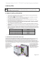
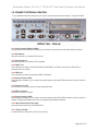
1
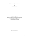
Wonderware TPC
Series B – PentiumM/CeleronM CPU Based
Industrial Touch Panel Computers
10.4”, 12.1”, 15”, & 17”
User Manual
Wonderware Fanless 10.4 & 12.1” TPC & OIC Touch Panel Computers User Manual
Introducing Wonderware Touch Panel Computers – Series B...................................................................3
Trademarks .............................................................................................................................................3
NOTES....................................................................................................................................................4
Symbols used in this Manual....................................................................................................................4
CE-CONFORMITY ..................................................................................................................................5
FCC Class A Radio Frequency ................................................................................................................5
1. INTRODUCTION .................................................................................................................................6
1.1. APPROPRIATE USE................................................................................................................................... 6
1.2 ITEM CHECKLIST........................................................................................................................................ 6
1.3 IMPORTANT SAFETY INSTRUCTIONS ....................................................................................................... 7
All cautions and warnings on the Panel PC should be noted.....................................................................7
2. OVERVIEW .........................................................................................................................................8
2.1 FEATURES:................................................................................................................................................. 8
3. INSTALLATION ...................................................................................................................................9
3.1 PANEL PC INSTALLATION NOTES ............................................................................................................. 9
3.1.1 SEPARATION OF DISPLAY BEZEL AND PC BOX .........................................................................9
3.2 CONNECT EXTERNAL DEVICES .............................................................................................................. 10
3.3 CONNECT INTERNAL DEVICES ............................................................................................................... 12
3.4 INTERNAL JUMPER SETTING .................................................................................................................. 13
3.5 SOFTWARE INSTALLATION ..................................................................................................................... 15
4. MAINTENANCE................................................................................................................................16
4.1 TECHNICAL SUPPORT ............................................................................................................................. 17
4.2 CLEANING ................................................................................................................................................ 17
5. TECHNICAL DETAILS.......................................................................................................................18
5.1 DIMENSIONS ............................................................................................................................................ 18
5.2 POWER – MAIN POWER INPUT................................................................................................................ 18
5.3 ENVIRONMENTAL SPECIFICATION ......................................................................................................... 19
5.4 CONNECTOR PINOUT .............................................................................................................................. 20
5.5 BLOCK DIAGRAM ..................................................................................................................................... 22
6. DISPOSAL.........................................................................................................................................23
7. RETURNING OF DEFECTIVE MERCHANDISE ................................................................................23
Page 2 of 23
Wonderware Fanless 10.4 & 12.1” TPC & OIC Touch Panel Computers User Manual
Introducing Wonderware Touch Panel Computers – Series B
Invensys Systems, Inc. – Wonderware has selected Kontron Panel PCs for Series B of our Touch Panel
Computer line. These Touch Panel computers build on the previous Series A units. The Series B units
are fanless, have higher speed processors, and increased Graphics ability. These Panel PC’s are used
in Wonderware’s hardware-software bundled solutions. When purchasing a Wonderware bundled system
you get a powerful combination of leading software with leading hardware, and you also get one single
source for all related Technical Support.
For Technical Support for Wonderware pre-installed software and/or PanelPC hardware in your
Wonderware bundle, contact your local Wonderware Distributor or Wonderware’s Technical Support. For
more information refer to the “Technical Support” section in this manual.
All rights reserved. No part of this documentation shall be reproduced, stored in a retrieval system, or
transmitted by any means, electronic, mechanical, photocopying, recording, or otherwise, without the prior
written permission of Invensys Systems, Inc. No copyright or patent liability is assumed with respect to the
use of the information contained herein. Although every precaution has been taken in the preparation of
this documentation, the publisher and the author assume no responsibility for errors or omissions.
Neither is any liability assumed for damages resulting from the use of the information contained herein.
The information in this documentation is subject to change without notice and does not represent a
commitment on the part of Invensys Systems, Inc. © 2004 Invensys Systems, Inc. All Rights Reserved.
(With permission from Kontron Embedded Computers GmbH)
Invensys Systems, Inc.
33 Commercial Street
Foxboro, MA 02035
(949) 727-3200
http://www.wonderware.com
Trademarks
All terms mentioned in this book that are known to be trademarks or service marks have been
appropriately capitalized. Invensys Systems, Inc. cannot attest to the accuracy of this information. Use of
a term in this book should not be regarded as affecting the validity of any trademark or service mark.
Kontron, EcoPanel are trademarks of Kontron Embedded Computers GmbH. Alarm Logger,
ActiveFactory, ArchestrA, Avantis, DBDump, DBLoad, DTAnalyst, FactoryFocus, FactoryOffice,
FactorySuite, hotlinks, InBatch, InControl, IndustrialRAD, IndustrialSQL Server, InTouch, InTrack,
MaintenanceSuite, MuniSuite, QI Analyst, SCADAlarm, SCADASuite, SuiteLink, SuiteVoyager,
WindowMaker, WindowViewer, Wonderware, and Wonderware Logger are trademarks of Invensys
Systems, Inc., its subsidiaries and affiliates. All other brands may be trademarks of their respective
owners.
Page 3 of 23
Wonderware Fanless 10.4 & 12.1” TPC & OIC Touch Panel Computers User Manual
NOTES
The information contained in this manual may be subject to technical changes particularly as a result of
continuous product upgrades. The attached documentation does not entail any guarantee on the part of
either Invensys Systems, Inc. or Kontron Embedded Computers with respect to technical processes
described in the manual or any product characteristics set out in the manual. Kontron Embedded
Computers does not accept any liability for any printing errors or other inaccuracies in the manual unless
it can be proven that Kontron Embedded Computers is aware of such errors or inaccuracies or that
Kontron Embedded Computers is unaware of these as a result of gross negligence and Kontron
Embedded Computers has failed to eliminate these errors or inaccuracies for this reason. Invensys
Systems, Inc. and Kontron Embedded Computers expressly inform the user that this manual only
contains a general description of technical processes and instructions which may not be applicable in
every individual case. In cases of doubt, please contact Invensys Systems, Inc.- Wonderware. This
manual is protected by copyright. All rights are reserved by either Invensys Systems, Inc. or Kontron
Embedded Computers. Copies of all or part of this manual or translations into a different language may
only be made with the prior written consent of Invensys Systems, Inc. Invensys Systems, Inc. and
Kontron Embedded Computers point out that the information contained in this manual is continuously
being updated in line with the technical alterations and improvements made by Invensys Systems, Inc.
and Kontron Embedded Computers to the products and thus this manual only reflects the technical status
of the products at the time of printing.
© 2004 by Kontron Embedded Computers
Printing and duplication, even of sections, is only permissible with the express approval of
Invensys Systems, Inc.
33 Commercial Street
Foxboro, MA 02035
(949) 727-3200
http://www.wonderware.com
Symbols used in this Manual
Symbol
Meaning
This symbol indicates the danger of injury to the user or the risk
of damage to the product if the corresponding warning notices are
not observed.
This symbol indicates that the product or parts thereof may be
damaged if the corresponding warning notices are not observed.
This symbol indicates general information about the product and
the user manual.
This symbol indicates detail information about the specific product
configuration.
This symbol precedes helpful hints and tips for daily use.
Page 4 of 23
Wonderware Fanless 10.4 & 12.1” TPC & OIC Touch Panel Computers User Manual
CE-CONFORMITY
The following requirements, standards, specifications constitute part of the declaration:
EN
55022 class A
EN 55024
EN
60950
EN
61000-3-2
EN 61000-3-3 EN
61000-6-2
The validation of this declaration depends on the properly use of the product.
FCC Class A Radio Frequency
This equipment has been tested and found to comply with the limits for a Class A digital device,
pursuant to 1/47 CFR Part 15.109 Class A of FCC rules. Operation is subject to the following two
conditions:
1. This device may not cause harmful interference and
2. This device must accept any interference received, including interference that may cause undesired
operation.
The limits of FCC Part15 class A are designed to provide reasonable protection against harmful
interference in residential installation. This equipment generates, uses, and can radiate radio
frequency energy and, if not installed and used in accordance with the instructions, may cause
harmful interference to radio communications. However, there is no guarantee that interference will
not occur in a particular installation. If this equipment does cause harmful interference to radio or
television reception, which can be determined by turning the equipment off and on, the user is
encouraged to try to correct the interference by more of one or more of the following measures:
1. Reorient or relocate the receiving antenna
2. Increase the separation between the equipment and receiver.
3. Connect the equipment into an outlet on a circuit different from that to which the receiver is
connected
4. Consult the dealer or an experienced radio/television technician for help.
Notice1: The changes or modifications not expressly approved by the party responsible for compliance
could void the user’s authority to operate the equipment.
Notice2: Shielded interface cables, if any, must be used in order to comply with emission limits.
CAUTION!
RISK OF EXPLOSION IF BATTERY IS REPLACED BY AN INCORRECT TYPE
DISPOSE OF USED BATTERIES ACCORDING TO THE INSTRUCTIONS
Page 5 of 23
Wonderware Fanless 10.4 & 12.1” TPC & OIC Touch Panel Computers User Manual
1. INTRODUCTION
Note on the Warranty
Due to their limited service life, parts which, by their nature, are especially subject to wear (wearing parts)
are not included in the guarantee beyond the legal stipulations.
Exclusion of Accident Liability Obligation
Invensys Systems, Inc. - Wonderware and Kontron Embedded Computers shall be exempted from the
statutory accident liability obligation if the user fails to observe the safety instructions.
Liability Limitation / Exemption from the Warranty Obligation
In the event of damage to the device caused by failure to observe the hints in this manual and eventually
on the device (especially the safety instructions), Invensys Systems, Inc shall not be required to honor the
warranty even during the warranty period and shall be exempted from the statutory accident liability
obligation.
1.1. APPROPRIATE USE
The main use of the Panel is with 24VDC power sources according to power supply implemented.
•
•
•
The surrounding area of the rear of the Panel PC should be closed and dry.
The Panel is intended for industrial applications in machine and plant control engineering.
The user is not entitled to change the system or open the body (except for separation of PC
Box and Display Bezel) without consultation to Wonderware.
1.2 ITEM CHECKLIST
Your Panel comes securely packaged in a solid shipping carton. Upon receiving your Panel, open the
carton and carefully remove the contents.
The shipping carton should contain the following items:
- Panel PC - 10.4”, 12.1”, 15”, or 17”
- Drivers and Utilities CD
- Windows XP Installation CD set
- 24V DC Power cord
- CPU / Mother board User Manual
- Wonderware software CD’s (InTouch, Device Integration, Industrial Application Server, etc.)
- Recovery CD or DVD set (once available, for use with external USB drive)
- Mounting cutout template
- Panel stiffeners
- AC to DC converter and AC power cables
Carefully inspect each component to ensure that nothing is missing and/or damaged. If any of these
items is missing or damaged, please contact your Wonderware sales person or Distributor immediately.
Take care of the packing material for future transportation.
Page 6 of 23
Wonderware Fanless 10.4 & 12.1” TPC & OIC Touch Panel Computers User Manual
1.3 IMPORTANT SAFETY INSTRUCTIONS
This section gives you detailed information about how to maintain a safe working environment while
using the Panel PC. You can maintain its condition and performance by following these guidelines.
Please read it carefully to ensure maximum safety.
• Be careful about the power supply input voltage. The Panel PC has specific power
requirements.
•
•
•
•
•
Please protect the Panel PC from humidity.
Never pour any liquid on the PC box section of the Panel PC. This may cause fire or electrical
shock.
Place the Panel PC on a reliable surface when installing. A drop or fall may cause damage.
Do not leave the Panel PC in an unconditional environment. Storage temperature above 60°C
may damage the Panel PC.
The opening on the enclosure are for air convection, protect the Panel PC from overheating.
DO NOT COVER THE OPENINGS on the PANEL PC BOX
•
•
If the Panel PC is not in use for a long time, disconnect it from mains to avoid possible damage by
transient over-voltage.
If you open the housing of the Panel PC for service, all parts of the Panel PC must first be
switched off, after which the Panel PC can be separated from the System. Protect against power
being restored to the Panel PC while it is being serviced.
Following service activities on the Panel could cause failures.
• Metal objects such as screws or tools falling into the Panel PC
• Internal cables being removed or inserted during Panel PC operation.
• Plug-in cards being removed or inserted while the Panel PC power is on.
All cautions and warnings on the Panel PC should be noted.
The system has to shut down and checked immediately by service staff, if one of the following
situations appears:
•
•
•
•
•
•
The power cord or plug is damaged.
Liquid has penetrated into the Panel PC.
The Panel PC has been exposed to moisture.
The Panel PC has dropped and been physically damaged.
The Panel PC has any obvious signs of physical damage.
The Panel PC has not worked well or you can not get it work according to users manual.
Page 7 of 23
Wonderware Fanless 10.4 & 12.1” TPC & OIC Touch Panel Computers User Manual
2. OVERVIEW
The Wonderware Touch Panel Computer is a high performance system. The compact design
enables integration even in very restricted spaces. The Industrial Touch Panel PC meets the highest
requirements for shock, vibration and temperature resistance. The system also provides a high
resistance under tough EMC conditions.
2.1 FEATURES:
-
-
Display sizes 10.4“, 12.1“, 15”, and 17”
Display type TFT active Matrix LCD with resistive touch.
Color depth 32 bit
Resolution: 800 x 600 for 10.4” & 12”, 1024 x 768 for 15”, 1280 x 1024 for 17”
Intel Pentium M Processor 1.1 GHz or Celeron M 600 MHz
512MB RAM (up to 1024 MB on SDRAM)
Standard interfaces 2x USB, 2x PS/2, 1x LPT, 2x LAN, 2x RS232, 1xRS422/485, 1x CRT
(additional USB on Aluminum Bezel units)
Input power of 24 VDC (AC capable with use of external AC/DC power supply)
Installation of two PCI extension cards. (one consumed by HDD)
Front side protection rating - IP65 (conform to EN 60529)
Front in Stainless Steel or Aluminum Bezel with Black coated frame
Operating temperature up to 50°C
Operating system Windows XP Pro (or XP Embedded)
Dimensions:
Panel size Width Height Depth
10.4“
348mm 277mm 112mm
12.1“
380mm 312mm 117mm
15“
449mm 354mm 117mm
17“
461mm 399mm 122mm
All connectors built for industrial use
Shock and vibration tested
Embedded architecture long-life electronic components
Optional on Aluminum Bezel front: 1x USB, Power ON switch, power LED
Page 8 of 23
Wonderware Fanless 10.4 & 12.1” TPC & OIC Touch Panel Computers User Manual
3. INSTALLATION
Attention!
The weight of the range of the Panel PC family is approximately 7 to 14 Kg (15.5 to 31 lbs.).
Use 2 hands to carry it at all times.
3.1 PANEL PC INSTALLATION NOTES
•
•
•
•
•
•
•
The Panel PC is developed to work in a control cabinet. Therefore it must be pointed that the
environmental conditions must be considered.
When installing the Panel PC, take care that there is enough area for ventilations on rear side.
For details on the Panel PC size, go to item housing dimensions.
If you need to boot from other devices, look up for further settings for the BIOS on the single
board manuals provided in the accessory kit.
For the enclosure cutout’s, a template was included in the box the Panel PC came in. If needed,
it can also be downloaded from the Wonderware Tech Support website. Contact Wonderware
Tech Support for more information if needed.
The nuts needed to mount the Panel PC into the enclosure, are already available on the bezel
mounting studs. You need to remove these nuts prior to installing into the enclosure, for a proper
installation.
The use of Panel PC Stiffeners is required if the enclosure housing material is less then 2.5mm
(.098 or 1/10 of an inch). If there were no stiffeners in the box the Panel PC came in then please
contact your Wonderware Sales person or Distributor to obtain the following part number for your
specific Panel PC.
10.4” Panel PC Stiffener part number
99-0044
12.1” Panel PC Stiffener part number
99-0045
15” Panel PC Stiffener part number
99-0046
17” Panel PC Stiffener part number
99-0047
Install any additional PC cards into the Panel PC prior to installation into the enclosure.
3.1.1 SEPARATION OF DISPLAY BEZEL AND PC BOX
In order to aid in the installation of the Panel PC, the Display Bezel and the PC Box can be separated.
This is done by loosening 2 screws, carefully pulling the 2 pieces away from each other, and
disconnecting the 3 cables that are connected to the back of the Display Bezel. Make sure to not pull
the connections apart by the cable, but to grasp the connector its self, and gently wiggle them apart.
When reassembling them, you’ll find that there is only one connector that will fit in a particular receptacle
on the back of the Display Bezel. This way, you will not inadvertently connect to the wrong receptacle.
In the image below,
that need to be
red circle. You will
your panel will rest,
highlighted with yellow
connections are
circle.
you can see the 2 screws
loosened, highlighted with a
see 2 hinge points, where
and swing down from,
circles. Also, the data cable
highlighted with a green
Page 9 of 23
Wonderware Fanless 10.4 & 12.1” TPC & OIC Touch Panel Computers User Manual
3.2 CONNECT EXTERNAL DEVICES
To get detailed information about pin-out of each connector please see the section “Technical details”.
3.2.1 Serial Interface RS422 / RS485
This differential serial interface enables you to connect a external device with 9 pin DSUB connector.
3.2.2 PS/2 Mouse
Use this connector to connect a PS/2 mouse.
3.2.3 PS/2 Keyboard
Use this connector to connect a PS/2 keyboard.
3.2.4 LAN1 Port
This connector provides a external interfaces 10/100 BaseT on RJ45 to connect your Panel PC to
other devices in a network.
3.2.5 USB port
This connector provides two external USB 2.0 interfaces
3.2.6 Serial Interface COM1
Serial interface enables you to connect an external device with 9 pin DSUB connector such as mouse or
modem.
3.2.7 Parallel port LPT
Use this port to connect a printer or other parallel devices.
3.2.8 VGA Connector
Interface to VGA/CRT monitor.
3.2.9 Serial Interface COM2
Serial interface enables you to connect an external device with 9 pin DSUB connector such as mouse or
modem. COM2 is selectable as an input for programming Fieldbus controller.
3.2.10 Hard Disk Drive Activity light
Is on when there is activity on the Hard Drive.
3.2.11 Power On light
Lit when Panel PC has power, and PC is turned on.
Page 10 of 23
Wonderware Fanless 10.4 & 12.1” TPC & OIC Touch Panel Computers User Manual
3.2.12 LAN2 Port
This connector provides a second external interface 10/100 BaseT on RJ45 to connect your Panel PC to
other devices in a network.
3.2.13 Reset
Reset Switch to reset the whole unit.
3.2.14 Main Power IN
Use this connector to connect the power supply of 24VDC. Please note the Power requirements (See
technical details section).
3.2.15 ATX Power ON Switch
This button enables you to switch on and off the main system.
3.2.16 PCI card slots
Allow addition of half sized PCI cards to the system. 2 slots, but one is used on systems with HDD
3.2.17 Front side USB Port (on Aluminum Bezel units)
Use this port behind a the plastic cover to connect USB devices
Page 11 of 23
Wonderware Fanless 10.4 & 12.1” TPC & OIC Touch Panel Computers User Manual
3.3 CONNECT INTERNAL DEVICES
The Panel provides additional functions which could be implemented in the system by adding PCI
cards to the Panel PC.
3.3.1 PCI Extension card
PCI cards are installed just the same as they are on standard PC’s. To access the PCI card slots,
remove the 2 screws (in red circle of image below) and then swing the cover off in the direction of
the red arrows. Make sure to remove the PCI slot cover, and to install the PCI card bracket screw
so that the card stays in place once installed.
3.3.2 CompactFlash memory card
On the top side of the Panel you will find the connector for Compact Flash (CF) card. Loosen the
screw, highlighted in the red square (images below), and then place the CF card into the slot. Pay
close attention that it goes in correctly. Use the ejector button to remove the CF Card
Page 12 of 23
Wonderware Fanless 10.4 & 12.1” TPC & OIC Touch Panel Computers User Manual
3.4 INTERNAL JUMPER SETTING
To identify the jumper location, please look to the section titled ‘Technical Details’. All described
functions refer to the implemented Baseboard.
3.4.1 Backlight supply voltage
Setting
1-2(default)
2-3
3.4.2 Display supply voltage
Setting
1-6 (default)
2-5
3-4
(J5)
Backlight supply voltage
12v
5v
(J16)
Display supply voltage
3v
5v
12v
Page 13 of 23
Wonderware Fanless 10.4 & 12.1” TPC & OIC Touch Panel Computers User Manual
3.4.3 Dip Switch
All switches on this DIP are, and must be, set to “ON”
(SW1)
3.4.4 Master-Slave configuration of CF
(SW2)
Setting SW2 DIP1
OFF(default)
ON
Function of CompactFlash
Master
Slave
3.4.5 I/O configuration of COM 2
(SW2)
Setting SW2 DIP2
OFF(default)
ON
Function of COM2
COM2
No function
3.4.6 Function front power button
(SW2)
Setting SW2 DIP3
OFF
ON(default)
Function of Front side power button
Power button J12 disabled
Power button J12 enabled
3.4.7 Function USB Port 2 (front side)
(SW2)
Setting SW2 DIP4
OFF(default)
ON
Function of Front side USB port
USB Port 2 enabled
USB Port 2 disabled
3.4.8 Main-board connector selection USB Port 0 (backside of PC Box)
Setting SW4 DIP1
OFF(default)
ON
(SW4)
USB Port 0 – connector select
External Connector J22
Internal Connector J31
3.4.9 Main-board connector selection USB Port 1 (backside of PC Box)
Setting SW4 DIP2
OFF(default)
ON
USB Port 1 – connector select
External Connector J22
Internal Connector J31
3.4.10 HDD and Power LED Status Indicators
Description
D16 bottom
D16 top
(SW4)
Display
POWER
HDD
(D16)
Color
Green
Red
Page 14 of 23
Wonderware Fanless 10.4 & 12.1” TPC & OIC Touch Panel Computers User Manual
3.5 SOFTWARE INSTALLATION
3.5.1 Application software and operating system
The Panel is designed to work with different operating systems. Wonderware will deliver the panels
with a pre-installed and configured OS. All drivers are installed, and located under C:\Tools folder.
The current OS being delivered is XP Pro. English is the primary language, but using the
Multilingual User Interface pack that comes with the OS, there is an ability to convert the User
Interface to other languages.
Also pre-installed, is Wonderware InTouch, Industrial Application Server Bootstrap, and some
Ethernet based Wonderware DA Servers.
You will also find that some other products have been pre-installed for your convenience and use. A
PDF viewing utility and My-T-Touch on screen keyboard software for example. These products
come with their own help files, and are supported by their respective creators. Wonderware Tech
Support will assist as a front line support for these products, but may refer you to the product
manufacturer for more difficult issues.
In addition, the Panel PC was also delivered with a software license for the Wonderware products,
pre-installed. You may want to make and keep a backup copy of this file. It will only work on the
Panel PC it was delivered on. In the event you have inadvertently deleted the file, contact your Tech
Support provider for a replacement copy.
Wonderware also provides a Recovery CD set, for use when the system HDD has been replaced, or
has become corrupted. This Recovery CD set allows you to restore the system, with the OS, drivers,
and all installed software setup and ready to go. For details on how to use the Recovery CD set,
please refer to the Tech Notes published on the Wonderware Support website.
The Recovery CD set also includes software product CD’s that can be used to make your own
custom Recovery CD’s, or to create and manage system backup’s.
3.5.2 Hardware drivers
In the event you are not going to use the supplied OS, or for some other reason need to install the
hardware drives, you have some options. They can be first saved from the C:\Tools folder prior to
deletion from the HDD. Also, you can download them from the Wonderware Tech Support website.
If you are not finding the drivers you need, please contact Tech Support.
Page 15 of 23
Wonderware Fanless 10.4 & 12.1” TPC & OIC Touch Panel Computers User Manual
4. MAINTENANCE
The Panel is designed and produced according to DIN EN ISO 9000:2000. One of the main
development intentions was to reduce the amount of service required for the unit. As a result, with the
exception of changing the CMOS battery and general cleaning, there is not much servicing that will need
to be done.
In the event of any problems, please contact your Wonderware Technical Support representative. Make
not of any errors reported, as well as the part number and serial number of the Panel PC that is having
the problem.
You can also make sure that all external hardware connections are made, and that the problem is not the
result of a software configuration change that has been made since delivery of the Panel. You can
always use the Recovery CD set to restore to the original software configuration, but remember to create
a backup of the Wonderware software license file first.
Do not attempt to repair the internal hardware yourself.
No warranty after unqualified intrusion
Page 16 of 23
Wonderware Fanless 10.4 & 12.1” TPC & OIC Touch Panel Computers User Manual
4.1 TECHNICAL SUPPORT
For technical support, please contact Wonderware or your local Wonderware Certified Support Provider.
TEL:
1 (800) WONDER1 (US and Canada) / (949) 639-8500 (Outside North America)
E-mail: [email protected]
Web:
http://www.wonderware.com/Support/MMI/
Make sure you have the following information on hand when you call:
• unit part id number (P/No #) (located on rear of panel)
• unit serial number (S/No #) (located on the rear of panel)
If the problem is related to your pre-installed Wonderware software, be ready to provide the additional
information:
• The version of Wonderware software you are running.
• The version of the operating system you are using. For example, Microsoft Windows XP ProSP1.
• The exact wording of system error messages encountered.
• Any relevant output listing from the Logger, the Microsoft Event Viewer, or any other diagnostic
applications.
• Details of the attempts you made to solve the problem(s) and your results.
• Details on how to recreate the issue.
• If known, the Wonderware Technical Support case number assigned to your issue (if this is an ongoing issue).
4.2 CLEANING
•
To clean the surface of the Panel PC, use a soft lint-free cloth. It should be slightly moist with a
mild detergent solution or any computer cleaning kit.
•
•
•
•
Never use alcohol, petroleum-based solvents or aggressive agents to clean the Panel.
Take care to never poor any liquids directly into the Panel PC Box.
Do not use paper towels to clean the display screen. Paper can scratch the display
touch film.
To clean the liquid-crystal display (LCD) screen use soft clean lint-free cloth, moist with a
mild glass cleaner, and gently wipe the surface. Never apply liquids directly on the screen
surface.
Page 17 of 23
Wonderware Fanless 10.4 & 12.1” TPC & OIC Touch Panel Computers User Manual
5. TECHNICAL DETAILS
5.1 DIMENSIONS
System
A
B
10” Panel 348 277
12” Panel 380 312
15” Panel 449 354
17” Panel 461 399
* All values in mm
C
D
E
F
G
H
I
J
K
102.5
86
270 79.25 295 32.25 6 234 200
175.5 141.5 270 79.25 324
37.5 6 263 200
186.2 138.5 270 79.25 406.4 37.5 6 311 200
180.5 149.5 270 79.25 418
43
6 356 200
L
M4
M4
M4
M4
5.2 POWER – MAIN POWER INPUT
V (In) = 24VDC +/- 20% with protection against reverse polarity.
A (Amps) = 3.6 Max at 24 VDC
Page 18 of 23
Wonderware Fanless 10.4 & 12.1” TPC & OIC Touch Panel Computers User Manual
5.3 ENVIRONMENTAL SPECIFICATION
Temperature ranges:
Operation
Storage
Relative humidity:
5 to +50°C
-20 to +60°C
20 to 80% non-condensing
Page 19 of 23
Wonderware Fanless 10.4 & 12.1” TPC & OIC Touch Panel Computers User Manual
5.4 CONNECTOR PINOUT
5.4.1
PS/2 Keyboard/Mouse Connector
PIN
1
2
3
Keyboard
Signal Name PIN
KBDATA#
4
NC
5
GND
6
5.4.2
LAN + Dual USB Combo Connector
PIN
1
2
3
4
5
6
7
8
LAN
Signal Name
TX+
TXRX+
NC
NC
RXNC
NC
5.4.3
LPT, COM1, COM2, VGA Connector
PIN
1
2
3
4
5
6
7
8
9
10
11
12
13
LPT
Signal Name
STROBE#
DATA0
DATA1
DATA2
DATA3
DATA4
DATA5
DATA6
DATA7
ACK#
BUSY#
PE
SELECT
PIN
A1
A2
A3
A4
Signal Name
VCC
KBCLK#
NC
PIN
7
8
9
USB
Signal Name PIN
VCC
B1
DataB2
Data+
B3
GND
B4
LPT (cont’d)
PIN
Signal Name
14
AFD#
15
ERROR#
16
INIT#
17
SLIN#
18
GND
19
GND
20
GND
21
GND
22
GND
23
GND
24
GND
25
GND
PIN
1
2
3
4
5
6
7
8
9
Mouse
Signal Name PIN
MSDATA#
10
NC
11
GND
12
Signal Name
VCC
MSCLK#
NC
Signal Name
VCC
DataData+
GND
COM
Signal Name
DCD(Data Carrier Detect)
RXD(Receive Data)
TXD(Transmit Data)
DTR(Data Terminal Ready)
GND
DSR(Data Set Ready)
RTS(Request To Send)
CTS(Clear To Send)
RI(Ring Indicator)
PIN
1
2
3
4
5
6
7
8
9
10
11
12
13
14
15
CRT
Signal Name
RED
GREEN
BLUE
NC
CRTGND
CRTGND
CRTGND
CRTGND
VCC
CRTGND
NC
DDCDAT
HSYNC
VSYNC
DDCCLK
Page 20 of 23
Wonderware Fanless 10.4 & 12.1” TPC & OIC Touch Panel Computers User Manual
5.4.4
PIN
1
2
3
4
5
6
7
8
LAN1 Port
Signal Name when 82541ER
loaded 10/100/1000 BaseT
MX_0+
MX_0MX_1+
MX_2+
MX_2MX_1MX_3+
MX_3-
Signal name when 82551xx
loaded 10/100 BaseT
TXD+
TXDRXD+
NC
NC
RXDNC
NC
5.4.5 Power Connector
1
PIN
1
2
3
Signal Name
GND
NC
24VDC in
5.4.5
RS422/485 Connector
PIN
1
2
3
4
5
6
7
8
9
3
RS422/485
Signal Name
TxDRxD+
TxD+
RxDGND
RTSRTS+
CTS+
CTS-
JP1 and JP2 are located on a card that is inside the PC Box, attached to the RS422/485 Connector.
Diagram for exact location of jumpers on that card is below.
Mode
RS422
RS485
JP1
closed
open
JP2
closed
open
Page 21 of 23
Wonderware Fanless 10.4 & 12.1” TPC & OIC Touch Panel Computers User Manual
5.5 BLOCK DIAGRAM
The diagram displayed below is a basic functional block diagram of the Panel PC Main-board
components and functions, and how they are connected.
Page 22 of 23
Wonderware Fanless 10.4 & 12.1” TPC & OIC Touch Panel Computers User Manual
6. DISPOSAL
In order to dispose of your Panel PC, it must be removed from the plant and fully dismantled.
Electronic parts such as disc drives and circuit boards must be disposed of in accordance with
national electronic scrap regulations.
For details ask your local waste disposal department.
7. RETURNING OF DEFECTIVE MERCHANDISE
Before returning any merchandise, please:
1. Contact Wonderware Technical Support and request an RMA number (Return Material Authorization).
2. Describe the device failure behavior or reason for return.
restocking fee.
Any returns for credit are subject to a
3. Upon confirmation of a hardware failure or valid cause for return, Wonderware will provide a Return
Merchandise Authorization (RMA).
4. Make sure to receive an RMA number from Wonderware before returning any merchandise. Clearly
write or mark this number on the outside of the package you are returning. Any returns without an
authorization will be refused and returned to you by the shipper.
5. When returning goods, include the name and telephone number of a person whom we can contact for
further explanations if necessary. Where applicable, always include all duty papers and invoice(s)
associated with the item(s) in question:
•
Ensure that the unit is properly packed in the original box. A product packaging manual will
be included with the replacement Panel or can be emailed to you in advance. Please refer to
it for the necessary instructions on how to appropriately package the panel computer being
returned. Failure to do so may result in the panel shifting during transit –which may result in
physical damage. Physical damage from improper packaging will void your system warranty.
•
Ship the panel back to the address provided on the RMA documentation, via an insured
carrier with freight pre-paid.
•
Return unit must be received to address provided within 30 days, or invoice for full amount of
Panel PC will be issued.
Page 23 of 23