1
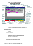
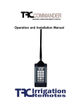
PGM Controller Models PL800, PL1600i PL1600, PL1620, PL1624, PL4800 Owner’s Manual Installation Instructions for each model included separately. www.weathermatic.com Introduction Congratulations! The ProLine™ controller performs timed watering and is ready for options like rain and freeze sensors, SLRC remote control and SmartWire 2-Wire installation (models PL1600i and PL1600 only). ATTENTION INSTALLER: PLEASE READ BEFORE INSTALLING AND SAVE THIS MANUAL FOR SYSTEM OWNER. INSTALLATION INSTRUCTIONS FOR EACH MODEL IS INCLUDED SEPARATELY. This controller is not intended for use by young children or the infirm without supervision. Young children should be supervised to insure they do not play with this appliance. If the supply cord is damaged it must be replaced by the manufacturer, an authorized service agent or a similarly qualified person in order to avoid a hazard. U.S. Patent No. 6,314,340 TRADEMARKS: Weathermatic® ProLine™ Smart Solutions for the Professional® www.weathermatic.com Installation 2.0 www.weathermatic.com 2.0Installation www.weathermatic.com Table of Contents 1.0 ProLine™ Accessories . . . . . . . . . . . . . . . . . . . . . . 1 2.0 Getting Acquainted With Your ProLine™ Controller 2.1 Getting Acquainted With Your ProLine™ Control Panel . . . . . . . . . . . . . . . . . . 2 2.2 Programming . . . . . . . . . . . . . . . . . . . . . . . . . 4 3.0 Programming . . . . . . . . . . . . . . . . . . . . . . . . . . 5 3.1 Current Time/Date . . . . . . . . . . . . . . . . . . . . . 5 3.2 Program Start Times . . . . . . . . . . . . . . . . . . . . 5 3.3 Zone Run Times . . . . . . . . . . . . . . . . . . . . . . . 6 3.4 Days to Water . . . . . . . . . . . . . . . . . . . . . . . . . 7 3.5 Omit Times/Days/Dates . . . . . . . . . . . . . . . . . 7 3.6 Monthly % Adjust . . . . . . . . . . . . . . . . . . . . . . 8 4.0 Manual Start Functions . . . . . . . . . . . . . . . . . . . . 4.1 Manual Zone . . . . . . . . . . . . . . . . . . . . . . . . . 4.2 Manual Test . . . . . . . . . . . . . . . . . . . . . . . . . . 4.3 Manual Program . . . . . . . . . . . . . . . . . . . . . . . 5.0 System Diagnostics and Eco Features . . . . . . . 5.1 Multimeter . . . . . . . . . . . . . . . . . . . . . . . . . . 5.2 Valve Locator . . . . . . . . . . . . . . . . . . . . . . . . 5.3 Sensor Operation . . . . . . . . . . . . . . . . . . . . . 5.4 Run and Soak Cycles . . . . . . . . . . . . . . . . . . . 9 9 9 9 10 10 10 11 11 6.0 Advanced Functions . . . . . . . . . . . . . . . . . . . . . 6.1 FAULT . . . . . . . . . . . . . . . . . . . . . . . . . . . . . 6.2 RAIN DLY . . . . . . . . . . . . . . . . . . . . . . . . . . . 6.3 DS TIME . . . . . . . . . . . . . . . . . . . . . . . . . . . . 6.4 NUM START . . . . . . . . . . . . . . . . . . . . . . . . . 6.5 ZN:ZN DLY . . . . . . . . . . . . . . . . . . . . . . . . . . 6.6 MV:ZN DLY . . . . . . . . . . . . . . . . . . . . . . . . . . 6.7 MV/ZONE . . . . . . . . . . . . . . . . . . . . . . . . . . . 6.8 CLR PGM . . . . . . . . . . . . . . . . . . . . . . . . . . . 6.9 CLR ALL . . . . . . . . . . . . . . . . . . . . . . . . . . . . 6.10WIRELESS . . . . . . . . . . . . . . . . . . . . . . . . . . . 6.11 ABOUT . . . . . . . . . . . . . . . . . . . . . . . . . . . . . 6.12GROW-IN . . . . . . . . . . . . . . . . . . . . . . . . . . . 6.13DEFAULT . . . . . . . . . . . . . . . . . . . . . . . . . . . 12 13 13 14 14 14 14 15 15 15 15 15 16 16 7.0 Troubleshooting . . . . . . . . . . . . . . . . . . . . . . . . . 7.1 Master Reset Procedure For The ProLine™ Controller . . . . . . . . . . . . . 7.2 Watering Cycle Pause Functions . . . . . . . . . . . 7.3 Troubleshooting Guide . . . . . . . . . . . . . . . . . 16 16 17 18 www.weathermatic.com 1.0 Accessories PGM SELECT MODE ZONE RUN PROGRAM ZONE STATUS R B POWER 1 MASTER VALVE SLM2 2-Zone Module for PL800 only SLM4 4-Zone Module for PL1600 and PL1600i only R 2 B SLM48DM 2-Wire Module R 3 B R B PROGRAM PORT SLM16DM, SLM24DM, SLM48DM SmartWire Decoder Modules for PL1600i and PL1600 only SLM12 12-Zone Module for PL4800 only Sidekick FM Receiver for Weathermatic ® Power On Station On Irrigation Remotes www.irrigationremotes.com 1(800) 275-8558 ™ OFF ON 1 2 4 5 7 8 9 ON 0 OFF 3 6 Irrigation Remotes SLRC-HH Wireless Remote Control SLHUB-RF Wireless Receiver SLRC-KIT-HUB Wireless R/C Kit for All ProLine™ Models 420LS Rain/Freeze Sensor 420GLS Rain Sensor for All ProLine™ Models Sidekick Wireless Remote Control Transmitter (Available through authorized TRC distributors. Contact TRC at 1-800-275-8558 or www.irrigationremotes.com.) ProLine™ accessories available through your professional Weathermatic installer. For the Weathermatic distributor directory, go to www.weathermatic.com. 1 www.weathermatic.com Getting acquainted with your ProLine™® Controller 2.0 2.1 Getting Acquainted With Your ProLine™ Control 2.0 Getting Acquainted With Your ProLine™ Controller Panel PGM SUN A MON TUE WED THU FRI SAT The ProLine™ Controller B C LCD Display provides the D FAULT NO AC following information when the controller is set to RUN, SYSTEM OFF, or when there is no active watering operation underway (display with program in IDLE mode): PGM Time of Day Battery Strength: ProLine™ Controllers use a Real Time Clock/Calendar instead of a backup battery to maintain correct time during a power outage. For the PL1600i, PL1600 and PL4800, the display will show a blank battery icon in the display until/unless a battery is installed in the controller. Battery usage is only necessary for programming when the control panel is removed. Next Watering Day or Days: The display will show the watering days in the current week for Program A. To view watering days for Program B, C or D just press the PGM button. Fault Indicator: Appears ONLY when a fault is detected. Turn dial to Advanced Functions and press NEXT button to view faults. Once you turn the dial to Advanced Functions, the fault indicator will stop flashing but will continue to appear on the screen until the fault is removed or user clears fault in Advanced Functions. If fault is cleared in Advanced Functions, it will appear again the next time the program runs if the problem is not corrected. 2 2.0 Getting acquainted with your ProLine™® Controller No AC: Appears when there is no AC supply to the controller. you press and hold the RUN MANUAL PROGRAM button for 15 seconds, the selected program will operate in a continuous loop. In other words, it will keep running the program continuously until the dial is switched to SYSTEM OFF. PGM Button: The ProLine™ controller has 4 watering programs (A, B, C, and D). This is like having 4 controllers in one. You can assign zones to any program you like or more than one program except that zones assigned to Program D cannot be given a run time in A, B, or C. Program D will operate concurrently with A, B, or C. Display will alternately show both programs while the concurrent schedule is running. Program D is normally used for micro irrigation with low flow and long run times. Sprinkler zones should be assigned to A, B, or C. Display With Program Running: When a program is running, the screen will display: program that is Note: No operating; zone number watering will that is operating; and take place run time remaining. An when the ORANGE LED indicates SENSOR LED is RED. This program is in PAUSE indicates a Rain, Freeze mode waiting for a or other type sensor has programmed delay in the tripped, and programs are prevented from controller to expire (run/ running. An ORANGE soak, master valve delay, LED means watering is zone to zone delay, omit paused temporarily due time). The display will to: run/soak, master valve show the reason for the delay, zone to zone delay, pause. Programs A, B, and C will stack operations. This means that if your run time for Program A overlaps B or C, then B will not start until A is completed and so on. If you want exact start times for all programs, make sure your total run time for each program can complete before the next program run is scheduled to start. RUN MANUAL PROGRAM Button: Press to initiate a watering operation when the programming dial is set in either the RUN or SYSTEM OFF position. The ProLine™ controller will run Program A. Or, you can push the PGM button before you push the RUN MANUAL PROGRAM button to select the program you want to run. You can use the NEXT button to advance to other zones in a program that you have started. Run Manual Program will override any omits, delays or sensor pause. Special Feature: You can also use the RUN MANUAL PROGRAM button to start a continuous run operation. If www.weathermatic.com Display With Dial In SYSTEM OFF Position: When the ProLine™ controller dial is in the SYSTEM OFF position, the processor and clock continue to operate and all program values are retained in the non3 or omit time. A program in operation will also pause if you turn the dial to any position other than RUN or SYSTEM OFF. The program in operation will resume when you return the dial to RUN or if there is no programming activity for 30 minutes. www.weathermatic.com Getting acquainted with your ProLine™® Controller 2.0 volatile memory. In the SYSTEM OFF position no automatic watering will occur. The RUN MANUAL PROGRAM button can still be used to start a program. The Language Selection LED will display red when controller is turned to SYSTEM OFF. If you wish to deactivate the sensors, use the SENSOR button to light the green BYPASS LED. Example: You wish to water after fertilizing and your rain sensor is still pausing the watering program. As long as the BYPASS LED is on, the sensors will not pause your system operation. If you move the dial to any position other than RUN or SYSTEM OFF, and there is no control panel activity for 30 minutes; the controller will return to the RUN mode, and the display screen will show the idle default screen or will return to a program in progress that was interrupted. Note: If you have zones you want to omit from sensor shutdown, see Sensor Operation later in this manual. Language Button: Press Language button to select English or Spanish for programming the controller. During normal operation the Language LED will display GREEN. It will change to ORANGE during a pause in operation and will display RED when ProLine™ controller dial is turned to SYSTEM OFF. Using the Programming Buttons 2.2 Programming A FLASHING DISPLAY indicates that user choices are available. The and Adjust Value buttons are used to scroll through numeric values or to make a choice of menu options. NEXT and BACK Buttons: When watering zones are being programmed, the left side of the display will indicate the zone number. The NEXT and BACK buttons are used to scroll through the zones. If the flashing display indicates a menu selection rather than a numeric value, the NEXT button will open the menu for further programming. The BACK button will exit the menu and cause the chosen value to be saved in memory. Sensor Button: Used Note: The to activate or bypass SENSOR button optional sensors for rain, can be used to freeze, or wind. If these bypass rain and sensors are connected to freeze sensors. your ProLine™ controller, they will override watering operations if the ACTIVE LED is selected. If your sensor/s have paused your system operation, the ACTIVE LED will be RED until the sensors allow watering to resume. The sensor LED will display GREEN again when the sensor/s are no longer pausing your system operation. RAPID ADVANCE: While programming, holding down the or arrow button will cause the flashing display value to rapidly advance. Rapid advance can also be used with the NEXT and BACK buttons to rapidly advance through zones. 4 www.weathermatic.com 3.0 Programming MENUS WITHIN MENUS: In cases where there are menus within menus, each press of the BACK button will return to the next higher menu until the top level menu of the dial position is reached. 100-year calendar, so when you have entered the correct date, the ProLine™ controller will automatically display the correct day of the week. Your ProLine™ controller will automatically adjust for leap years and USA daylight savings time. See DS TIME, in Advanced Functions to to turn the feature on/off and change the DST schedule. A VALUE CHANGE will be entered in memory any time you (1) move to a different menu or (2) move the programming dial to a different position. 3.2 Program Start Times 3.0 Programming Set Start Time for each program to be used (A, B, C and D). If more than one program start time is desired, refer to NUM STRT, in Advanced Functions. The program will start at the time you designate and will water all zones with set Zone Run Times for that program. 3.1 Current Time/Date Use and arrow buttons to change the flashing value for the hour. Scrolling past 12 will automatically change AM/PM. Remember holding down the UP or DOWN arrow button will rapidly advance through the flashing menu. (Note: For international users, if controller is powered by 230VAC, 50 Hz AC, the display will read in international hours rather than AM/PM.) For most watering programs set only Start Time #1. The #1 Time will water all zones with Zone Run Times set in that program in consecutive order. Extra start times will re-run all zones. Extra start times may be used for new planting grow-in or other special local conditions. Unused start times must be set in the OFF position. To set a start time at OFF, press on either arrow button until you reach the OFF postion located at midnight. Use NEXT button to flash minutes. Use and arrow buttons to set minutes. Push NEXT to access calendar setting. Use and arrow buttons to set month/day/ year. (Note: For international users, the display will read day/month/year.) Your ProLine™ controller has a When setting program start times, check the program icon in the display to see whether you are working in A, B, C or D. Use PGM button to move between programs. Use 5 www.weathermatic.com NEXT and BACK buttons to move between start times. Use up and down arrow buttons to set each start time desired. Start times are selectable in 10-minute increments. Note: Be sure you select the AM/PM time as desired by scrolling past 12. (For international users, the display will show international hours instead of AM/PM.) Programming 3.0 3.3 Zone Run Times Note: Run/Soak feature can reduce the need to set multiple start times for the purpose of preventing runoff. Using the combination of multiple start times and Run/Soak cycles can lead to extended watering windows since Run/Soak cycles are applied to each start time. See Run/ Soak, Section 5.1. Your ProLine™ controller will display remaining hours, minutes and seconds when a zone is watering. However, in this position you are only required to set minutes (or hours and minutes) for each zone as desired for operation time. Seconds are not selectable. Use NEXT and BACK buttons to select zone for run time setting. All zones are selectable from 1 minute to 9 hours and 55 minutes. Run times of OFF to 59 minutes are selectable in one minute increments. Run times of 1 hour to 9 hours 55 minutes are selectable in 5-minute increments. Use or arrow buttons to set flashing time values for each zone. If a zone is not to be used, set it to OFF. If a run time overlaps the next program start time, the ProLine™ controller will stack the start times within each program and between programs, beginning those operations at the time the previous operation is completed, beginning with start time Note: If dis1 in Program A. If a play shows “0 concurrent program in D is ZONES,” this running at the same time indicates no as a program in A, B or C, SLM4 modules are curthe display will alternately rently installed or have show the icon for both ever been installed under programs in the display. Push PGM button to assign zone time in one or more programs. Note: Program D is for concurrent operation for micro irrigation zones. Zones assigned to Program D cannot be assigned to Program A, B, or C. Display will say USED if attempt is made to enter time in A, B, or C for a zone already assigned run time in D. Caution: If an unused zone is turned on and activates a pump start relay, the pump may overheat or cause a pipe to burst. To prevent operating a pump with no flow (dead heading), make sure all unused zones are set to OFF. AC power with the control panel firmly closed. 6 www.weathermatic.com 3.0 Programming 3.4 Days to Water if it is on the same day that you set up the schedule. If you are using an ODD schedule, the ProLine™ controller will not water on the 31st day of a month and February 29th of a leap year to prevent two consecutive watering days (31st and 1st or 29th and 1st). In this dial position you can select a DAYS, INTERVAL, or ODD/EVEN schedule. Use and arrow buttons to select which type of schedule you want in your ProLine™ controller. Remember to check the Program (PGM) selection showing in the display. You can select a different watering schedule for each program if you wish. 3.5 Omit Times/Days/Dates (Optional) The omit settings are used to set a watering blackout period. For example, if you live in a municipality that restricts outdoor watering between 10:00 am and 6:00 pm, you can blackout that time period. If a watering program in progress is paused for a blackout period, the ORANGE LED will display during the pause. The watering cycle will automatically resume at the end of the blackout period. Use the or arrow buttons to select OMIT:TIME, OMIT: DAYS, and OMIT:DATES. You may choose any or all of these omit options. If you select DAYS, then use the NEXT button to step through each day of the week and the and arrow buttons to select ON or OFF status for each day. Days selected to water will be displayed at the top of the display. If you select an INTERVAL schedule, push NEXT button. The flashing number indicates the day interval for watering. ProLine™ controller will allow an interval of 1 (every day) to 30 (water once every 30 days). After you have selected the interval you want, push NEXT to set the day you want the interval schedule to start on. Use and arrow buttons to select start day at top of display. If you select ODD/EVEN day scheduling, push NEXT button and then use or arrow buttons to select watering on ODD or EVEN days. If ODD is flashing on the display when you turn the dial to another position, you have selected ODD. The same is true for EVEN. When you return the dial to RUN, you can view the next day that your schedule will run. The ProLine™ Controller will run ODD or EVEN programming at the next available start time, even If you want a watering blackout for the same period each day, select OMIT:TIME. Then push NEXT. A forward (>) arrow indicates the beginning time for the blackout. Use and arrow buttons to set beginning time. Then push NEXT. A reverse arrow (<) indicates the end time for the blackout. Use and arrow buttons to set ending time. The OMIT:TIME function will pause any active watering 7 www.weathermatic.com Programming 3.0 3.6 Monthly % Adjust (Optional) program until the blackout period has expired. Scrolling the beginning time (forward arrow) between 12:00 am and 11:50 pm causes NONE SET to appear and clears the omit time. The Monthly % Adjust feature allows the user to modify zone run times by program for each month to easily adjust watering for seasonal climate changes. The time programmed for each zone in ZONE RUN TIMES is always the value for the 100% setting in Monthly % Adjust. When you use the Monthly % Adjust, you are increasing or decreasing the 100% time value. If you want to omit a specific day or days each week from watering schedules, select OMIT:DAYS with the and arrow buttons. Then push NEXT. Display will show a day of the week with Omit or Allow flashing. Use and arrow buttons to select Omit or Allow. Use NEXT or BACK to scroll between days of the week. Omitted days will be visible at the top of the display. Any running user program will be stopped at midnight in order to honor omit days or dates. Programs scheduled to start on an omit day will be skipped. % settings in this mode are 0 to 300% in 5% increments. Use and arrow buttons to select % desired. Press PGM to choose program. If you want to omit specific dates during the year, select OMIT: DATES. Then push NEXT. Enter the month and date. Push NEXT to enter up to 15 dates. Scrolling the month value between 12 and 1 causes mm/dd to appear and clears the omitted date. Any running user program will be stopped at midnight in order to honor omit days or dates. PROGRAMMING IS COMPLETE. RETURN THE DIAL TO THE RUN POSITION. 8 www.weathermatic.com 4.0 Manual Start Functions 4.0 Manual Start Functions can be set to run a minimum of 10 seconds or a maximum of 10 minutes. You must return dial to RUN for Manual Test operation to begin. The ProLine™ controller has three dial positions for manual system starts: Manual Test will detect open circuits (less than 30 mA draw) on any used zone or a short on any output (master valve or zone). If the display indicates FAULT while running a Manual Test, refer to Advanced Functions to identify the FAULT. 4.1 Manual Zone Manual Zone allows user to water a single zone for specified period of time. Use NEXT and BACK buttons to select zone. Use and arrows to select run time for the zone. A zone can be operated with the Manual Zone function regardless of whether the zone has an assigned run time. You must return dial to RUN for Manual Zone operation to begin. All manual watering operations will override watering day settings, omit settings, and rain/ freeze events. 4.3 Manual Program Manual Program allows you to start any program set up in the controller; A, B, C or D. Zones will run for the time set at Zone Run Times for the selected program. AB CD • Turn dial to Manual Program. OFF will appear in the screen. 4.2 Manual Test • Use and arrows to select the program you want to run (PROG A, B, C or D) The Manual Test can be used to set a test run time for all zones which have an assigned zone run time in any program. Any zone without an assigned zone run time will NOT run in the Manual Test. Use and arrow buttons to set Manual Test run time. The Manual Test • Return dial to RUN. Program will commence watering. At the end of the manual watering cycle, the controller will return to automatic RUN mode. 9 www.weathermatic.com System Diagnostics and Eco Features 5.0 5.0 System Diagnostics and Eco Features 24V Power Your ProLine™ controller has both System Diagnostic and Eco Friendly dial positions: To check transformer voltage, turn dial to Multimeter. Outputs will appear in the screen. Press Adjust Value up arrow button until you get 24V Power. Push Next button once to read output voltage for the transformer. Normal reading is 24 to 30 volts AC. 5.1 Multimeter Outputs 5.2 Valve Locator Turn dial to Multimeter position. Outputs will appear on the screen. Push Next button to check multi-amp (mA) outputs for MV (master valve) and each numbered zone. Typical range is 150 to 350 mA per valve with a valve connected. An Open or Short message indicates a problem with a zone. Note: If you have more than one valve on a zone, the ProLine™ controller will measure total current for the combined valves. This feature will create a “chatter” for a selected valve as a convenient method of locating buried valves. Use Next and Back buttons to scroll to the valve you want to “chatter”. Main water valve for system should be turned off for “chatter” operation. If the system has a master valve, the valve locator function will prevent the master valve from opening during this test. Battery To check the battery voltage level (applies to PL1600 & PL4800 only), turn dial to Multimeter. Outputs will appear on the screen. Push the Adjust Value up arrow button one time. Battery will appear on the screen. Push the Next button once to read battery voltage status. A minimum of 7.5V is required to operate the screen. ProLine™ controllers use a Real Time Calendar Clock instead of a backup battery to maintain correct time during a power outage. A battery is only necessary for viewing the screen and programming when the panel is removed from the housing. 10 Note: If you are not utilizing a master valve, you should turn off the system water pressure at the manual cut-off valve or water meter for the locator feature to work. Pressure must be off while attempting to “chatter” a valve. The ProLine™® controller will automatically turn off MV output when the Locator test is initiated. www.weathermatic.com 6.0 Advanced Functions 5.3 Sensor Operation RAIN and FREEZE selections work the same as SENSOR described above, however allow you to differentiate between rain and freeze events. For example, you may want your potted plants to irrigate during rain but not during a freeze. Outputs The Sensor Operation function is used to omit selected zones from sensor shutdown during rain or freeze conditions. Factory default is all zones included for sensor shutdown. If you have zones like potted plants under cover, you may wish to omit those zones from sensor shutdown. Turn dial to Sensor Operation. Push NEXT button to view SENSOR and NEXT again to view first zone. Use up or down Adjust Value buttons to select sensor ON or OFF for the zone. OFF means the zone WILL WATER during sensor shutdown. 5.4 Run and Soak Cycles The purpose of Run and Soak is to break up long run times that often cause wasteful runoff. The Run/ Soak is programmable for each program. Turn dial to Run and Soak Cycles. Use PGM button to select the program you want. Use up and down Adjust Value buttons to scroll between OFF and minutes of Run time. Selectable times are OFF to 30 minutes. Controller default is OFF. SLW ProLine™ controllers can utilize the SLW series weather stations for Rain and Freeze shutdown. This means that you can take advantage of differentiating between Rain and Freeze events, unlike standard sensors on the market. Another powerful feature is the ability to extend a Rain shutdown event beyond the short time the Rain sensor is actually wet, saving even more water. Push Next button to select SOAK time. Use up and down Adjust Value buttons to scroll to selected soak time. Selectable times are 1 minute to 2 hours. Press the NEXT button at SLW to display DELAY. Press NEXT again to display the number of hours the controller will suspend irrigation after the Rain sensor has dried out. The factory default is 48 hours. 11 www.weathermatic.com Advanced Functions 6.0 6.0 Advanced Functions RETRIEVE Advanced Functions provide additional information and allow more technical inputs commonly used by professional installers. Advanced Functions contains menus within menus. To advance to a sub-menu, press the NEXT button. Each press of the BACK button will return you to a higher level until the top level of the Advanced Functions dial position is reached. DEFAULT STORE GROW IN ABOUT WIRELESS Refer to the chart to the right for the location of features within the menus. SET CODE INSTALL CLR ALL CLR PRG NEXT ADJUST VALUE MV/ZONE BACK MV:ZN DLY ZN:ZN DLY NUM START DS TIME RAIN DLY Advanced Functions 12 FAULT (If present) DS SETUP ON/OFF www.weathermatic.com 6.0 Advanced Functions 6.1 FAULT SCROLLING FAULT MESSAGE This feature is used to identify problems that may require attention or repair to insure proper operation of the system. Use NEXT button to view the type of fault. If more than one fault exists, you can use the and arrow buttons to search for additional faults. Use NEXT button one more time and it will flash KEEP. If you want to clear the fault, use the UP arrow and it will flash CLEAR. If you turn the dial out of the Advanced Functions positions while CLEAR is flashing, the fault icon on the display will disappear. However, if the cause of the fault is not corrected, the controller will continue to skip watering a zone with a fault and will resume the flashing FAULT icon on the display each time that zone is operated. SCROLLING FAULT MESSAGE ZONE XX SHORT ZONE XX OPEN FAULT DESCRIPTION OUTPUT OPEN CIRCUIT: If a zone has a current draw less than 30 mA a zone open fault is created, but operation continues normally. The fault can be manually cleared or will automatically clear if a load exceeding 30 mA is placed on the output and the output turns on successfully. See Section 5.1 for instructions on using the Multimeter dial position. 6.2 RAIN DLY FAULT DESCRIPTION The rain delay feature allows user to globally suspend watering operations for all programs for a selected number of days. OUTPUT SHORT CIRCUIT: A load placed on any output that results in a current draw exceeding the skip current setting will result in a fault after the output is turned on. The output will be skipped until the next watering program attempts to use it. If the MV/P output is shorted, all zones using it will effectively be skipped. The fault indication can be manually cleared or will be automatically cleared if the short condition goes away and the output turns on successfully. See Section 5.1 for instructions on reading using the Multimeter dial position. Use and arrow buttons to select 1 to 7 days for watering suspension. The watering blackout will automatically be cleared from the ProLine™ controller after the assigned days have expired and watering will resume at the next available start time. 13 www.weathermatic.com Advanced Functions 6.0 6.3 DS TIME 6.5 ZN:ZN DLY Your ProLine™ controller can automatically adjust the time for daylight saving time (DST). The factory default setting is OFF and has been preset for the current USA schedule. To turn DST adjust ON, press the next button at DS TIME, the NEXT button at ON/OFF then select ON. This function allows user to set delay times between zone starts for use in systems with slow closing valves or pump systems that are operating near maximum flow or have slow well recovery. Use and arrow buttons to change value. Adjustable in one-minute increments from 0 (the ProLine™ controller default setting) to 30 minutes; adjustable in 10 minute increments from 30 minutes to 3 hours. The DS Time feature can be customized to match any international DST schedule. Press the NEXT button at DS TIME in advanced functions. Select DS SETUP and press the NEXT button again. You will be prompted to enter the START schedule (time of day is moved ahead 1 hour per START schedule), and the STOP schedule (time of day is moved back 1 hour per STOP schedule).). DST start and stop are formatted with the the Week (first, second, third, last), the Day (Sun-Sat) and the Month (Jan-Dec). All DS Time adjustments are made at 2 am. To return the DS Time schedule back to the USA factory default, use the US DEFLT option. 6.6 MV:ZN DLY (Master Valve Advance Open and Delayed Close): This function allows the user to set a delay time between the opening of the master valve and the opening of the first zone valve as well as a delay between the closing of the last zone valve and the closing of the master valve. 6.4 NUM START This ProLine™ feature allows you to select the number of Watering Program Start Times that you want to appear at Program Start Times on the dial. The default number of start times shown is 1. To select 1 to 8 start times, go to Advanced Functions, NUM STRT. Press Next to view the default of 1 start time. Scroll the Adjust Value buttons to select 1 to 8 start times to be visible on the dial. Return the dial to Run. Note: The Master Valve/ Pump Start circuit will operate 2 seconds prior to program operation and 5 seconds after program completion. This On/Off time delay aids zone valve operation and prevents unnecessary cycling of the pump. Use the NEXT button to enter menu. Select setting for the ON Delay or OFF Delay by pressing NEXT. Use and arrow buttons to select delay time. Use arrow buttons to set ON Delay time from 0 seconds to 1 minute in 1 second increments. OFF Delay can be set from 0 seconds to 3 minutes in 1 second increments. 14 www.weathermatic.com 6.0 Advanced Functions 6.7 MV/ZONE 6.9 CLR ALL This feature is used to indicate which zones will use the master valve/pump start output. Use NEXT button to set each zone ON or SYSTEM OFF (ProLine™ controller default is master valve ON for all zones). Use and arrow buttons to select ON or OFF. Use NEXT button to select zone. This feature is similar to CLR PGM except that it clears all user programmed data for all four programs and returns most Advanced Functions changes to factory defaults. Turn the dial to Advanced Functions and use an arrow button to select CLR ALL. Press the NEXT button and KEEP will show in the display. Press the and arrow button to select CLEAR. Press NEXT to clear all programs. The display will show CLEARING to confirm that all programs have been cleared. Note: This function is not the same as the Total Master Reset as described under 7.1 in your Owner’s Manual. Caution: If an unused zone is turned on and activates a pump start relay, the pump may overheat or cause a pipe to burst. To prevent operating a pump with no flow (dead heading), make sure all unused zones are set to OFF. 6.8 CLR PGM 6.10 WIRELESS This feature allows the user to clear all programmed values specific to a selected program. All zone run times and daily start times will be set to OFF; watering days will default to Days of the Week (all on); Season % will equal 100% for all months and Run/Soak will be OFF. Omit times/days are not reset when clearing a program. Used to set contractor code or Join function for the optional SLRC Wireless Handheld Remote Control. 6.11 ABOUT Provides information on software version in the ProLine™ controller. From the CLR PGM menu, press NEXT and the display will show KEEP. Use PGM button to select program to be cleared. Then, press either the or arrow button to display CLEAR. With CLEAR showing in the display, either press NEXT or BACK or turn the dial to complete the clearing of the selected program. Likewise, with KEEP showing in the display, either press NEXT or BACK or turn the dial to keep the selected program. 15 www.weathermatic.com Troubleshooting 7.0 6.12 GROW IN 6.13 DEFAULT Grow In allows you to set up a new landscape grow-in watering program that will automatically expire after a set number of days that you select. At the end of your selected grow-in period, the controller will automatically retrieve your long-term watering program to avoid the necessity of having to return to the controller. This is an optional function that allows the user to store a program that can be retrieved later if it is inadvertently deleted or changed. Once the controller has been programmed, go to Advanced Functions and select DEFAULT. Press NEXT and STORE will appear on the display. Press NEXT one more time and wait several seconds. The display will show COMPLETE to confirm that you have successfully stored your program. If the controller has had the operating program changed and you want to return to the stored program, go to DEFAULT, press NEXT and one of the arrow buttons. The display will show RETRIEVE. Press NEXT and the display will show COMPLETE to confirm that the DEFAULT program has been restored as the operating program. To clear a stored DEFAULT program you must use the Total Reset procedure. Step 1: Set up your long-term watering program. Step 2: Go to Advanced Functions and select DEFAULT. Press NEXT and STORE will appear on the display. Press NEXT again and wait several seconds. The display will show COMPLETE to confirm that you have successfully stored your program. Step 3: Set up your temporary Grow-In program. Step 4: Go to Advanced Functions and select GROW IN. Press NEXT once to view default days for grow in. Use Adjust Value buttons to select 1 to 99 days for the grow in period. At the end of your grow in, the controller will automatically retrieve the long-term program stored in Step 2. Return dial to Run. 7.0 Troubleshooting 7.1 Total Reset Procedure For The ProLine™ controller A total reset will clear all programming data in the ProLine™ controller. All settings will return to factory defaults. For all ProLine™ models except PL800: •Turn dial to Advanced Functions. 16 www.weathermatic.com 7.0 Troubleshooting •While pressing the Note: You must arrow button, use an open have a 9V paper clip or ballpoint pen battery installed. to push in the Reset switch located on the back of the operating panel. Release the reset button while continuing to press and hold the arrow button. •Reprogram ProLine™ controller. •Once the display shows CLEARING, release the arrow button. •The display will read “CLEARING” to verify that the Reset is complete. Re-enter your controller settings. For the PL800: •Unplug the power supply on the side of the PL800. •Turn dial to Advanced Functions. •While continually holding down on the UP arrow button, reapply the power connection to the PL800. LANGUAGE SENSOR LED Color LED Color Display Message Red 7.2 Watering Cycle Pause Functions Reason Controller dial is set to OFF Green Red Rain Rain sensor disks are wet (SLW Only) Green Red Freeze Temperature is 37 degrees F or colder (SLW Only) Green Red Sens Sensor tripped at the SEN terminals Green Orange RAIN DLY Irrigation cancelled for additional hours in SLW DLY (SLW Only) Orange Green RC PAUSE System being operated remotely Orange Green OmitTime Cycle paused for omit hours set Orange Green SOAK Zone waiting for soak time out Orange Green ZONE DLY Waiting for next zone valve to open Orange Green PAUSE Waiting for MVP to turn on or off 17 ProLine™ controllers will “pause” watering cycles in response to certain sensor readings or program settings in the controller. Pauses are a normal function of the controller. Watering pauses will be indicated on all ProLine™ controllers by the presence of a RED or ORANGE LED as shown in the table and the reason for the pause will be displayed. www.weathermatic.com Troubleshooting 7.0 7.3 Troubleshooting Guide PROBLEM CAUSES SOLUTIONS No Display No power to controller Check power wiring, breaker, and be sure control panel is firmly closed. No 24V power from transformer Replace transformer. Likely power surge damage Blown fuse Replace fuse with factory replacement. Do Not use a higher value fuse. Shorted or open condition on a zone(s) Check solenoid(s) and wiring (turn dial to Advanced Functions for fault information in Sec 6.1) Shorted MV/P Check solenoid(s) and wiring Water supply to system is shut OFF Turn on water supply to system Valve failure Verify valve operation Open or disconnected wire Run MANUAL TEST as shown. Verify FAULT icon is shown display. Turn dial to Advanced Functions to determine location of fault Controller keeps repeating a watering cycle Extra start times are set at the Program Start Times position on the dial. Turn dial to Program Start Times. Use NEXT button to view all start times. Hold down on either Arrow button to change the start times or to advance to the OFF position. Each Program will start and run all zones assigned to that program in consecutive order. For most installations, only one start time is needed and the rest should be set to OFF. See Program Start Times, for more information. Display shows 0 ZONES Defective module Replace module in zone 1-4 position FAULT icon on display Display shows zone is running but no sprinklers are operating 18 www.weathermatic.com 7.0 Troubleshooting PROBLEM CAUSES SOLUTIONS ProLine™® controller does not turn on zone when expected Sensor jumper is removed and no sensor is connected (Sensor LED is red) Install jumper wire between SEN terminals Select BYPASS mode if desired Sensor wires have been cut (Sensor LED is red) Repair wires Zone comes on at unexpected time Program daily start times not set properly or multiple start times set. Check Program Start Times Stacked program has commenced normal operation Modify settings (such as program start times, zone run times) to prevent stacking if undesirable Time of day or date not set properly Review/set time of day and date Watering days or omit days/ dates not set properly Review/set watering days or omit days/dates Run/Soak feature has extended watering window Normal operation to allow water infiltration and prevent runoff Controller does not operate zone for expected run time Pause for Run/Soak in progress. This is normal operation to allow water infiltration and prevent runoff Module not installed Install module No initial AC power-up of controller Connect AC power and close control panel 19 www.weathermatic.com Troubleshooting 7.0 PROBLEM CAUSES SOLUTIONS ProLine™ controller does not turn on zone when expected Zone set to OFF Set zone run time Dial set to SYSTEM OFF Position Turn dial to RUN No zone run time set; no daily start time set Program zone run time and daily start time Omit times/days are activated Verify omit times/days Rain or freeze sensor has stopped watering (Sensor LED is red Replace sensor if faulty Select BYPASS mode if desired Reset start time to later in the day to avoid early morning freezing temperatures. 20 Notes: Daily Start Times Omit Days/Dates/times Interval (Every 1-30 days) Odd/Even Days of the week Basic Programming Program A ___ ___ ___ ___ 1 2 3 4 Days: Odd 8 7 6 5 ___ ___ ___ Program B 4 3 2 1 ___ ___ ___ ___ Odd 8 7 6 5 Program C Odd ___ ___ ___ 4 3 2 1 ___ ___ ___ ___ 8 7 6 5 To< ___ ___ ___ ___ days Even SMTWTFS Times: From> ___ days Even SMTWTFS Dates: ___ days Even SMTWTFS Program D 4 3 2 1 ___ ___ ___ ___ Odd 8 7 6 5 ___ ___ ___ ___ days Even SMTWTFS Location Watering Schedule Zone 2 1 3 4 5 7 6 8 9 10 12 11 13 14 15 17 16 18 19 20 21 22 23 24 Monthly % Adjust May Jun Jul Aug Sep Oct Nov Dec Program A Program B Program C Program D Zone Run Time Zone Run Time Zone Run Time Zone Run Time Apr ____% ____% ____% ____% ____% ____% ____% ____% ____% ____% ____% ____% Mar ____% ____% ____% ____% ____% ____% ____% ____% ____% ____% ____% ____% Feb A ____% ____% ____% ____% ____% ____% ____% ____% ____% ____% ____% ____% Jan B ____% ____% ____% ____% ____% ____% ____% ____% ____% ____% ____% ____% PGM D C Sep Oct Nov Dec ____% ____% ____% ____% ____% ____% ____% ____% ____% ____% ____% ____% Aug ____% ____% ____% ____% ____% ____% ____% ____% ____% ____% ____% ____% Jul C Jun D May ____% ____% ____% ____% ____% ____% ____% ____% ____% ____% ____% ____% Apr B Mar ____% ____% ____% ____% ____% ____% ____% ____% ____% ____% ____% ____% Jan Program B Program C Program D Program A Zone Run Time Zone Run Time Zone Run Time Zone Run Time A PGM Feb Location Monthly % Adjust 48 47 46 45 44 43 42 41 40 39 38 37 36 35 34 33 32 31 30 29 28 27 26 25 Zone Watering Schedule Part AD331