1
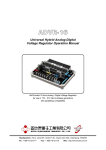
GCU-10
Automatic Engine Control Unit
Operators Manual
Headquarters : No.3, Lane 201, Chien Fu St., Chyan Jenn Dist., Kaohsiung, TAIWAN
Tel : + 886-7-8121771
Fax : + 886-7-8121775
URL : http://www.kutai.com.tw
GCU-10 Automatic Engine Control
TABLE OF CONTENTS
Section
Page
INTRODUCTION ...................................................................................................................................... 3
1. PANEL LAYOUT .................................................................................................................................... 3
1.1 Front Panel Layout ............................................................................................................................ 3
1.2 Rear Panel Layout ............................................................................................................................ 3
2. OPERATION ......................................................................................................................................... 4
2.1 Manual Operation .............................................................................................................................. 4
2.2 AUTO (Remote Start) Operation ....................................................................................................... 4
2.3 OFF Operation .................................................................................................................................. 4
3. PROTECTION SETTING AND SYSTEM WARINNG FAILURE DESCRIPTION .................................... 5
3.1 Protection Setting .............................................................................................................................. 5
3.2 Icon Referance Table ...................................................................................................................... 5
4. SYSTEM INSTALLATION .................................................................................................................... 6
4.1 Specification ...................................................................................................................................... 6
4.2 Working Environment ...................................................................................................................... 6
4.3 Panel Cut-Out .................................................................................................................................. 6
4.4 Unit Dimensions .............................................................................................................................. 6
4.5 Connection Details ............................................................................................................................ 7
4.6 Standard Wiring Diagram ( GCU-10 Without GCU-10R) .................................................................. 8
4.7 Standard Wiring Diagram ( GCU-10 With GCU-10R) ....................................................................... 9
5. TROUBLE SHOOTING ...................................................................................................................... 10
______________________________________________________________________________________
2
GCU-10 Automatic Engine Control
INTRODUCTION
1.2 Rear Panel Layout
The Model GCU-10 is an Automatic Engine Control
Module, designed to meet the demand of the
generator industry. The module starts and stops the
generator, and fault conditions, If it senses a fault it
will automatically shuts down the engine and
indicates the engine failure by means of eight LED’s.
The technician is able to adjust the settings to
enable it to work with any type of generating set and
comply with different engine conditions and
protections.
In the back, the GCU-10 has two terminal blocks J1
& J2; five adjustment pots that change the time
delay functions and five pins dip switch that set the
specification of the genset.
A--Engine Pre-Heat
Adjustable from 2 to 30sec
B--Engine Start
Adjustable from 1 to 15sec
C--Engine Stop
Adjustable from 1 to 30sec
1. PANEL LAYOUT
D--Engine Idle
Adjustable from 0 to 300sec. Set to 0 for no Idle.
1.1 Front Panel Layout
E--Engine Cool down
Adjustable from 0 to 300sec. Set to 0 for no Cool down
Operation of the GCU-10 is by a three position
waterproof switch, indicating AUTO, OFF, and
MANUAL.
Two LED's indicate POWER ON and ENGINE
RUNNING and the other eight LED's indicate the
operational status and fault conditions of the genset.
Each LED indicates; engine start failure, high water
temperature, low oil pressure, over speed, under
speed, emergency stop, and low battery voltage. An
extra LED and corresponding input can be defined
by the technician as a failure; each LED has a
picture-graph that are universally recognized.
SW 1 - Generator Frequency
ON - 50Hz
OFF - 60Hz
SW 2 - Battery Voltage
ON - 12 Volt operation
OFF - 24 Volt operation
SW 3 - Stop Solenoid
ON - Energize to Start
OFF - Energize to Stop
SW 4 - Oil Pressure Switch
ON - Normal Open NO
OFF - Normal Close NC
SW 5 - Oil Pressure Switch (Crank Disconnect)
ON - Not used for crank disconnect
OFF - Used for crank disconnect
GCU-10
KUTAI
_____________________________________________________________________________________
3
GCU-10 Automatic Engine Control
2. OPERATION
2.1 Manual Operation
To initiate a start sequence moves the front control
to MANUAL.
The
LED
above
the
knob
illuminates indicating the generator
is in MANUAL.
First the pre-heat timer begins by energizing
terminal 4. Don’t care the terminal 4 output if the
pre-heat function is no used.
After pre-heat ends, the module de-energizes
terminal 4 and begin engine starting.
The module Fuel Solenoid energizes terminal 10,
together with Engine Idle terminals 14 & 15.
After a 1 sec. delay, the starter motor engages, and
the engine cranks for the duration of the crank timer.
When the engine fires, the starter motor is
disengaged and locked out with an 18-Hertz signal
from the generator output. Alternatively, the oil
pressure switch can serve as an additional back up
crank release.
When the engine fires and the Engine Idle option is
used, the ENGINE RUNNING LED will continuous
flashing in Idle period indicating the status is IDLE.
Should the engine not fire on the first attempt and
the crank timer expires the module will once again
attempt to start the engine until the engine fires or
after the third attempt is completed.
Should the generator fail to start,
place the front knob in the OFF
(Reset) mode. Establish why the
engine failed to fire before making
any more start attempts.
After the generator starts, the module allows Oil
Pressure, High Engine Temperature, Under speed,
and the Auxiliary fault input to stabilize without
triggering any faults in 20 seconds. Once the engine
is running full fault protection is available.
2.2 Automatic (Remote Mode) Operation
By moving the knob to the "AUTO"
mode, the POWER SOURCE LED
will start flashing indicating the
module is in AUTO and the genset
can start at any time.
In the “AUTO” position, the module monitors input
terminal 9 for a “REMOTE START” signal. Should a
“REMOTE START” signal be detected a start
sequence similar to previous manual start sequence
is initiated.
When removes the Remote Start signal the Cool
Down delay timer will count down. After the Cool
Down ends, the Fuel Solenoid is ( de-energized or
energized as the case may be ) bringing the
generator to a stop and the POWER SOURCE LED
will start flashing, indicating the genset is on standby
and ready to start.
Should the Remote start signal be re-activated
during the cooling down period, the set will
immediately return to load.
NOTE
Even if the generator is executing Engine
Cool down Timer, The Module protection
system remain in operation and if any failure
occurs, the module bypasses the Engine
Cooling Timer shutting down the generator
immediately.
2.3 OFF Operation
The OFF position places the module into its Stop or
Reset mode. This will clear any alarm conditions for
which the triggering criteria have been removed.
If the engine is running and this position is selected,
the module will automatically shut down the
generator. The fuel supply will be removed and
engine will be brought to a standstill. Should a
remote start signal be present while operating in this
mode, a remote start will not occur.
By moving the knob to the OFF position, the genset
will STOP immediately.
_____________________________________________________________________________________
4
GCU-10 Automatic Engine Control
3. PROTECTION SETTING AND SYSTEM
WARINNG FAILURE DESCRIPTION
3.1 Protection Functions
Engine fail to start reattempt
Engine tries 3 times to start
Engine High Water temperature Protection
Shutdown activated after 3 seconds
Temperature Switch Type “Normally Open”
Engine Low Oil Pressure Protection
Shutdown activated after 3 seconds
Oil Pressure Switch Type
Normal Open or Normal Close
Engine Over-speed Protection
Shutdown activated after 3 seconds
If set for 50Hz operation, Over-speed is activated at
55 Hz
3.2 Icon Reference Table
ICON
DESCRIPTION
EXECUTION
Power Source
Indication
Generator
standby in Auto
LED Flashing
Generator
Operating
Normally
Engine Start
Failure
Shutdown
High Water
Temperature
Shutdown
Low Engine Oil
Pressure
Shutdown
Over-speed
Shutdown
Under-speed
Shutdown
Emergency
Shutdown
Activated
Shutdown
Spare Shutdown
Shutdown
Low Battery
Voltage Warning
Warning Only
If set for 60Hz operation, Over-speed is activated at
66 Hz
Engine Under Speed Protection
Shutdown activated after 5 seconds
If set for 50Hz operation, Under-speed is activated
at 45 Hz
If set for 60Hz operation, Under-speed is activated
at 54 Hz
Emergency Shutdown
Shutdown activated by Normal Open Contacts
Spare / User define Shutdown
Activated after 5 seconds delay
Using Normal Open Contacts
Low Battery Voltage Warning
Activated after 5 seconds delay
For 12VDC operation set at 10 V
For 24VDC operation set at 20 V
GCU-10
Start-Up Grace Period
There is 20 seconds after engine idle ends, all
alarms are ignored untile start-up grace period
expired except the emergency stop and over speed.
Once the engine is running full fault protection is
available.
KUTAI
_____________________________________________________________________________________
5
GCU-10 Automatic Engine Control
4. SYSTEM INSTALLATION
Install the Model GCU-10 Module on the front panel
by using the two installation clips provided. When
installed in a panel with too much vibration use
appropriate anti-vibration isolators.
4.1 Specification
DESCRIPTION
4.2 Working Environment
The module works over a wide temperature range
-20 to +70º C however, make allowances for
temperature rise within the control panel enclosure.
Do not mount close to any heat sources without
adequately ventilated; also, the humidity inside the
control panel should not exceed 90%.
SPECIFICATION
DC Supply
9.0 to 36 VDC
Alternator Input Range
5 ~ 300VAC
Alternator Input
Frequency
50/60 Hz
Fuel Solenoid Signal
Output
5 Amp @ 12/24VDC
Start Signal Output
5 Amp @ 12/24VDC
Warm up Signal Output
5 Amp @ 12/24VDC
Accessory “ON” Output
5 Amp @ 12/24VDC
Idle Control Conductor
Capacity
5 Amp @ 12/24VDC
Operating Temperature
-20 °C to +70 °C
Relative Humidity
90% or Below
Power Consumption
Under 3W
Weight
166 g ± 2%
4.3 Panel CUT-OUT in mm
:mm)
4.4 Unit Dimensions (Measurement:
50.0
72.0
44.0
65.5
72.0
72.0
GCU-10
KUTAI
_____________________________________________________________________________________
6
GCU-10 Automatic Engine Control
4.5 Connection Details
Seven pins din rail terminal J1
PIN No.
1
2
3
4
5
6
7
DESCRIPTION
Generator sensing Input
Generator sensing Input
Oil Pressure switch Input
Pre-heat Signal Output
Accessory “ON” Output
DC Plant Supply Input (+V)
DC Plant Supply Input (-V)
NOTES
Connect to Alternator Output
Connect to Alternator Output
Connect to Oil Pressure Switch
Connect to Internal heater. Supply (+V) 5 Amp rated
Connect to illuminate panel light. Supply (+V) 5 Amp
System DC positive input (Battery Positive)
System DC negative input (Battery Negative)
Eight pins din rail terminal J2
PIN No.
8
9
10
11
12
13
14
15
DESCRIPTION
NOTES
Spare / User Define Warning Signal Signal need to be a negative switch Input
Input
Connect to A.T.S device. Signal needs to be a
Remote Start Input
negative switch input
Connect to Fuel Solenoid or Fuel Valve Control.
Fuel Solenoid Signal Output
Supply (+V) 5 Amp
Start Signal Output
Connect to Starter Motor. Supply (+V) 5 Amp
Connect to External Emergency Stop Switch. Signal
Emergency Stop Input
needs to be a negative switch input
Connect to Water Temperature switch. Signal needs
Coolant Temperature switch Input
to be a negative switch input
Connect to Governor (Speed Control) Idle control
Idle Signal Output
Dry contacts 5 Amp rated
Connect to Governor (Speed Control) Idle control
Idle Signal Output
Dry contacts 5 Amp rated
Rear Panel layout
_____________________________________________________________________________________
7
GCU-10 Automatic Engine Control
4.6 Standard Wiring Diagram ( GCU-10 Without GCU-10R )
L
AC 5 V~ 300 V
J1-2
N
Alternator
J1-1
0.5A
J1-7
J1-6
+
Battery
10A
5A
J2-15
Idle Control
J2-14
Electronic
Governor
Idle control
5A
J1-5
Accessory "ON"
5A
J2-10
Stop
5A
J2-11
Start
5A
J1-4
Pre-Heat
GCU-10 GENERATOR CONTROL UNIT
J2-9
Remote Start
J2-8
AUX. Alarm
J2-12
Emergency Stop
J2-13
Temp SW
J1-3
OIL SW
_____________________________________________________________________________________
8
GCU-10 Automatic Engine Control
4.7 Standard Wiring Diagram ( GCU-10 With GCU-10R )
J1-4
J2-11
J2-10
From
GCU
5A
J2-15
Idle Control
J2-14
Electronic
Governor
Idle control
J2-9
Remote Start
J2-8
AUX. Alarm
J2-12
Emergency Stop
J2-13
Temp SW
J1-3
OIL SW
5A
J1-5
Accessory "ON"
GCU-10 GENERATOR CONTROL UNIT
J1-7
5A
J1-6
J4-8
5A
J1-2
J4-7
5A
J1-1
J4-6
To
Genset
GCU-10R
35A
J3-8
J4-5
35A
J3-7
J4-4
35A
J3-6
J4-2
35A
J3-5
J4-1
0.5A
J3-4
Battery
+
Stop
J3-2
N
Start
J3-1
L
Alternator
5~ 300 VAC
Pre-Heat
_____________________________________________________________________________________
9
GCU-10 Automatic Engine Control
5. TROUBLE SHOOTING
SYMPTOM
In “MANUAL MODE”
Power Source LED does
not
illuminate
and
generator can not start.
PLEASE CHECK
REMEDY
• Check Battery Volts on cranking (Not • Change Battery
below 6V)
• Check DC supply Voltage
• Check and confirm voltage and
wiring
• Check DC supply fuse
• Change fuse
• None of the above
• Change Control Unit
• Check Battery Volts on cranking (Not • Change Battery
below 6V)
In
“MANU
MODE”
Power Source Indication
illuminates and Starter
Motor fails to operate.
• Check oil pressure switch type
• Correct Oil pressure Switch type
to correct setting
• Check GCU-10 Start signal output
• Change Control Unit
• Check Starting motor
• Change Starting motor
• Check wiring to see if it is open circuit • Correct the fault point
In “MANUAL MODE”
Power Source LED
illuminates and Starter
Motor ails to crank.
• Check fuel
• Add fuel
• Check wiring of fuel solenoid
• Correct Engine Stop Mode setting
• Check Governor and wiring
• Change Governor
• Check Battery Volts on cranking (Not • Change Battery
below 6V)
In “MANUAL MODE”
Starter Motor cranks but
engine fails to fired
Starting motor does not
disengage
after
generator starts
Emergency stop always.
Engine not operating
And does not start
Low oil pressure always
while engine is running
• Check Starting circuit and wiring
• Change Wiring
• Check oil pressure Switch
• Change appropriate oil pressure
switch or cancel the Oil Pressure
Detection Engine Start option
• Check AC Input Voltage (5~300VAC)
• Change
Automatic
Regulator (AVR)
Voltage
• Check wiring to see if it is open circuit • Correct the fault point
• Check oil pressure switch
• Change appropriate oil pressure
switch
• Check Starter motor
• Change Starting Motor
• Check emergency stop terminal and • Select emergency stop to normal
open input
wiring
• Check wiring to see if it is short circuit • Correct the wiring
• Check engine oil pressure
• Add engine oil / lubricant
• Check oil pressure switch
• Change oil pressure switch
• Check wiring to see if it is open circuit • Correct the fault point
High water Temp always
while engine is running
• Check engine temperature
• Change water temperature switch
• Check water temperature switch
• Correct the fault point
• Check wiring for short circuit
_____________________________________________________________________________________
10
GCU-10 Automatic Engine Control
SYMPTOM
In "Auto Mode" the
generator does not start
with a remote start
signal
PLEASE CHECK
REMEDY
• Check Engine Pre-heat countdown
Setting to see if preset time (2 ~ 30
sec)has been reached
• Check remote start signal input
• Correct the fault point
• Check GCU-10 start signal output
• Change Control Unit
• Check wiring to see if it is open circuit • Correct the fault point
Pre-heat does not work
• Check Engine Pre-heat Countdown • Reset settings
Setting
• Check GCU-10 Pre-heat signal output • Change Control Unit
• Check Engine Cooling Countdown • Reset
Engine
time setting (excessive time delayed)
Countdown time
Cooling
• Check Engine Stop Countdown time
setting (inadequate time delayed)
Engine does not be
stopped in off mode
• Check Engine Stop Mode setting
• Reset Engine Stop Countdown
time
• Check GCU-10 Engine Shutdown • Reset Engine Stop Mode Change
Control Unit
output signal
• Check Fuel Solenoid
• Change Fuel Solenoid
_____________________________________________________________________________________
11