1
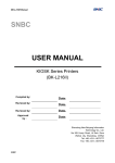
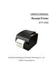
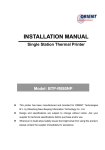
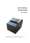
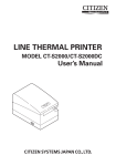
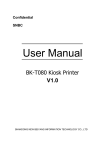
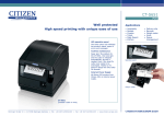
USER’S MANUAL Receipt Printer BTP-R580Ⅱ Shandong New Beiyang Information Technology Co., Ltd BTP-R580Ⅱ User’s Manual Declaration Information in this document is subject to change without notice. SHANDONG NEW BEIYANG INFORMATION TECHNOLOGY CO., LTD. (hereinafter referred to as “SNBC”) reserves the right to improve products as new technology, components, software, and hardware become available. If users need further data about these products, please feel free to contact SNBC or your local dealer. No part of this document may be reproduced or transmitted in any form or by any means for any purpose without the express written permission of SNBC. Copyright Copyright © 2011 by SNBC Printed in China Version 1.0 Trademark Registered trademark of SNBC: Warning and caution Warning: Items shall be strictly followed to avoid injury or damage to body and equipment. Caution: Items with important information and prompts for operating the printer. SNBC has been approved by the following certifications: ISO9001 Quality Control System ISO14001 Environmental Management System OHSAS18001 Occupational Health and Safety Management System IECQ QC080000 Hazardous Substance Process Management System BTP-R580Ⅱ has been approved by the following certifications of environmental protection: -1- BTP-R580Ⅱ User’s Manual Safety instructions Before installing and using the printer, please read the following items carefully: 1. Safety warning Warning Do not touch the cutter of the printer. Warning The print head is a thermal element and it is at a high temperature during printing or just after operation, therefore do not touch it or its peripherals for reasons of safety. Warning The print head is an ESD-sensitive device. To avoid damage, do not touch either its printing parts or connecting parts. 2. Cautions 1) Install the printer on a flat and stable surface; 2) Reserve adequate space around the printer so that convenient operation and maintenance can be performed; 3) Keep the printer far away from water source, and do not expose the printer to direct sunlight, strong light and heat; 4) Do not use or store the printer in a place exposed to high temperature, high humidity or serious pollution; 5) Do not place the printer in a place exposed to vibration or impact; 6) No condensation is allowed to the printer. In case of such condensation, do not turn on the power until it has completely gone away; 7) Connect the printer power to an appropriate grounding outlet. Avoid sharing one electrical outlet with large power motors or other devices that may cause the fluctuation of voltage; 8) Disconnect the power when the printer is deemed to idle for a long time; 9) Don’t spill water or other electric materials into the printer (e.g. metal). In case this happens, turn off the power immediately; 10) Do not allow the printer to start printing when there is no recording paper installed; otherwise the print head and platen roller will be damaged; 11) To ensure quality print and normal lifetime, use recommended paper or its equivalent; 12) Shut down the printer when connecting or disconnecting interfaces to avoid damages to control board; 13) Set the print darkness to a lower grade as long as the print quality is acceptable. This will help to keep the print head durable; 14) Do not disassemble the printer without permission of a technician, even for repairing purpose; 15) Keep this manual safe and at hand for reference purpose. -2- BTP-R580Ⅱ User’s Manual Contents 1 Overview ..................................................................................................................... - 1 1.1 Introduction........................................................................................................... - 1 1.2 Main features .........................................................................................................- 1 - 2 Specifications .............................................................................................................. - 2 2.1 Technical specifications..........................................................................................- 2 2.2 Cutter specifications ..............................................................................................- 3 2.3 Paper specifications ...............................................................................................- 3 2.3.1 Parameters of continuous thermal paper ..................................................... - 3 2.3.2 Parameters of marked paper ....................................................................... - 3 2.4 Print and tear-off position .......................................................................................- 5 2.4.1 Print position .............................................................................................. - 5 2.4.2 Tear-off position .......................................................................................... - 5 - 3 Appearance and modules............................................................................................. - 6 3.1 Appearance and modules .......................................................................................- 6 3.2 LED and buzzer .....................................................................................................- 7 - 4 Printer installation ........................................................................................................ - 9 4.1 Unpacking..............................................................................................................- 9 4.2 Printer installation ..................................................................................................- 9 4.3 Power connection ..................................................................................................- 9 4.4 Connect interface cable ....................................................................................... - 10 4.5 Connect USB cable .............................................................................................. - 10 4.6 Connecting the cash drawer ................................................................................. - 10 4.7 Install paper roll ................................................................................................... - 11 4.7.1 Confirm paper type ....................................................................................- 11 4.7.2 Install/replace paper roll.............................................................................- 11 4.8 Paper near end position adjustment ..................................................................... - 12 4.9 Power-on and self-test ......................................................................................... - 12 4.9.1 Power on the printer ................................................................................. - 12 4.9.2 Print self-test page.................................................................................... - 12 -3- BTP-R580Ⅱ User’s Manual 5 Routine maintenance ................................................................................................. - 13 5.1 Clean print head and platen roller......................................................................... - 13 5.2 Clean sensors ...................................................................................................... - 13 5.3 Clear paper jam ................................................................................................... - 13 - 6 Interface signal .......................................................................................................... - 13 6.1 Parallel interface .................................................................................................. - 14 6.2 Serial interface..................................................................................................... - 15 6.3 USB interface ...................................................................................................... - 15 6.4 Ethernet interface ................................................................................................ - 15 6.5 WLAN interface.................................................................................................... - 16 6.6 Power interface definition ..................................................................................... - 17 6.7 Signal definition of cash drawer interface ............................................................. - 17 - 7 Troubleshooting ......................................................................................................... - 18 7.1 Printer doesn’t work ............................................................................................. - 18 7.2 ERROR LED and Buzzer alarm ............................................................................ - 18 7.3 Problems during printing ...................................................................................... - 18 - 8 Options...................................................................................................................... - 19 8.1 Kitchen printing prompt device ............................................................................. - 19 - 9 Power management ................................................................................................... - 20 - Appendix: Button configuration table ................................................................................. - 21 - -4- BTP-R580Ⅱ User’s Manual 1 Overview 1.1 Introduction BTP-R580Ⅱ is a high performance thermal printer, which can be widely used for real-time printing applications, such as POS system, restaurant system, ATM, etc. BTP-R580II can be connected with other devices via parallel, serial, USB, Ethernet or WLAN interface and can provide drivers for operating systems such as WINDOWS 2000/XP/Server2003/VISTA/ Server2008/WIN7, Linux, MAC and UPOS middleware. 1.2 Main features ¾ Low noise, high print speed 230mm/s; ¾ Easy paper loading; ¾ Easy use and maintenance; ¾ Marked paper and continuous paper available; ¾ Compatible with various paper width between 54.5~82.5mm; ¾ Cutting paper automatically; ¾ Cash drawer control interface; ¾ Communication interface optional; ¾ ESC/POS compatible; ¾ Volume of buzzer can be adjusted; ¾ Function of saving paper; ¾ Low power consumption design (Min. power consumption is lower than 1W): the default waiting time of entering sleep mode is 5 minutes. -1- BTP-R580Ⅱ User’s Manual 2 Specifications 2.1 Technical specifications Item Print method Print resolution Parameter Direct thermal line 203×203DPI Print speed Max. 230mm/s Print width Max. 80mm Paper type Barcode type Character Character enlargement Character rotation Continuous paper, marked paper One-dimensional barcode: UPC-A, UPC-E, EAN-8, EAN-13 , Codabar, Code39, Code128, Code93, ITF Two-dimensional barcode: PDF417, QR, Maxicode GS1 barcode Font A: 12×24 Font B: 9×17 Kanji Font A: 24×24 Optional: Simplified Chinese, Korean, Traditional Chinese, Japanese, English Codepage: 56 kinds of codepages International character sets: 14 kinds; All characters can be enlarged 1-6 times horizontally and vertically. Rotation printing in four directions (0°, 90°, 180°, 270°) Paper near end detection Photoelectric sensor Paper end detection Photoelectric sensor Paper existence detection Top cover position detection Print head temperature detection Photoelectric sensor Micro switch Thermal resistor Bitmap download Image processing Communication interface Cash drawer interface Memory Power supply Print head lifetime Operating temperature and humidity Storage temperature and humidity External dimensions Direct bitmap printing Download buffer size: Support bitmap print mode and realize RAM: 128KB fast image printing. FLASH: 256KB Standard parallel interface or RS232 serial interface, RS485 interface, USB interface, Ethernet interface, WLAN interface (optional) Can control 2 cash drawers. RAM: 2MB FLASH: 2 MB /4MB 110-240VAC, 50/60Hz ≥150Km (standard test sample with 12.5% duty ratio) 5~45℃, 20%~90% (40°C) -40~60 ℃ , 20% ~93% (40 ℃ ) 155.5 (W) ×205 (D) ×160 (H) mm -2- BTP-R580Ⅱ User’s Manual 2.2 Cutter specifications Item Parameter Cutting mode Sliding blade Cutting time 600ms Cutting interval 2s Applicable paper type 0.06~0.1mm Operating voltage 24VDC Max. operating current 1.2A Cutter lifetime 2 million cuts Remarks The time that one cut takes 30 cuts/min (Max.) Thermal paper or paper with the same thickness 24VDC *Including full cut and partial cut * Full cut: Paper is cut off completely; * Partial cut: A small part in the middle of paper is left uncut. It is forbidden to feed paper backward in case the uncut part causes paper jam. 2.3 Paper specifications 2.3.1 Parameters of thermal continuous paper ¾ Paper type: Thermal continuous paper ¾ Paper supply method: Paper roll ¾ Paper width: 54.5±0.5 mm~82.5±0.5 mm ¾ Paper thickness: 0.06mm-0.1mm ¾ Thermal layer: Outward ¾ Paper roll specifications: OD(MAX): ф100 mm ¾ Recommended paper: 2.3.2 Paper model Manufacturer F240AC,F220-VP,FV230A1 PA220AG,HP220A Mitsubishi Paper Mill CO., LTD FD210,PD150R,PD160R OJI Paper CO., LTD. F70NA FUJI PHOTO FILM CO., LTD Parameters of marked paper BTP-R580Ⅱ can support marked paper printing and set the cutting and initial printing position accurately. Marked paper not only should meet the parameters of thermal paper roll, but also should meet the following requirements: -3- BTP-R580Ⅱ User’s Manual L1 mark height: 3mm≤L1≤13mm L2 mark length: L2≥12mm L3 mark spacing: 20mm≤L3<500mm Mark position: The mark can be set on the left, middle or right, and when it is on the left or right, only 80mm paper is available. Reflectivity: The reflectivity of the marked part must be no more than 15% while the reflectivity of the rest part should be higher than 85%. There should be no patterns like advertisement or poster between two marks. Caution: To ensure quality print and normal lifetime, use recommended paper or its equivalent; Paper cannot be stuck on the paper roll core; If the paper is contaminated by chemical substances or grease, the contaminated part may fade or be printed unclearly; To ensure print effect, do not let hard objects scratch the thermal layer; When the temperature exceeds 70°C, the thermal layer will fade. Thus, do not use or store the paper in a place exposed to high temperature, high humidity, strong light, etc.; The mark is measured when printing or feeding paper. If the sensor detects the mark is higher than the default setting (default setting is 13mm), the printer will enter paper end error status. -4- BTP-R580Ⅱ User’s Manual 2.4 Print and tear-off position 2.4.1 Print position L1 paper cabinet width: 83.5+0/-0.5mm L2 effective print width: 80mm L3 distance from print head to left edge of paper cabinet (fixed width): 1.75±1mm L4 distance from print head to right edge of paper cabinet (fixed width): 1.75±1mm L5 left margin: The default value is 8mm. L6 width of print area: Set by command (refer to Programming Manual), default value: 64mm L7 right margin: The default value is 8mm. 2.4.2 Tear-off position L1: about 30mm L2: about 13mm -5- BTP-R580Ⅱ User’s Manual 3 Appearance and modules 3.1 Appearance and modules 1—paper guide 2—paper near end sensor lever 3—mark sensor 4—platen roller 5—cutter 6—cutter cover board 7—tear-off bar 8—fixed blade 9—print head 10—guard board for print head 11—roller 12—cover open lever 13—top cover 14—middle cover 15—bottom cover 16—thumb wheel 17—power switch 18—power interface 19—communication interface 20—USB interface 21—cash drawer interface 22-POWER LED 23-ERROR LED 24-PAPER LED 25-FEED button Functions of some modules: a) Paper guide Move the paper guide in paper cabinet continuously by turning the thumb wheel so as to adapt to various paper width 54.5±0.5 mm~82.5±0.5 mm. b) Power switch Press down “O” to turn off the printer and press down “—” to turn on the printer. c) FEED button Feed paper: Printer will feed paper when the FEED button is pressed down in normal status. Printer will feed paper continuously if holding the button. -6- BTP-R580Ⅱ User’s Manual Print configuration sample: Pressing down the FEED button while turning on the printer, the printer will print out configuration sample, including print length, print width, print speed, etc. Enter button configuration mode: Pressing down FEED button while turning on the printer, the printer will print out configuration sample, then cut paper and enter waiting status (ERROR LED flashes). The printer will enter button configuration mode if pressing down the FEED button for a long time at this time. Refer to Appendix Button Configuration Table for detailed function and operation methods of button configuration mode. d) POWER LED Indicate power status (ON/OFF). e) ERROR LED Indicate error status of printer: in normal status, ERROR LED is off; in error status (e.g. print head lift-up, abnormal voltage, print head overheating, cutter error, mark location failure), ERROR LED flashes. f) PAPER LED Indicate paper status: in normal status, PAPER LED is off; PAPER LED flashes when paper status changes (paper end or paper near end). g) Paper end sensor Used to detect whether there is paper or not. 3.2 LED & buzzer 1) Functions of LED & buzzer Name Status POWER LED (green) Always on Printer is in power-on status. Off Printer is in power-off status. Flash ERROR LED (red) Printer is in error status. Printer is in normal status (except for paper near end). Off Always on PAPER LED (red) Paper status is abnormal. Printer is executing macro definition or in waiting status. Flash Off Buzzer Explanation Printer is in normal status. Beep Printer is in error status. 2) Error type indicated by LED & buzzer Error type Print head overheating Input voltage abnormal Cutter error Print head lift-up Paper end Paper near end Mark location failure or calibration error ERROR LED Cycle Cycle Cycle Cycle Cycle flash flash flash flash flash Off 6 5 4 3 2 times times times times times Cycle flash 1 time -7- PAPER LED Off Off Off Off Off Always on Off Buzzer Cycle Cycle Cycle Cycle Cycle beep 6 beep 5 beep 4 beep 3 beep 2 None times times times times times Cycle beep 1 time BTP-R580Ⅱ User’s Manual Caution: The temperature of the print head is detected by a thermal resistor. If the print head is overheating, the protective circuit will shut off the power and force the printer to stop printing; the temperature of print head when printing is stopped is 65 ℃ . -8- BTP-R580Ⅱ User’s Manual 4 Printer installation 4.1 Unpacking Check if all the articles listed in the packing list are here and in good condition. If any problem, please contact SNBC or the dealer. 4.2 Printer installation 1) Printer should be installed on a flat and stable place; horizontal installation is recommended and the inclination angle should not exceed ±10° in inclination installation (in paper feed direction), no inclination in other directions; 2) Printer should be far away from water source; 3) Avoid putting the printer in a place exposed to vibration and impact; 4) Printer should be grounded securely; 5) To ensure the operation reliability and easy operation of printer, it is recommended to reserve proper space during operation and maintenance. 4.3 Power connection 1) Ensure the printer is turned off; 2) Insert the power cord into the power socket on the back of printer; 3) Fit the power cord into the cable hook. -9- BTP-R580Ⅱ User’s Manual Caution: When the printer is bound to idle for a long period of time, disconnect the power cord. When the power is burned out or cannot be used for other reasons, replace it according to the following steps: 1) Press the power cover board and take it off in the direction indicated by the arrow; 2) Pull the plug out of the printer and move the power in the direction indicated by the arrow until it cannot be moved; 3) Take the power out; 4) Replace the power with a new one in reverse order. 4.4 Connect interface cable 1) Ensure the power switch is turned off; 2) Insert the interface cable ( Ⅰ in the figure) into the suitable interface and fix the plug (screw or latch spring); 3) Connect the other end of the interface cable to the host. 4.5 Connect USB cable 1) Ensure the power switch is turned off; 2) Insert the USB cable (Ⅱ in the figure) into the USB interface; 3) Connect the other end of the interface cable to the host. 4.6 Connecting cash drawer cable 1) Ensure the printer power is turned off. 2) Insert the cash drawer cable ( Ⅲ in the figure) into the cash drawer interface on the back of the printer. Caution: Cash drawer interface can be connected only with a cash drawer device (cannot be connected with a telephone line, etc.). - 10 - BTP-R580Ⅱ User’s Manual 4.7 Install paper roll 4.7.1 Confirm paper type Paper can be installed after the connection of power cable and interface cable. But before starting printing, the paper type must be confirmed first. 4.7.2 Install/replace paper roll 1) Turn off the printer; 2) Press the cover open lever to lift up and open the top cover; 3) Place a paper roll into the paper cabinet; 4) Pull the paper head out, close top cover and tear off the surplus portion of the paper. Caution: Adjust the paper guide according to the paper specification as follows: adjust paper guide to the maximum width and place paper roll into paper cabinet; move paper guide to the proper position by turning thumb wheel according to paper width (1mm gap must be reserved between paper guide and paper roll in case paper roll is jammed); the paper roll should be rolled according to the requirements of the printer; Ensure that the paper roll is rolled tightly; otherwise paper jam or other error may occur. The paper roll should be placed in the paper cabinet stably without inclination; otherwise it may affect the printing. - 11 - BTP-R580Ⅱ User’s Manual 4.8 Paper near end position adjustment Paper roll with different core can be used by adjusting paper near end sensor lever to the corresponding level with the minimal remaining amount of paper at level 1. Level Level 1 Level 2 Level 3 Level 4 Level 5 Level 6 Core diameter A (mm) 15 18 21 24 27 30 A: core ID B: core OD C: paper roll OD Caution: The factory default position of paper near end sensor lever is at level 1. The requirement for the core with big diameter can be met by adjusting paper near end sensor lever; When using core with different diameter, the remaining amount of paper may be different at the same level. 4.9 Power-on and self-test 4.9.1 Power on the printer 1) Ensure the printer is connected with power supply; 2) Turn on the power switch to power on the printer. 4.9.2 Print self-test page 1) Ensure that the printer is connected with power supply and that paper roll is installed; 2) Ensure the printer is turned off; 3) Press down the FEED button while turning on the printer, then release the button. The printer will print out the configuration information and the prompt characters “Press and Release FEED key to print characters” and “Press and Hold FEED key to config the printer”. Then the printer enters waiting status while the PAPER LED is flashing. 4) Pressing down the FEED button for a short time, the printer will print a character test sample to end self-test page printing. 5) To continue with step 3, pressing down the FEED button for a long time, the printer will enter button configuration mode. Refer to Appendix Button Configuration Table for detailed function and operation method of button configuration mode. - 12 - BTP-R580Ⅱ User’s Manual 5 Routine maintenance Caution: Before starting routine maintenance, ensure that the printer power is turned off; Do not use solvents like gasoline or acetone; When cleaning sensors, the printer should not be powered on until the pure alcohol has completely evaporated. It is recommended that the maintenance cycle should be no longer than one month. 5.1 Clean print head and platen roller Follow the steps below to clean print head and platen roller: 1) Turn off the printer power and open the top cover; 2) If the printer has just finished printing, please wait until the print head has completely cooled down; 3) Use alcohol cotton (wrung out) to wipe off the dust and stains on the surface of print head and platen roller; 4) Wait until the alcohol has completely evaporated, then close the top cover. 5.2 Clean sensors When the printer cannot identify the paper or mark effectively, the sensor should be cleaned, with cleaning steps as follows: 1) Turn off the printer; 2) Press the cover open lever to open the top cover of the printer; 3) Use soft cotton cloth dipped with pure alcohol (wrung out) to wipe off the dust and stains on the surface of the sensor; 4) Wait until the pure alcohol has completely evaporated, then close the top cover to end sensor cleaning. 5.3 Clear paper jam When any of the following cases occurs, clear paper jam: ¾ Paper cannot be sent out normally; ¾ Abnormal noise occurs when feeding paper. Follow the steps below to clear paper jam: 1) Turn off the printer power; 2) Press the top cover open lever to open the top cover of printer; 3) Check the paper path. If paper is jammed in paper path, take the crinkled paper away and trim the paper head; 4) Close top cover to end paper jam clearing. - 13 - BTP-R580Ⅱ User’s Manual 6 Interface signal 6.1 Parallel interface Parallel interface can work in IEEE 1284 compatible mode or nibble mode. The interface is 36-pin socket. The Interface is defined as below: Pin # Signal source Signal definition 1 H nStrobe 2 H Data 0 (Least Significant Bit) 3 H Data 1 4 H Data 2 5 H Data 3 6 H Data 4 7 H Data 5 8 H Data 6 9 H Data 7 (Most Significant Bit) 10 P nAck 11 P Busy 12 P Perror 13 P Select 14 H nAutoFd 15 Not defined 16 Logic Gnd 17 Chassis Gnd 18 P Peripheral Logic High 19 Signal Ground (nStrobe) 20 Signal Ground (Data 1) 21 Signal Ground (Data 2) 22 Signal Ground (Data 3) 23 Signal Ground (Data 4) 24 Signal Ground (Data 5) 25 Signal Ground (Data 6) 26 Signal Ground (Data 7) 27 Signal Ground (Data 8) 28 Signal Ground (PError, Select, and nAck) 29 Signal Ground 30 (Busy and nFault) Signal Ground (nAutoFd, nSelctIn, and nInit) 31 H nInit 32 P nFault Not defined 33 - 14 - BTP-R580Ⅱ User’s Manual 34 Not defined 35 Not defined 36 H nSelectIn 6.2 Serial interface The serial interface of the printer is compatible with RS-232, and the interface socket is DB25 female. PIN No. Signal definition PIN1 Frame ground PIN2 TXD PIN 3 RXD PIN 4 RTS PIN 5 Not connected PIN6 DSR PIN 7 Signal ground PIN 8~19 Not connected PIN 20 DTR PIN 21~25 Not connected User can query interface setting status via printing configuration sample; the default settings of serial interface are as follows: Baud rate: 19200bps, data bit: 8 bits, parity: none, stop bit: 1, handshake: DTR/DSR 6.3 USB interface 1) Parameters Data transmission: Support USB2.0 protocol. Connector (Printer side): USB A series socket, support USB HUB. 2) 3) Definition and functions of interface signals PIN No. Signal name Description 1 VBUS +5V 2 DATA- Printer data transmit line minus 3 DATA+ Printer data transmit line plus 4 GND Ground Interface connector 6.4 Ethernet interface 1) Interface features ¾ Support 10BASE-T communication ¾ Compatible with Ethernet II standard - 15 - BTP-R580Ⅱ User’s Manual ¾ LED displays network connecting status and data transmission status ¾ Support 9100 port print ¾ Support status back ¾ Support parameter configuration ¾ Support firmware online update ¾ Support printer status query and interface module maintenance based on HTTP (only supported by JK-E02 interface, not supported by JK-E04 interface). 2) Interface signal definition Interface adopts 10BASE-T standard in accordance with IEEE802.3. The interface signal is defined as below: Pin Signal name Explanation 1 TX+ Data transmission + 2 TX- Data transmission - 3 RX+ Data receiving + 4 NC Reserve 5 NC Reserve 6 RX- Data receiving - 7 NC Reserve 8 NC Reserve Table 6.4-1 Interface module pin list Figure 6.4-1 Interface connector 6.5 WLAN interface 1) Interface features ¾ Support 802.11b, 802.11g communication ¾ Support 9100 port printing, LPR printing ¾ Support status back ¾ Support parameter configuration ¾ Support firmware online update ¾ Support HTTP function 2) Supported protocols ¾ IP ¾ ARP ¾ ICMP ¾ TCP ¾ UDP - 16 - BTP-R580Ⅱ User’s Manual ¾ DHCP ¾ TFTP ¾ HTTP Wireless interface module uses wireless USB network card. For the main technical specifications, please contact your local dealer or SNBC. 6.6 Power interface definition Power interface signal definition Pin Signal name 1 E 2 L 3 N Figure 6.6-1 Power socket 6.7 Signal definition of cash drawer interface 1) Electrical features ¾ Driving voltage: DC 24V ¾ Driving current: Max. 1A ¾ Cash drawer status detection signal: “L” = 0~0.5 V “H” = 3.3 V 2) Cash drawer interface socket adopts RJ-11 6P connector 3) Interface signal definition No. Signal 1 FG 2 DRAWER 1 3 DRSW 4 VDR 5 DRAWER 2 6 GND Function Frame ground Driving signal of cash drawer 1 Cash drawer status detection signal Cash drawer driving power Driving signal of cash drawer 2 Circuit share ground Caution: Do not connect or disconnect the plug of communication cable when printer power is on; Communication cable should be far away from strong current; Always use shielded communication cables. - 17 - BTP-R580Ⅱ User’s Manual 7 Troubleshooting Refer to this chapter for solution when a problem occurs. If the problem still cannot be solved, please contact your local dealer or SNBC for assistance. 7.1 Printer doesn’t work Problem Possible causes LED is off and the printer doesn’t work. Solution Printer is not connected with power supply. Connect the power supply. printer with Printer is not turned on. Turn on the power switch. Circuit board is damaged. Contact your local dealer or SNBC. 7.2 ERROR LED and buzzer alarm Problem Possible causes Solution PAPER LED is on and buzzer beeps. Paper end Replace paper roll. PAPER LED is on. Paper near end Replace paper roll. Input voltage abnormal Print head overheating ERROR LED buzzer beeps. flashes and Turn off the printer and check input voltage. Turn off the printer and wait for print head to cool down. Print head lift-up Close print head top cover. Cutter error Reset cutter (power on again). Printer is damaged. seriously Contact your local dealer or SNBC. 7.3 Problems during printing Problem Possible causes Solution Printout is unclear. Print head damaged Printout is unclear or dirty. Dirty print head or feed roller Clean print head or feed roller. Paper jam Open top cover, check paper path and clear paper jam. Paper cannot be outputted normally. - 18 - Replace print head. BTP-R580Ⅱ User’s Manual 8 Options 8.1 Kitchen printing prompt device - 19 - BTP-R580Ⅱ User’s Manual 9 Power management The power management of BTP-R580Ⅱ has four operation modes: off, ready, active, sleep. Printer will enter ready mode after the printer is turned on or completes printing task; Printer will enter sleep mode if there is no printing task for 5 minutes in ready mode; Printer will awake automatically and enter active mode when printing task comes, and will enter ready mode again after completing the printing task; Related parameters of power management are as below: Maximum default delay time of entering sleep mode is less than 5 minutes; Since the maximum default delay time is less than 5 minutes, BTP-R580Ⅱ does not open the interface of changing this time to user. - 20 - BTP-R580Ⅱ User’s Manual Appendix: Button configuration table Refer to BTP-R580II Firmware Button Configuration Table. - 21 -