1
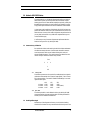
14 July 1998
CSIRO Division of Marine Research
RSV Southern Surveyor Data Collection System
Ashtech ADU2 GPS
Installation and Configuration Notes
Pamela Brodie
CSIRO Division of Marine Research
Hobart, Tasmania, Australia
Version 1.01: July1998
©1998, CSIRO Division of Marine Research
Describes the installation, calibration results and the commands required
for SSGPA logging and the use of the ADU2 with the Broadband Acoustic
Doppler Profiler
References
ADU2 Operation and Reference Manual, December 1996, Ashtech
[AORM]
Ashtech ADU2 Attitude Determination Unit Installation for the CSIRO
Vessel ‘Southern Surveyor’ Completed 28-29 January 1998, January 1998,
Sagem [ADUI]
The Southern Surveyor BBADCP Logging System User Manual 1.0, April
1998 CSIRO [SSLS].
Survey for Orientation of GPS Antennae on Research Vessel Southern
Surveyor, correspondence and drawing, Roger Boxall & Associates, 15
April 1998
Contact
Sagem, the Ashtech supplier Phone 02 93153500
Robyn Tan is the contact through: [email protected]
2
Ashtech ADU2 GPS
Ashtech ADU2 GPS Notes
1.0 Ashtech ADU2 GPS Notes
The Ashtech ADU2 is a GPS-based 3 dimensional position and altitude
determination system. As well as position data, this Ashtech outputs
heading, pitch and roll. These attitude readings are primarily used by the
Broadband Acoustic Doppler Current Profiler on the Southern Surveyor.
They provide important rotation corrections to BBADCP measurements.
In late January the installation of the Ashtech ADU2 GPS unit was completed. The fixed four antenna array was connected to the A frame 11.5m
above the water. A survey of the antenna alignment was performed on 28
January 1998, and antenna array calibrations completed during a test
cruise the following day.
A confirmatory survey of antenna alignment was performed when the
Southern Surveyor was in dry dock (April 1998).
1.1
Antenna Array Calibration
For attitude calculations to be made by the ADU2 the distances between
the reference antenna (Antenna 1) and the other three GPS antennae
must be measured. There are two methods of doing this, static and
dynamic [AORM Chapter 4]. The resulting vectors are entered into the
receiver. The plan view of the antenna array is below.
Fore
3
2
4
1
Aft
1.1.1
January 1998
The following vectors were the result of the combined static and dynamic
calibrations conducted by Luke Tilyard of Sagem [ADUI]. The 1-3 Vactor
Z(U) value marked by * was used on SS9801 and SS9802, prior to receiving the written report.
1-2 Vector
1-3 Vector
1-4 Vector
1.1.2
X(R)
0.000
-3.003
2.997
Y(F)
5.998
5.996
6.005
Z(U)
0.000
0.000 (0.001*)
-0.001
April 1998
The data acquired for a static calibration during dry-dock (April 1998)
were examined, but there were problems with calculating the baseline
summary and no calibration was obtained.
1.2
Heading Offset Angle
Measurement of the alignment of Antenna 1 and 2 with the heading
direction of the Southern Surveyor was difficult while the ship was in the
Ashtech ADU2 GPS
3
Ashtech ADU2 GPS Notes
water as was the case during the installation survey (January 1998). A
further survey was performed when the ship was in dry-dock (April 1998).
1.2.1
January 1998
After the initial installation survey an offset of +0.123˚ from the heading
direction of the Southern Surveyor was used during voyages SS9801 and
SS9802. However the Sagem installation report [ADUI] which became
available after SS9802 indicated a measurement of -0.123˚.
1.2.2
April 1998
The dry dock survey (April 1998) resulted in the offset angle of -0.31˚.
NOTE: It would be necessary to apply the result of the dry dock survey,
and correct for the mistaken offset angle which was used, to GPA heading
data collected on SS9801 and SS9802: -0.433˚. The ADCP data do not
require correction.
1.3
Configuration of Calibration Results
The command $PASHQ,3DF queries the configuration of the attitude
parameters of the of the ADU2.
The commands to set the relative position vectors from antenna 1 to each
of the other antennae would normally be entered only once after a calibration. The settings should be retained in memory until the next calibration
is run. If saved they are cleared only with the command $PASHS,INI.
The command to reset the receiver parameters to defaults ($PASHS,RST)
does NOT wipe these settings. The commands which are sent are $PASHS,3DF,V12,+0.000,+5.998,+0.000
$PASHS,3DF,V13,-3.003,+5.996,+0.000
$PASHS,3DF,V14,+2.997,+6.005,-0.001
$PASHS,3DF,OFS,-0.310,+0.000,+0.000
The commands entered MUST be saved:
$PASHS,SAV,Y
NOTE: All commands which have been sent to the unit must get the
response $PASHR,ACK*3D. Upper-case characters are required.
The five commands above can be entered into the unit using a PC running
Ashtech terminal software Remote or Terminal.
The commands were added to a software down-load from the Sun, as the
other settings such as data requests are sent. The commands can also be
sent through a telnet session on the Sun to Annex1 Port 15.
4
Ashtech ADU2 GPS
Ashtech ADU2 GPS Notes
1.4
Data Requests
1.4.1
SSGPA Settings
The user settings required for both ports are normally sent to the instrument by the SSGPA Input Controller from the User Interface of the
Southern Surveyor Data Collection System.
The following commands are sent $PASHS,RST
$PASHS,NME,VTG,A,ON
Three commands for the Port A data stream
$PASHS,NME,GGA,A,ON
$PASHS,NME,PAT,A,ON
$PASHS,NME,HDT,B,ON
Three commands for the Port B data stream
$PASHS,NME,VTG,B,ON
$PASHS,NME,PAT,B,ON
$PASHS,3DF,ANG,45
$PASHS,NME,PER,1
Optional: set NMEA message time interval 1 sec (default 0.5 sec)
$PASHS,SAV,Y
As noted above, if necessary these commands can be entered manually
through a Sun Telnet session, or on a PC through Terminal or Remote
(the Ashtech serial port software).
Port A is used by the SSGPA Input Controller (Annex1 Port 2015).
Port B is used by the RDI Transect ADCP data logging software on the
PC.
1.4.2
Transect Settings
The following commands are to set up the port B data stream for the
Transect PC only. Establish a Terminal or Remote session with port B of
the Ashtech and type as follows.
$PASHS,NME,ALL,B,OFF
$PASHS,NME,HDT,B,ON
$PASHS,NME,VTG,B,ON
$PASHS,NME,PAT,B,ON
$PASHS,SAV,Y
Note that the Transect PC should have the serial line from port B of the
Ashtech split between two comms ports. Also note, it is not possible to
talk to the ADU2 receiver with both ports connected through this split
cable.
1.5
Performance of Ashtech
1.5.1
Ashtech Tests
The Ashtech ADU2 was tested at Port Lincon 16 February, 1998. A check
was performed that the unit retained attitude and user defined parameters through both a power cycle and use of the front panel Reset button.
The unit was powered down for over an hour. When it was switched on the
data stream resumed. Attitude settings and other user parameters
Ashtech ADU2 GPS
5
Ashtech ADU2 GPS Notes
remained in memory. Similar results were obtained after using the Reset
button.
These battery backup tests were again successfully performed with a
down-time of 3 hours on 5 March, 1998.
1.5.2
Loss of Settings
During the final leg of SS0198 the attitude settings were lost and logging
of ADCP data would have been compromised. SS0198 - 04 March 1998
08:45:48 was the last Ashtech reading logged with attitude on SS0198.
The Ashtech was off-line for some time and when logging resumed there were
no relative antenna position vectors retained in non volatile memory.
The loss of settings was reported to Sagem, the supplier, and we were
assured it is a very rare glitch. However the same problem arose on two
occasions during the following voyage, SS0298.
These failures are a serious matter. Further contact with Sagem the supplier for feedback yielded an email from Robyn Tan (14 July 1998) which
said: “Two of the people in customer support believe that your ADU2 may
have an internal battery problem. The only things that could zero out the
parameters are a serial command RST reset or an internal battery failure.It may be necessary to send the unit to our office for inspection in September”.
1.5.3
Test Software Down-load
Although it would not have been the cause of the original problem of loss
of settings on SS9801, the software down-load of commands to the ADU2
should be tested to confirm that up-dates to the settings sent by the software are being saved.
When the ship is available in September 1998 and the Sun SS logging
system is set up again perform the down-load of commands. The attitude
parameters of the unit can be queried ($PASHQ,3DF), the reset button on
the front of the ADU2 unit should be pressed and the settings queried
again ($PASHQ,3DF). If the settings are zero after the reset, the software
down-load is not saving the settings.
6
Ashtech ADU2 GPS
Specifications
Appendix 1
Specifications
The Ashtech ADU2 is a GPS-based three dimensional position and attitude determination system. The attitude determination technology is
based on differential carrier phase measurements between four antennae
connected to the receiver.
1.1
Receiver Details
These Receiver Details are available through the $PASHQ,RID and
$PASHQ,RIO queries Receiver Type:38
Firmware Version:AB03
Product Type:ADU2-1
Sensor Version:1E68
Options:
none
Receiver Serial Number:ADOO221
1.2
Technical Specifications
See Page 5 of ADU2 Operation and Reference Manual.
Attitude Accuracy (1*1M antenna array)
Heading
0.4 static, 0.2 dynamic
Pitch/Roll
0.8 static, 0.4 dynamic
Positional Accuracy
Stand-alone
Real-Time Differential
Post-processed
100m (95% with selective availability turned ON)
2m (2D rms) 3m (3D rms)
1cm + 2ppm
Velocity Accuracy
PDOP<4
Update Rate
1 cm/second
2 per second
Time to First Fix
Warm start
< 3 minutes
No Almanac (cold start) < 6 minutes
Input Voltage
12 to 32 volts DC
Power Requirements
14 Watts
Temperature Limits
-40o to +65o C
Speed Limit
1000 knots
Altitude
60,000 feet
Ashtech ADU2 GPS
7