1
Quick Guide for
LCD-Ex Conversion Module
Rev.1.2
Release:2014-05-27
www.embest-tech.com
Embest Technology
i
Table of Contents
Product Overview .............................................................................................................. 1
1.
Brief Introduction ............................................................................................... 1
2.
Block Diagrams ................................................................................................. 1
Interfaces on LCD-EX ........................................................................................................ 3
1.
Locations and Types of Interfaces..................................................................... 3
2.
Pin Definitions of Interfaces ............................................................................... 4
Use of LCD-EX.................................................................................................................... 8
1.
Configuring Kernel ............................................................................................. 9
2.
Connections and Tests .................................................................................... 12
Considerations ................................................................................................................. 14
Technical Support and Warranty.................................................................................... 15
Copyright © 2014 Embest Technology
LCD-EX 140101 Quick Guide
Embest Technology
1
Product Overview
1. Brief Introduction
LCD-EX is a 16/24-bit RGB parallel conversion module designed for TFT-LCD displays.
The module integrates a TSC2046 chip for touch function and a 3.3V regulation chip with
capability to implement IIC control and PWM backlight control. It supports 16-bit and 24-bit
driving modes for LCD displays, as well as connecting SPI 4-wire resistive touch-screen..
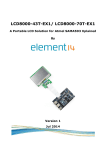
2. Block Diagrams
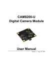
The figure shown below is a block diagram that shows how LCD-EX works when using
16-bit logic interface.
POWER
LCD_PWM
IIC
TP_BUSY
Controller
RIoT
LCD
SPI Touch INF
TP_INT
TP_SPI
interface
DISP0_DEN
DISP0_HSY
DISP0_VSY
DISP0_CLK
DB0 ~ DB15
Figure 1
Copyright © 2014 Embest Technology
16bit RGB
(565)
16-Bit Logic Interface
LCD-EX 140101 Quick Guide
Embest Technology
2
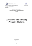
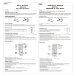
The figure shown below is a block diagram that shows how LCD-EX works when using
24-bit logic interface.
POWER
LCD_PWM
IIC
TP_BUSY
Controller
A5
A5
LCD
interface
SPI Touch INF
TP_INT
TP_SPI
DISP0_DEN
DISP0_HSY
DISP0_VSY
DISP0_DEN
DISP0_HSY
DISP0_VS
Figure 2
Y
Copyright © 2014 Embest Technology
24 bit RGB INF
24-Bit Logic Interface
LCD-EX 140101 Quick Guide
Embest Technology
3
Interfaces on LCD-EX
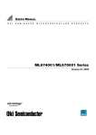
1. Locations and Types of Interfaces
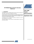
The following images shows locations of the interfaces on LCD-EX named J1, J2 and J13.
J1
1
2
3
4
J14
J15
J12
J11
321
321
321
321
J2
Figure 3
J1/J2 Interfaces
J13
Copyright © 2014 Embest Technology
LCD-EX 140101 Quick Guide
Embest Technology
4
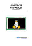
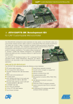
Figure 4
J13 Interface
The following table lists the brief descriptions of these interfaces.
Table 1
Interface Description
Names
Descriptions
J1
50-Pin interface for colored display
J2
24-bit RGB A5 interface
J13
16-bit 565
RIoT interface
J11
J12
SPI line module Select
J14
J15
2. Pin Definitions of Interfaces
The following tables contain detailed information about these interfaces.
Table 2
Pin Definitions of J1
Pins
Definitions
1
B0
Blue Data0
2
B1
Blue Data1
3
B2
Blue Data2
4
B3
Blue Data3
5
B4
Blue Data4
6
B5
Blue Data5
7
B6
Blue Data6
8
B7
Blue Data7
9
GND
10
G0
Green Data0
11
G1
Green Data1
12
G2
Green Data2
13
G3
Green Data3
14
G4
Green Data4
15
G5
Green Data5
16
G6
Green Data6
17
G7
Green Data7
18
GND
19
R0
Red Data0
20
R1
Red Data1
21
R2
Red Data2
Copyright © 2014 Embest Technology
Descriptions
GND
GND
LCD-EX 140101 Quick Guide
Embest Technology
5
Pins
Definitions
22
R3
Red Data3
23
R4
Red Data4
24
R5
Red Data5
25
R6
Red Data6
26
R7
Red Data7
27
GND
GND
28
DEN
Pixel data enable (TFT)
29
HSYNC
LCD Horizontal Synchronization
30
VSYNC
LCD Vertical Synchronization
31
GND
GND
32
CLK
LCD Pixel Clock
33
GND
GND
34
X+
X+ Position Input
35
x-
X- Position Input
36
Y+
Y+ Position Input
37
Y-
Y - Position Input
38
SPI_CLK
SPI serial clock
39
SPI_MOSI
SPI Master Output, Slave Input
40
SPI_MISO
SPI Master Input, Slave Output
41
SPI_CS
SPI Chip Select
42
IIC_CLK
IIC master serial clock
43
IIC_DAT
IIC serial bidirectional data
44
GND
GND
45
VDD1
3.3V
46
VDD2
3.3V
47
VDD3
5V
48
VDD3
5V
49
RESET
Reset
50
PWREN
Backlight enable
Table 3
Descriptions
Pin Definitions of J2
Pins
Definitions
1
GND
2
5V
VCC Input
3
5V
VCC Input
4
NC
NC
5
LCD_PWM
Backlight enable
6
TP_BUSY
Touch Pad Busy Signal
7
TP_INT
Touch Pad Interruput
8
I2C_CLK
IIC master serial clock
Copyright © 2014 Embest Technology
Descriptions
GND
LCD-EX 140101 Quick Guide
Embest Technology
6
9
I2C_DAT
GND
10
NC
VCC Input
11
CSPI_CLK
VCC Input
12
CSPI_MOSI
NC
13
CSPI_MISO
Backlight enable
14
TP_SPI_SCSn
15
DISP0_DEN
Touch Pad Interruput
16
DISP0_HSYNC
IIC master serial clock
17
DISP0_VSYNC
IIC serial bidirectional data
18
DISP0_CLK
19
GND
20
DISP0_DAT23
SPI Master Output, Slave Input
21
DISP0_DAT22
SPI Master Input, Slave Output
22
DISP0_DAT21
SPI Chip Select
23
DISP0_DAT20
Data enable (TFT)
24
GND
25
DISP0_DAT19
Touch Pad Busy Signal
NC
SPI serial clock
LCD Horizontal Synchronization
LCD Vertical Synchronization
26
DISP0_DAT18
DISP0_DAT18
27
DISP0_DAT17
DISP0_DAT17
28
DISP0_DAT16
DISP0_DAT16
29
GND
GND
30
DISP0_DAT15
DISP0_DAT15
31
DISP0_DAT14
DISP0_DAT14
32
DISP0_DAT13
DISP0_DAT13
33
DISP0_DAT12
DISP0_DAT12
34
GND
GND
35
DISP0_DAT11
DISP0_DAT11
36
DISP0_DAT10
DISP0_DAT10
37
DISP0_DAT9
DISP0_DAT9
38
DISP0_DAT8
DISP0_DAT8
39
GND
GND
40
DISP0_DAT7
DISP0_DAT7
41
DISP0_DAT6
DISP0_DAT6
42
DISP0_DAT5
DISP0_DAT5
43
DISP0_DAT4
DISP0_DAT4
44
GND
GND
45
DISP0_DAT3
DISP0_DAT3
46
DISP0_DAT2
DISP0_DAT2
47
DISP0_DAT1
DISP0_DAT1
48
DISP0_DAT0
DISP0_DAT0
49
GND
GND
50
ID_SYS
ID_SYS
Copyright © 2014 Embest Technology
LCD-EX 140101 Quick Guide
Embest Technology
Table 4
7
Pin Definitions of J13
Pins
Definitions
1
NC
2
5VIN
VCC Input
3
GND
GND
4
GND
GND
5
DISP0_CLK
LCD Pixel Clock
6
DISP0_DAT3
DISP0_DAT3
7
DISP0_DEN
Data enable (TFT)
8
DISP0_DAT4
DISP0_DAT4
9
DISP0_HSYNC
10
DISP0_DAT5
11
DISP0_VSYNC
12
DISP0_DAT6
DISP0_DAT6
13
DISP0_DAT7
DISP0_DAT7
14
DISP0_DAT23
DISP0_DAT23
15
DISP0_DAT15
DISP0_DAT15
16
NC
17
DISP0_DAT19
18
NC
19
DISP0_DAT20
20
TBD
21
DISP0_DAT21
22
TBD
23
DISP0_DAT22
24
TP_BUSY
25
DISP0_DAT10
26
TP_INT
27
DISP0_DAT11
28
CSPI_MOSI
29
DISP0_DAT12
30
CSPI_CLK
31
NC
32
TP_SPI_SCSn
33
NC
34
CSPI_MISO
35
I2C4_SCL
36
DISP0_DAT13
37
I2C4_SDA
38
DISP0_DAT14
39
GND
40
LCD_PWM
Copyright © 2014 Embest Technology
Descriptions
NC
Horizontal Synchronization
DISP0_DAT5
Vertical Synchronization
NC
DISP0_DAT19
NC
DISP0_DAT20
TBD
DISP0_DAT21
TBD
DISP0_DAT22
Touch Pad Busy Signal
DISP0_DAT10
Touch Pad Interruput
DISP0_DAT11
SPI Master Output, Slave Input
DISP0_DAT12
SPI Master Input, Slave Output
NC
DISP0_DAT6
NC
DISP0_DAT5
IIC master serial clock
DISP0_DAT13
IIC serial bidirectional data
DISP0_DAT14
GND
Backlight Enable
LCD-EX 140101 Quick Guide
Embest Technology
Table 5
module
Application
V1
SAMA5D3
Xplained
Version A
V2
SAMA5D3
Xplained
Version B
8
SPI
line module select
Jumper cap select
The SPI module of SAMA5D3
Xplained (J22)
J11
J12
J14
J15
PIN3------PIN2
PIN3------PIN2
PIN3------PIN2
PIN3------PIN2
PIN 37
PIN 38
PIN 39
PIN 40
=
=
=
=
SPI0_NPCS3
SPI0_MISO
SPI0_MOSI
SPI0_SPCK
J11
J12
J14
J15
PIN1------PIN2
PIN1------PIN2
PIN1------PIN2
PIN1------PIN2
PIN 37
PIN 38
PIN 39
PIN 40
=
=
=
=
SPI0_SPCK
SPI0_MOSI
SPI0_MISO
SPI0_NPCS3
Use of LCD-EX
Hereafter SAMA5D3 Xplained development board and a 4.3-inch LCD module will be
taken as the example devices working with LCD-EX.
Copyright © 2014 Embest Technology
LCD-EX 140101 Quick Guide
Embest Technology
9
Note:If use a 7-inch LCD module, it is recommended to use USB power supply, do not
use the computer USB power supply.
1. Configuring Kernel
1) Linux kernel includes lots of DTS files suited for different kinds of chips and
platforms. Let’s assuming a 4.3-inch LCD display is used and the configuration
file should be selected accordingly. (LCDs of different sizes need different DTS
files, but same configurations)
Table 6
configuration File for 4.3-inch LCD
cd linux-3.10.0
vim arch/arm/boot/dts/ at91-sama5d3_xplained_pda4.dts
ahb {
apb {
mmc0: mmc@f0000000 {
pinctrl-names = "default";
pinctrl-0
=
<&pinctrl_mmc0_clk_cmd_dat0
&pinctrl_mmc0_dat1_3
&pinctrl_mmc0_dat4_7 &pinctrl_mmc0_cd>;
status = "okay";
slot@0 {
reg = <0>;
bus-width = <8>;
cd-gpios = <&pioE 0 GPIO_ACTIVE_LOW>;
};
};
spi0: spi@f0004000 {
cs-gpios = <&pioD 13 0>, <&pioD 16 0>, <0>, <0>;
status = "okay";
ads7846: touchscreen@0 {
compatible = "ti,tsc2046";
reg = <1>;
spi-max-frequency = <1000000>;
pinctrl-names = "default";
pendown-gpio = <&pioE 7 0>;
irq = <&pioE 7 0>;
ti,settle-delay-usec = /bits/ 16 <150>;
ti,debounce-max = /bits/ 16 <10>;
ti,debounce-tol = /bits/ 16 <5>;
Copyright © 2014 Embest Technology
LCD-EX 140101 Quick Guide
Embest Technology
10
ti,debounce-rep = /bits/ 16 <1>;
ti,keep-vref-on = /bits/ 16 <1>;
ti,x-min = /bits/ 16 <0>;
ti,x-max = /bits/ 16 <8000>;
ti,y-min = /bits/ 16 <0>;
ti,y-max = /bits/ 16 <4800>;
ti,x-plate-ohms = /bits/ 16 <40>;
ti,pressure-max = /bits/ 16 <255>;
linux,wakeup;
status = "okay";
};
};
can0: can@f000c000 {
status = "okay";
};
The IRQ register information of mxt needs to be removed when connecting
resistive touch-screen, because the atmel_mxt_ts IRQ pin of the display would
be used by module driver too.
Table 7
Remove IRQ Register Information
vim arch/arm/boot/dts/at91-sama5d3_xplained_dm_pda4.dtsi
ahb {
apb {
i2c1: i2c@f0018000 {
qt1070: keyboard@1b {
compatible = "qt1070";
reg = <0x1b>;
interrupt-parent = <&pioE>;
interrupts = <8 0x0>;
pinctrl-names = "default";
pinctrl-0 = <&pinctrl_qt1070_irq>;
wakeup-source;
};
atmel_mxt_ts@4a {
compatible = "atmel,atmel_mxt_ts";
reg = <0x4a>;
/*
interrupt-parent = <&pioE>;
interrupts = <7 0x0>;
pinctrl-names = "default";
Copyright © 2014 Embest Technology
LCD-EX 140101 Quick Guide
Embest Technology
11
pinctrl-0 = <&pinctrl_mxt_ts>;
*/
status = "okay";
};
};
Configuring the kernel to include driver for TSC2045.
Table 8
Configuration of Driver
make ARCH=arm menuconfig
Device Drivers
--->
Input device support
[*]
Touchscreens
<*>
--->
--->
ADS7846/TSC2046/AD7873 and AD(S)7843 based touchscreens
Note:
The code marked in blue in these table are the parts that can be added or changed for
realizing different configurations.
2) Execute the following instructions to recompiling the kernel;
make ARCH=arm CROSS_COMPILE=arm-none-linux-gnueabi- dtbs
make ARCH=arm CROSS_COMPILE=arm-none-linux-gnueabi- uImage
3) The image files generated can be found under the following directories;
DTB image: arch/arm/boot/dts/at91-sama5d3_xplained_pda4.dtb
uImage: arch/arm/boot/uImage
Copyright © 2014 Embest Technology
LCD-EX 140101 Quick Guide
Embest Technology
12
2. Connections and Tests
1) Use two flat ribbon cables with pins on same side to connect the conversion
module, SAMA5D3 Xplained and LCD module together as shown below;
Figure 5
Hardware Connections
2) Connect the debugging serial interface of SAMA5D3 Xplained to PC and then
power on the development board;
3) Update the system with new uImage and at91-sama5d3_xplained_pda4.dtb, and
then reboot to enter Linux system;
4) Execute the following instruction to view the device node of touch-screen;
root@sama5d3_xplained:~# dmesg |grep -ir ads7846
The terminal window shows information as follows;
Table 9
Device Node Information
ads7846 spi0.1: touchscreen, irq 52
Copyright © 2014 Embest Technology
LCD-EX 140101 Quick Guide
Embest Technology
input:
ADS7846
13
Touchscreen
as
/devices/ahb.0/apb.1/f0004000.spi/spi_master/spi0/spi0.1/input/input0
The characters above marked in blue represent the device node.
Note:
input0 is associated to /dev/input/event0, input1 is associated to /dev/input/event1, and so
on.
5) Execute the following instruction to set environment variable for tslib;
root@sama5d3_xplained:~# export TSLIB_TSDEVICE=/dev/input/event0
6) Execute the following instruction to run a calibration on touch-screen;
root@sama5d3_xplained:~# ts_calibrate
7) Execute the following instruction to test touch-screen;
root@sama5d3_xplained:~# ts_test
Copyright © 2014 Embest Technology
LCD-EX 140101 Quick Guide
Embest Technology
14
Considerations
Please note the following considerations when connecting the hardware together:
1) If touch-screen is not precise as it should be after screen calibration, please
check the connection between the module and flat ribbon cable to ensure that
the 4 pins-for-touch of the interface on the module are correctly connected to the
pins of touch-screen, in other words, ensure the X pin of the module (or
touch-screen) is connected to the X pin of touch-screen (or the development
board);
2) There are two 50-pin PFC interfaces on the module named J1 and J2
respectively. J1 is a flip-lock connector used to connect LCDs; J2 is a slide-lock
connector used to connect controllers. LCD displays cannot work if being
connected to the wrong interface;
Copyright © 2014 Embest Technology
LCD-EX 140101 Quick Guide
Embest Technology
15
Technical Support and Warranty
Technical Support
Embest Technology provides its product with one-year free technical support
including:
Providing software and hardware resources related to the embedded products of
Embest Technology;
Helping customers properly compile and run the source code provided by
Embest Technology;
Providing technical support service if the embedded hardware products do not
function properly under the circumstances that customers operate according to
the instructions in the documents provided by Embest Technology;
Helping customers troubleshoot the products.
The following conditions will not be covered by our technical support service. We will
take appropriate measures accordingly:
Customers encounter issues related to software or hardware during their
development process;
Customers encounter issues caused by any unauthorized alter to the embedded
operating system;
Customers encounter issues related to their own applications;
Customers encounter issues caused by any unauthorized alter to the source
code provided by Embest Technology;
Warranty Conditions
1) 12-month free warranty on the PCB under normal conditions of use since the sales
of the product;
Copyright © 2014 Embest Technology
LCD-EX 140101 Quick Guide
Embest Technology
16
2) The following conditions are not covered by free services; Embest Technology will
charge accordingly:
Customers fail to provide valid purchase vouchers or the product identification
tag is damaged, unreadable, altered or inconsistent with the products.
Products are damaged caused by operations inconsistent with the user manual;
Products are damaged in appearance or function caused by natural disasters
(flood, fire, earthquake, lightning strike or typhoon) or natural aging of
components or other force majeure;
Products are damaged in appearance or function caused by power failure,
external forces, water, animals or foreign materials;
Products malfunction caused by disassembly or alter of components by
customers or, products disassembled or repaired by persons or organizations
unauthorized by Embest Technology, or altered in factory specifications, or
configured or expanded with the components that are not provided or recognized
by Embest Technology and the resulted damage in appearance or function;
Product failures caused by the software or system installed by customers or
inappropriate settings of software or computer viruses;
Products purchased from unauthorized sales;
Warranty (including verbal and written) that is not made by Embest Technology
and not included in the scope of our warranty should be fulfilled by the party who
committed. Embest Technology has no any responsibility;
3) Within the period of warranty, the freight for sending products from customers to
Embest Technology should be paid by customers; the freight from Embest to
customers should be paid by us. The freight in any direction occurs after warranty
period should be paid by customers.
4) Please contact technical support if there is any repair request.
Note:
Embest Technology will not take any responsibility on the products returned by anyone
without the permission of the company.
Copyright © 2014 Embest Technology
LCD-EX 140101 Quick Guide
Embest Technology
17
Contact Information
Technical Support
Telephone Number: +86-755-25635626-872/875/897
Email Address: [email protected]
Sales Information
Telephone Number: +86-755-25635626-860/861/862
Fax Number: +86-755-25616057
Email Address: [email protected]
Company Information
Company Website: http://www.armkits.com
Company Address: Tower B 4/F, Shanshui Building, Nanshan Yungu Innovation Industry
Park, Liuxian Ave. No. 1183, Nanshan District, Shenzhen, Guangdong, China (518055)
Copyright © 2014 Embest Technology
LCD-EX 140101 Quick Guide