1
Techwell,Inc.
e
e
h
a
D
.
w
U
4
t
m
o
.c
TW9906/TW9909 Evaluation Board User’s Manual
S
a
t
w
m
o
w
TW9906/TW9909
Evaluation Board
.c
U
User’s Manualt4
e
e
h
S
a
t
a
.D
w
(Rev 1.0)
w
w
Techwell, Inc.
408 Plumeria Drive
San Jose, CA 95134
URL http://www.techwellinc.com
U
4
t
m
o
.c
Disclaimer
This document provides technical information for the user. Techwell, Inc. reserves the right to modify the
information in this document as necessary. The customer should make sure that they have the most recent data
sheet version. Techwell Inc. holds no responsibility for any errors that may appear in this document. Customers
should take appropriate action to ensure their use of the products does not infringe upon any patents. Techwell
Inc. respects valid patent rights of third parties and does not infringe upon or assist others to infringe upon such
rights.
e
e
h
S
a
t
a
1
w
w
w
.DVersion 1.00
3/8/2005
Techwell,Inc.
TW9906/TW9909 Evaluation Board User’s Manual
1. Overview
TW9906 and TW9909 are high quality NTSC, PAL, and SECAM multi-standard video decoder plus
RGB mixing for multimedia applications. The TW9906/TW9909 evaluation board can demonstrate
most of the decoder’s features and allows easy evaluation of the TW9906, TW9909 performance.
Features such as Scaling and Cropping can be easily examined by modifying a few register setting,
switching input and output path can also be changed by a single click of the mouse. The
evaluation board is controlled via a RS-232 serial interface cable from a PC, and an application
software namely SerCon. User can also use a terminal emulator such as Hyper-terminal, all
registers can be manually modified. With TW9909, an OSD menu is also available, together with
on-board push buttons, changing register settings and other features without the need of a PC.
In order to truly explore the capability and performance of the TW9906/TW9909, user is strongly
recommended to use component output (from DAC, default setting).
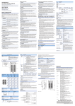
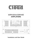
The main signal flow of the evaluation board is depicted below.
Input
connectors
Decoder
TW9906 or
TW9909
FPGA and
SDRAM
DAC or
Encoder
Output
connectors
2. TW9906_9 Evaluation Board Features
2.1. Input/output
On the board there are CVBS/S-video/Component/SCART input connectors connected to decoder
inputs and CVBS/S-Video/Component output connectors connected to the signals from DAC or
the encoder. Use JP3, JP4, JP5 to select the component outputs between DAC and the encoder.
Default output is from the DAC. CVBS/S-video output is always from the encoder.
INPUTS:
CVBS
S-VIDEO
Components (YPbPr)
SCART
CONNECTORS
CON1
CON4
Y/G:CON1, Pb/B:CON2, Pr/R:CON3
CON5
OUTPUTS:
CVBS
S-VIDEO
*Components (YPbPr or RGB)
CSYNC
CONNECTORS
CON13
CON12
Y/G: CON9, Pb/B: CON10, Pr/R:CON11
CON8
*Recommended feature for evaluation
2
Version 1.00 3/8/2005
Techwell,Inc.
TW9906/TW9909 Evaluation Board User’s Manual
2.2. Downscaling
With frame buffer memory turned on, user can see the scaled down image by adjusting
register 0x0D, 0x0E and 0x0F. Tips: by only adjusting 0x0E from the default of minimum
value of 0x11 to 0x22 or 0x33, the scaling effect can be seen immediately.
2.3. VIP (Video Interface Port), and Headers
Header JP1 signals are compatible to VIP standard. User can hook up JP1 to a VGA VIP
header with a flat cable (not included).
2.4. Closed-Caption
Closed-Caption is supported by Z86129.
2.5. LLC (Line-Locked Clock) / Free-run clock mode
In order to avoid output jitter when using Component output thru the DAC, user must turn on
the LLC function, and choose Direct Pass mode (turn off the Frame Buffering feature from the
board). To turn on LLC mode, Dip switch S1 position 4 must flip to off position (default).
Register 0x03 bit 5, LLCMODE set to 1. All above settings are default.
When use composite output thru encoder (CVBS or S-Video), user can Free-Run mode (LLC
off). In Free-Run clock mode, frame buffer must be turned on to remove the output jitter.
2.6. OSD (On Screen Display)
OSD feature is available only with TW9909. This feature can be activated by pressing the
menu buttons, and must set slide switch S12 accordingly to match input source.
2.7. Function of the on-board FPGA (U5)
As a SDRAM (frame buffer) controller, is mainly for providing buffering for decoder’s scaling
function as well as removing jitter when the board is in the Free-run clock mode.
As a format converter, the FPGA de-multiplex 10-bit, 27MHz clocked ITU-R656 4:2:2 data from
decoder into component Y,U,V and feed to triple 10-bit video DAC (U10 AD7123), the output
from DAC is component Y/Pr/Pb or R/G/B.
The FPGA interfaces to the Encoder in 10-bit mode. In bypass mode, data can feed through
the FPGA from decoder directly to encoder. It also generates other synchronous signal in
Free-run clock mode for frame buffered signal and to Encoder.
A 2-wire Serial interface is used for communication between Microcontroller and the FPGA.
LEDs are also controlled by the FPGA.
3
Version 1.00 3/8/2005
Techwell,Inc.
TW9906/TW9909 Evaluation Board User’s Manual
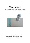
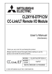
3. Input/output connectors Location
DAC/Encoder selector
VIP Header
Inputs
Outputs
CVBS / Y
CVBS/Y/G
S-Video
Pb / Blue
Pr / Red
Pr / Red
Y / Green
S-Video
Pb / Blue
CSync
SCART
RS-232
Power 9VDC
User Button
Dip-switch
4
Reset
LEDs
Version 1.00 3/8/2005
Techwell,Inc.
TW9906/TW9909 Evaluation Board User’s Manual
4. Power Adaptor
DC power adaptor is included in the kit, or use any 7~9V/1.5A DC adaptor with center + plug.
5. Dip-switch settings
There are board options user can set by the Dip-switches S1.
Switch Function description
1
2
3
4
5
6
7
8
Reserved
Reserved
Auto Register Set mode ON (default), some registers are changed
automatically by the Microcontroller, such as automatically detect video
input (color system, interlace, etc).
Manual mode: User controls all board function via RS232 Serial
Interface.
OFF: LLC(default), ON: Free-run clock, When using component output
video signal, must set LLC mode. Refer to LLC/Free-run section for
detail.
Reserved
FPGA programming loading M2
FPGA programming loading M1
FPGA programming loading M0
Default pos
OFF
OFF
OFF
ON
OFF
OFF
OFF or ON
OFF
ON
6. Slide Switch
Slide switch S12 is for OSD selection for CVBS/Component and SCART. This switch must set
accordingly to match the source of input for OSD to properly function.
5
Version 1.00 3/8/2005
Techwell,Inc.
TW9906/TW9909 Evaluation Board User’s Manual
7. Jumpers and Headers
Jumper
Function
JP1
JP2
JP3
JP4
JP5
JP6
JP7
JP8
JP9
JP10
JP11
JP12
JP13
JP14,15,16
JP17
JP18
VIP standard compatible output header
Power down (TW9906/TW9909 )
Pr Component output select from DAC or Encoder
Y Component output select from DAC or Encoder
Pb Component output select from DAC or Encoder
Select sync from FPGA or Decoder for VS
Select sync from FPGA or Decoder for HS
JTAG port for CPLD
Programming port
CPLD test header
Microcontroller test header
2-wire serial interface signal
Boot jumper for Microcontroller firmware download when jumped
Not applicable
Select sync from FPGA or Decoder for CSYNC
Audio Clock Signal
8. User Push Button
There are 8 push buttons on the evaluation board.
Button Name
S2
S3
*S4
*S5
S6
Function
RESET
MODE
DOWN
UP
SEL
System reset, reset the on-board 8051 Microcontroller
Short cut to Function Demo function (LLC, DAC, ENC)
Select or Enter the highlighted menu item in red
Move to upper menu
Input select: CVBS(default) -> S-Video -> component ->
SCART(TW9909) -> CVBS.
If being held down for >2s, LED T2 will be on indicating
Caption is on.
*S7
LEFT
Scroll down, decrement index or register address
*S8
MENU
Main Menu
*S9
RIGHT
Scroll up, increment index or register address
*Function only available in TW9909 with OSD feature for menu accessing.
6
Version 1.00 3/8/2005
Techwell,Inc.
TW9906/TW9909 Evaluation Board User’s Manual
9. Menu Map
The menu system is accessible through the 5 buttons stated in the User Push Button section.
The OSD feature for this menu system is only available in TW9909 and not available in TW9906.
On top of the 5 push buttons, there are 2 more short cut buttons that can immediately lead to the
frequently used functions such as Video inputs (S6) and Demo Functions (S3). All these push
buttons are functional on both TW9906 and TW9909, except that with TW9906, user has to shoot
in the dark when traversing the menu using these buttons.
Menu
Video In/Out…
Composite In
S-Video In
Component In
SCART In
S-Video Out
Component Out
S-Video Out
Register Set…
Decoder
Encoder
FPGA
Scaling…
Composite
Horizontal
Vertical
Function Demo…
Caption
ON
OFF
LLC Mode
ON
OFF
DAC Output Mode
Direct Pass
Frame Buffering
ENC Output Mode
Frame Buffering
Direct Pass
Reset…
Register Status
Register Status
Register Setting
Register Setting
ON
OFF
Help…
Escape
Button Name
Function
S8
S5
S4
S9
S7
Main Menu
Move to upper menu
Select or Enter the highlighted menu item in red
Scroll up, increment index or register address
Scroll down, decrement index or register address
MENU
UP
DOWN
RIGHT
LEFT
7
Version 1.00 3/8/2005
Techwell,Inc.
TW9906/TW9909 Evaluation Board User’s Manual
10. LEDs
Name
Function indicated when LED on
Power
Done
CPLD
T1
T2
T3
T4
Power on
FPGA loading fail
Reserved
PAL mode on
Caption mode on
Reserved
Reserved
11. How to control the TW9906_9 registers
Note: If the Auto Mode is on (position 3 of Dip Switch S1 is set to off), the on-board Microcontroller
continues checking the decoder status and changes registers when weak/bad signals occur such
as VCR Playing FF, Fast Rewind, noisy TV, etc. It also automatically detects color system. User
may want to turn off this function when manually changing registers. Turn ‘ON’ the Dip-switch3.
This will stop the auto compensation feature.
There are two ways to adjust the register of the TW9906 and TW9909 on the TW9906/TW9909
evaluation board. First method is using the on-board push buttons, second method is using a PC
via the RS232 serial port.
11.1. Using Push Buttons
When using push buttons, it is best with TW9909 where OSD feature is available. Even
though these buttons are functional under TW9906, due to lack of the OSD feature, it is hard for user
to control the board functions. Follow the menu map in previous section to traverse the menu item
and adjust the register content by using the Left (S7) and Right (S9) button, or use these 2 buttons to
scroll up and down among menu items. Use the Down (S4) button to enter lower level menu or
select the highlighted item (in red). Use Up (S5) button to move up one level from the current menu.
11.2. Using PC Serial port
When using a PC to control, there are 2 ways. First, user can use the HyperTerminal
command line style to control. Second, use the Serial Controller application which is a user
friendly application with Graphical User Interface (supplied by TechWell). Using PC to control
requires that a null-modem cable between PC serial port and the board serial port. The nullmodem cable is provided with the board.
8
Version 1.00 3/8/2005
Techwell,Inc.
TW9906/TW9909 Evaluation Board User’s Manual
11.2.1. Null Modem Cable
If a null-modem cable is not available, user can build one with the connections as follows.
9 PIN D-SUB FEMALE
9 PIN D-SUB FEMALE.
Receive Data [2]
[3] Transmit Data
Transmit Data [3]
[2] Receive Data
Data Terminal Ready [4]
[6]+[1] Data Set Ready + Carrier Detect
System Ground [5]
[5] System Ground
Data Set Ready + Carrier Detect [6]+[1]
[4] Data Terminal Ready
Request to Send [7]
[8] Clear to Send
Clear to Send [8]
[7] Request to Send
Null Modem Cable from PC
Serial Port connected to here.
9
Version 1.00 3/8/2005
Techwell,Inc.
TW9906/TW9909 Evaluation Board User’s Manual
11.2.2. Set up and Use the Hyper Terminal to Control the Board
Follow these steps to create a Hyper Terminal control short cut
Select “Hyper Terminal”
Connection Description
10
Version 1.00 3/8/2005
Techwell,Inc.
TW9906/TW9909 Evaluation Board User’s Manual
Choose COM port.
Set the COM port properties. Those should be 57600bps, 8 data, No parity, 1 stop, No
flow control.
11
Version 1.00 3/8/2005
Techwell,Inc.
TW9906/TW9909 Evaluation Board User’s Manual
Set line delay :10~30ms,
Note: if there is check sum error during firmware download, user may need to adjust this
value.
Character delay:0ms. Select [File\Properties\Settings\ASCII Setup..\]. It is required when
user download new firmware.
Type [Enter] and see if it works.
The command prompt will be displayed.
[88]>
12
Version 1.00 3/8/2005
Techwell,Inc.
TW9906/TW9909 Evaluation Board User’s Manual
11.2.2.1.
Basic Command Set and Control Example via the Hyper Terminal
Type H or ? at the command prompt will display the available command set.
Examples.
Change address
[88]>C 28
Address : 28
[28]>
Dump registers
[88]>d 0
Read [Adrs:88h,00h] 50h
Read [Adrs:88h,01h] 93h
Read [Adrs:88h,02h] 41h
Read [Adrs:88h,03h] A2h
Read [Adrs:88h,04h] 00h
Read [Adrs:88h,05h] 81h
Read [Adrs:88h,06h] 00h
Read [Adrs:88h,07h] 12h
[88]>
Read register
[88]>r 2
Read [Adrs:88h,02h] 68h
[88]>
Write register
[88]>w 2 41
Write 41h to [Adrs(88h)Index(02h)]
Read [Adrs:88h,02h] 41h
[88]>
13
Version 1.00 3/8/2005
Techwell,Inc.
TW9906/TW9909 Evaluation Board User’s Manual
Changing 2 wire serial bus slave device address.
TW9906, 09: 0x88
Z89129 : 0x28
ADV9174 : 0x54
// User can change the address to 0x8A, by swap R39, R40 resisters
Example
[88]>C 54
[54]>
// change slave address to ADV9174
// Now user can access registers in ADV9174
How to test the down-scaling.
To evaluate down-scaling performance, just change scaling registers(0x0d, 0x0e, 0x0f).
Example)
[88]>W e 22
// 1/4 size
[88]>W e 33
// 1/9 size
[88]>W e 44
// 1/16 size
[88]>W e 11
// full size
11.2.2.2.
Down Load new Firmware to TW9906/TW9909
Warning: This procedure could erase the firmware, if not handle correctly, the board will
not work.
Connect serial cable to host PC, and start Hyper Terminal.
Make sure Hyper Terminal settings are:
COM port properties: 57600bps, 8 data, No parity, 1 stop, No flow control.
Line delay : 30~10ms, Character delay : 0ms
Put a jumper at J13 next to reset push button.
loader screen will show up.
Power On or Press {Reset}.
The boot
Type ‘Y’, the following message will be seen,
14
Version 1.00 3/8/2005
Techwell,Inc.
TW9906/TW9909 Evaluation Board User’s Manual
Click Hyper Terminal menu [Transfer\Send Text File..]
Select the HEX file to be downloaded. Click Open Button and downloading will begin.
15
Version 1.00 3/8/2005
Techwell,Inc.
TW9906/TW9909 Evaluation Board User’s Manual
Firmware is being downloaded
Programming completed.
Follow the on screen instruction, and recycle the board power, then the board will run with
new firmware.
11.2.3. Install and Use the Serial Control application
11.2.3.1.
Install the Serial Control application
16
Version 1.00 3/8/2005
Techwell,Inc.
TW9906/TW9909 Evaluation Board User’s Manual
The SerCon application can be downloaded from the Techwell Website. Download the
application software in a compressed file SerCon170.zip. Unzip it to a local folder and
install it. During the installation, if it asks for the serial number, user can type in 000.
After installation is done, the following icon will be found under the program application.
User can copy the short cut to the desk top. Following is the icon.
Sercon.lnk
Detail instruction on how to use the SerCon, please refer to document “Instruction of Serial
Controller1216.pdf.”
The SerCon program also has command line input option for those who prefer using
command line input. This can be done by typing in the command in the command box in the
bottom of the SerCon GUI.
11.2.3.2.
Use SerCon to control registers and board features.
Turn on the power of the board, plug in the serial cable, and make sure JP13 is open.
Execute the SerCon program, the following will display.
17
Version 1.00 3/8/2005
Techwell,Inc.
TW9906/TW9909 Evaluation Board User’s Manual
Select device TW9906 or TW9909 from the device box, and check the box before the word
Display (right under P2). Click on P1, P2 and P1 again. The following screen will be seen
with current register content.
Hit the Reset button, pay attention to the Message Viewer, there are message scroll up
quickly.
Now user can change any register content and will see the resulting effect in real time.
Example 1: Scaling: change the content of Register 0Eh, from 11 to 22, the screen will be
scaled downed.
Example 2: Change Brightness. Register 10h, change content to 7F maximum brightness, or
80 to minimum.
User can explore other register following the datasheet.
Note that when placing the mouse cursor over the register in the SerCon graphical interface,
the name of that register will pop up.
18
Version 1.00 3/8/2005
Techwell,Inc.
TW9906/TW9909 Evaluation Board User’s Manual
Some frequently used features can be changed quickly by using the test menu.
Click on T6 from the menu bar (for TW9906 and 09)
The test menu will show up. User can click on the radio button to change the board features
such as decoder mode, encoder mode, LLC, DAC output mode, RTC mode, Progressive
mode, etc.
19
Version 1.00 3/8/2005
Techwell,Inc.
TW9906/TW9909 Evaluation Board User’s Manual
11.2.3.3.
Down Load Firmware to on board Microcontroller
Make sure JP13 boot jumper is short,
and Display ON is checked.
Push Reset button.
Type ‘Y’ in the Command box after received message from the message viewer.
When the erase is done the following screen will disply.
Click on “Send” button from the menu bar
20
Version 1.00 3/8/2005
Techwell,Inc.
TW9906/TW9909 Evaluation Board User’s Manual
Click on “Browse” and select the hex file to be down loaded.
Select the newest hex file, and click open, the download will begin.
Down Load In progress.
21
Version 1.00 3/8/2005
Techwell,Inc.
TW9906/TW9909 Evaluation Board User’s Manual
Download completed, click OK, remove JP13 jumper, and recycle the power.
11.2.3.4.
Down Load Firmware to on board FPGA
Set dip switch S1 pos 6, 7 and 8 respectively M2, M1, M0 to OFF.
Recycle the power.
Click “Flie Add” from menu tool bar.
22
Version 1.00 3/8/2005
Techwell,Inc.
TW9906/TW9909 Evaluation Board User’s Manual
Click on “Browse” from the File Merger and Loader window.
Choose “bit” file from open window.
23
Version 1.00 3/8/2005
Techwell,Inc.
TW9906/TW9909 Evaluation Board User’s Manual
Downloading in progress
The ending screen is shown as follow
Set dip switch pos 6, 7, 8 back to ON OFF ON or OFF OFF ON respectively.
Recycle the power, the board’s FPGA firmware is updated.
12. Revision History
Version
0
1.0
Date
01/21/2005
3/08/2005
Revision history
Initial release
Update and add details.
24
By
Brian An
Albert Au
Version 1.00 3/8/2005