1
MITSUBISHI ELECTRIC
MELSEC System Q
Programmable Logic Controllers
User's Manual
DeviceNet Master-Slave Module
QJ71DN91
GX Configurator-DN
Art. no.: 139835
01 05 2003
SSH (NA)-080143
Version F
MITSUBISHI ELECTRIC
INDUSTRIAL AUTOMATION
• SAFETY PRECAUTIONS •
(Always read these instructions before using this equipment.)
Before using this product, please read this manual and the relevant manuals introduced in this manual
carefully and pay full attention to safety to handle the product correctly.
The instructions given in this manual are concerned with this product. For the safety instructions of the
programmable controller system, please read the User's Manual of the CPU module to use.
In this manual, the safety instructions are ranked as "DANGER" and "CAUTION".
DANGER
Indicates that incorrect handling may cause hazardous conditions,
resulting in death or severe injury.
! CAUTION
Indicates that incorrect handling may cause hazardous conditions,
resulting in medium or slight personal injury or physical damage.
!
Note that the ! CAUTION level may lead to a serious consequence according to the circumstances.
Always follow the instructions of both levels because they are important to personal safety.
Please save this manual to make it accessible when required and always forward it to the end user.
[DESIGN PRECAUTIONS]
!
DANGER
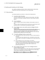
• If a communications error occurs to a device network, the node in such a communications error
will be in a state as follows:
(1) The master node (QJ71DN91) maintains input data which had been received from the slave
node before the error occurred.
(2) Whether the slave node's output signal is turned off or maintained is determined by the
slave node's specifications or the parameters set at the master node. When using
QJ71DN91 as a slave node, the entered data from master node before the faulty node is
maintained.
By referring to communications states of the slave node, arrange an interlock circuit in a
sequential program and provide safety mechanism externally of the slave node in order the
system to operate safely.
!
CAUTION
• Do not bunch the control wires or communication cables with the main circuit or power wires, or
install them close to each other.
They should be installed 300 mm (11.8 inch) or more from each other. Not doing so could result
in noise that may cause malfunction.
A-1
A-1
[INSTALLATION PRECAUTIONS]
!
CAUTION
• Use the PLC in an environment that meets the general specifications contained in the CPU
User's Manual to use.
Using this PLC in an environment outside the range of the general specifications may cause
electric shock, fire, malfunction, and damage to or deterioration of the product.
• When installing the module, securely insert the module fixing tabs into the mounting holes of the
base module while pressing the installation lever located at the bottom of the module downward.
Improper installation may result in malfunction, breakdown or dropping out of the module.
Securely fix the module with screws if it is subject to vibration during use.
• Tighten the screws within the range of specified torque.
If the screws are loose, it may cause fallout, short circuits, or malfunction.
If the screws are tightened too much, it may cause damage to the screw and /or the module,
resulting in fallout, short circuits or malfunction.
• Switch all phases of the external power supply off when mounting or removing the module.
Not doing so may cause electric shock or damage to the module.
• Do not directly touch the conductive area or electric components of the module.
Doing so may cause malfunction or failure in the module.
[WIRING PRECAUTIONS]
!
DANGER
• Make sure to shut off all the phases of the external power supply before starting installation or
wiring. Otherwise, the personnel may be subjected to an electric shock or the product to a
damage.
!
CAUTION
• Be careful not to let foreign matters such as sawdust or wire chips get inside the module.
These may cause fires, failure or malfunction.
• The top surface of the module is covered with protective film to prevent foreign objects such as
cable offcuts from entering the module when wiring.
Do not remove this film until the wiring is complete.
Before operating the system, be sure to remove the film to provide adequate heat ventilation.
• Be sure to fix cables leading from the module by placing them in the duct or clamping them.
Unless the cables are placed with a duct or clamped, the module or cables could be broken by
swinging or moving of the cables or unintentional pulling to cause an operation error resulting
from a contact error.
• Do not pull cables by holding them with a hand for removing the cables that are connected to the
module. To remove a cable having a connector, hold the connector connected to the module
with a hand. To remove a cable not having a connector, loosen the screws fastening to connect
the module. The cables being pulled while they are still connected to the module could break the
module or cables, or cause an operation error resulting from a contact error.
A-2
A-2
[CAUTIONS ON STARTUP AND MAINTENANCE]
!
DANGER
• Always turn off all external power supply phases before touching any terminals.
Failure to do this may result in malfunction.
• Always turn of all external power supply phases before cleaning or tightening the terminal
screws.
Failure to do this may result in malfunction.
• Do not disassemble or modify any module.
This will cause failure, malfunction, injuries, or fire.
• Always turn off all external power supply phases before mounting or dismounting the module.
Failure to do this may result in malfunction or damage to the module.
• Always make sure to touch the grounded metal to discharge the electricity charged in the body,
etc., before touching the module.
Failure to do so may cause a failure or malfunctions of the module.
[DISPOSAL PRECATION]
!
CAUTION
• Dispose of this product as industrial waste.
A-3
A-3
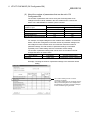
REVISIONS
The manual number is given on the bottom left of the back cover.
Print Date
Dec., 2000
Jun., 2001
Manual Number
SH (NA)-080143-A First Printing
SH (NA)-080143-B Addition
Section 2.3, 2.4
Revision
Delete
Section 2.2.1, 2.2.2
Correction
SAFETY PRECAUTIONS, About the Generic Terms and Abbreviations,
Product Configuration, Section 2.2, 2.4, Section 6.2, 6.2.1, 6.2.2, 6.3.3,
6.5
Feb., 2002
SH (NA)-080143-C
Correction
About the Generic Terms and Abbreviations, Section 2.2, Section 6.2.1,
6.2.2
Dec., 2002
SH (NA)-080143-D
Addition
Section 2.5
Correction
Section 2.2, Section 3.3.2, 3.4.1, Section 6.1, 6.2.1, 6.3.2, 6.4, 6.5,
Section 9.2.1, 9.2.2
Feb., 2003
SH (NA)-080143-E
Correction
SAFETY PRECAUTIONS, INTRODUCTION, CONTENTS, Section 6.2.2,
Section 6.3.3, Section 6.4, Section 6.5
May., 2003
SH (NA)-080143-F
Correction
Section 6.3.1
Japanese Manual Version SH-080125-F
This manual confers no industrial property rights or any rights of any other kind, nor does it confer any patent
licenses. Mitsubishi Electric Corporation cannot be held responsible for any problems involving industrial property
rights which may occur as a result of using the contents noted in this manual.
2000 MITSUBISHI ELECTRIC CORPORATION
A-4
A-4
INTRODUCTION
Thank you for purchasing the MELSEC-Q series PLC.
Before using the equipment. please read this manual carefully to develop full familiarity with the functions
and performance of the Q series PLC you have purchased, so as to ensure correct use.
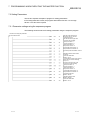
CONTENTS
SAFETY PRECAUTIONS..............................................................................................................................AREVISIONS ....................................................................................................................................................AINTRODUCTION............................................................................................................................................ACONTENTS....................................................................................................................................................AConformation to the EMC Directive and Low Voltage Instruction ................................................................AAbout the Generic Terms and Abbreviations ................................................................................................AProduct Configuration ....................................................................................................................................A1 OVERVIEW
1
4
5
5
8
8
9
1- 1 to 1- 2
1.1 Features ................................................................................................................................................... 1- 1
2 SYSTEM CONFIGURATION
2- 1 to 2- 6
2.1 Overall Configuration ............................................................................................................................... 22.2 Applicable Systems.................................................................................................................................. 22.3 How to Check the Function Version, Serial No. and Software Version ................................................. 22.4 About Use of the QJ71DN91 with the Q00J/Q00/Q01CPU ................................................................... 22.5 About Additional Function........................................................................................................................ 22.6 Compatible DeviceNet Products from Other Manufacturers .................................................................. 23 SPECIFICATIONS
1
3
4
5
6
6
3- 1 to 3- 51
3.1 Performance Specifications ..................................................................................................................... 3- 1
3.1.1 Maximum transmitting distance when thick and thin cables coexist ............................................... 3- 1
3.2 Functions .................................................................................................................................................. 3- 2
3.2.1 Master function (I/O communication function).................................................................................. 3- 2
3.2.2 Master function (Message communication function) ....................................................................... 3- 8
3.2.3 Slave function (I/O communication function).................................................................................... 3-11
3.3 I/O Signals for the PLC CPU ................................................................................................................... 3-13
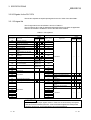
3.3.1 I/O signal list ...................................................................................................................................... 3-13
3.3.2 Details of the I/O signals ................................................................................................................... 3-14
3.4 Buffer Memory.......................................................................................................................................... 3-24
3.4.1 Buffer memory list ............................................................................................................................. 3-24
3.4.2 Buffer memory details ....................................................................................................................... 3-26
3.5 Communication Performance .................................................................................................................. 3-50
3.5.1 Scan time........................................................................................................................................... 3-50
3.5.2 Communication cycle ........................................................................................................................ 3-51
3.5.3 Transmission delays ......................................................................................................................... 3-51
A-5
A-5
4 SETUP AND PROCEDURES BEFORE OPERATION
4- 1 to 4- 14
4.1 Setup and Procedures before Operation ................................................................................................ 4- 1
4.1.1 When using the master function ....................................................................................................... 4- 1
4.1.2 When using the slave function.......................................................................................................... 4- 2
4.1.3 When using both the master function and slave function ................................................................ 4- 3
4.2 Loading and Installation ........................................................................................................................... 4- 4
4.2.1 Handling precautions ........................................................................................................................ 4- 4
4.2.2 Installation environment .................................................................................................................... 4- 4
4.3 Component Names and Settings ............................................................................................................ 4- 5
4.3.1 Meanings of the LED displays .......................................................................................................... 4- 6
4.3.2 Node number setting switch.............................................................................................................. 4- 7
4.3.3 Mode switch....................................................................................................................................... 4- 7
4.4 Hardware Test.......................................................................................................................................... 4- 8
4.5 Connecting the Communication Cables to the QJ71DN91 .................................................................... 4- 9
4.6 Communication Test ............................................................................................................................... 4- 10
4.7 Instructions for Connecting the Network Power Supply ........................................................................ 4- 11
4.7.1 Network power supply unit installation position............................................................................... 4- 11
4.7.2 Calculating network power supply unit installation position and current capacity.......................... 4- 12
5 PARAMETER SETTINGS
5- 1 to 5- 6
5.1 Description of Parameter Settings........................................................................................................... 55.1.1 Parameters for the master function .................................................................................................. 55.1.2 Parameters for the slave function..................................................................................................... 55.1.3 Common parameters for the master/slave functions ....................................................................... 55.2 Setting Using the Sequence Program..................................................................................................... 55.3 Setting Using the Auto Configuration Function ....................................................................................... 56 UTILITY PACKAGE (GX Configurator-DN)
1
1
2
2
2
3
6- 1 to 6- 21
6.1 Functions of the Utility Package .............................................................................................................. 6- 1
6.2 Installing and Uninstalling the Utility Package......................................................................................... 6- 2
6.2.1 User precautions ............................................................................................................................... 6- 2
6.2.2 Operating environment...................................................................................................................... 6- 4
6.3 Explanation of Utility Package Operation................................................................................................ 6- 5
6.3.1 How to perform common utility package operations........................................................................ 6- 5
6.3.2 Overview of operation ....................................................................................................................... 6- 8
6.3.3 Starting the intelligent function module utility .................................................................................. 6- 10
6.4 Auto Refresh Settings ............................................................................................................................. 6- 12
6.5 Monitor/Test ............................................................................................................................................ 6- 14
6.6 Flash ROM Settings................................................................................................................................ 6- 20
A-6
A-6
7 PROGRAMMING WHEN EXECUTING THE MASTER FUNCTION
7- 1 to 7- 12
7.1 Precautions on Programming .................................................................................................................. 7- 1
7.2 System Configuration............................................................................................................................... 7- 2
7.3 Setting Parameters .................................................................................................................................. 7- 4
7.3.1 Parameter settings using the sequence program ............................................................................ 7- 4
7.3.2 Creating parameters using auto configuration ................................................................................. 7- 6
7.3.3 Saving parameters in flash ROM...................................................................................................... 7- 6
7.4 I/O Communication with Slave Nodes..................................................................................................... 7- 7
7.5 Performing Message Communication ..................................................................................................... 7- 8
7.5.1 Example of message communication read ...................................................................................... 7- 8
7.5.2 Example of message communication write...................................................................................... 7- 9
7.6 Obtaining Error Information .................................................................................................................... 7- 10
7.7 Allocating Transmission/Reception Data Storage Devices for Future Expansion................................ 7- 11
8 PROGRAMMING WHEN EXECUTING THE SLAVE FUNCTION
8- 1 to 8- 4
8.1 System Configuration............................................................................................................................... 88.2 Setting Parameters Using the Sequence Program................................................................................. 88.3 I/O Communication with the Master Node .............................................................................................. 88.4 Obtaining Error Information ..................................................................................................................... 89 TROUBLESHOOTING
1
2
3
4
9- 1 to 9- 12
9.1 Items to Check When an Error Occurs ................................................................................................... 9- 2
9.1.1 Checking the LEDs ........................................................................................................................... 9- 2
9.1.2 When communication with all slave nodes cannot be performed (using the master function) ...... 9- 3
9.1.3 When communication with a specific slave node cannot be performed
(using the master function)................................................................................................................ 9- 4
9.1.4 When communication with the master node cannot be performed (using the slave function)....... 9- 5
9.2 Error Codes .............................................................................................................................................. 9- 6
9.2.1 Communication error codes.............................................................................................................. 9- 6
9.2.2 Execution error codes of message communication (using the master function only) .................... 9- 9
9.3 Verifying the QJ71DN91 Status on the GX Developer System Monitor ............................................... 9- 11
APPENDIX
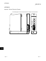
App- 1 to App- 7
Appendix 1 External Dimension Diagram .................................................................................................AppAppendix 2 Differences between the QJ71DN91 and the AJ71DN91/A1SJ71DN91 .............................AppAppendix 3 Parameter Setting Sheet (For the Master Function) .............................................................AppAppendix 4 Parameter Setting Sheet (For the Slave Function) ...............................................................AppAppendix 5 List of Communication Parameters of Slave Nodes Manufactured by Various
Manufacturers .........................................................................................................................AppAppendix 6 EDS File of the QJ71DN91 ....................................................................................................AppINDEX
A-7
1
2
3
4
5
6
Index- 1 to Index- 2
A-7
Conformation to the EMC Directive and Low Voltage Instruction
For details on making Mitsubishi PLC conform to the EMC directive and low voltage instruction when
installing it in your product, please see Chapter 3, "EMC Directive and Low Voltage Instruction" of the User's
Manual (Hardware) of the PLC CPU to use.
The CE logo is printed on the rating plate on the main body of the PLC that conforms to the EMC directive
and low voltage instruction.
BY making this product conform to the EMC directive and low voltage instruction, it is not necessary to make
those steps individually.
About the Generic Terms and Abbreviations
Unless otherwise specified, this manual uses the following generic terms and abbreviations to explain
QJ71DN91 DeviceNet Master·Slave Module.
Generic Term/Abbreviation
GX Developer
QCPU (Q mode)
GX Configurator-DN
QJ71DN91
Personal computer
A-8
Description
Generic product name of the product types SWnD5C-GPPW-E, SWnD5C-GPPW-EA,
SWnD5C-GPPW-EV and SWnD5C-GPPW-EVA.
"n" in the model is 4 or greater.
Generic term for Q00JCPU, Q00CPU, Q01CPU, Q02CPU, Q02HCPU, Q06HCPU,
Q12HCPU, Q25HCPU, Q12PHCPU, Q25PHCPU
Abbreviation for DeviceNet Master-Slave Module setting/Monitor Tool GX
Configurator-DN (SW1D5C-QDNU-E)
Abbreviation for QJ71DN91 DeviceNet Master-Slave Module
®
IBM PC/AT or compatible computer with DOS/V.
A-8
Product Configuration
The following is a list of the components in this product configuration.
Model name
QJ71DN91
SW1D5C-QDNU-E
SW1D5C-QDNU-EA
A-9
Product name
QJ71DN91 DeviceNet master-slave module
Terminal resistor 121Ω, 1/4W
Connector
GX Configurator-DN Version 1 (1-license product)
GX Configurator-DN Version 1 (Multiple-license product)
Quantity
(CD-ROM)
(CD-ROM)
1
2
1
1
1
A-9
1 OVERVIEW
MELSEC-Q
1 OVERVIEW
1
This manual explains the specifications and name of each component of the
QJ71DN91 DeviceNet master/slave module, which is used in combination with the
MELSEC-Q Series PLC CPU.
Please see DeviceNet Specification Manual (Release 2.0), Volumes 1 and 2, for the
specifications of DeviceNet.
DeviceNet is a registered trademark of Open DeviceNet Vendor Association, Inc.
POINT
Most of the DeviceNet products on the market are assumed to be compatible.
However, compatibility with the products of other manufacturers is not guaranteed.
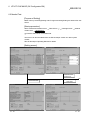
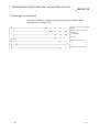
1.1 Features
This section explains the features of the QJ71DN91.
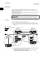
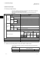
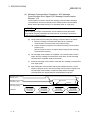
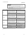
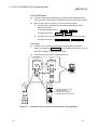
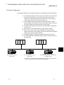
(1) The module conforms to the DeviceNet Specifications Manual (Release 2.0).
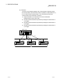
(2) The module can function as a master node, slave node, or master/slave node of
DeviceNet.
Master station Slave side
M
S
I/O communication between the master station and slave station is possible.
Communication is not possible.
: DeviceNet slave
QJ71DN91
master + slave
(Node No. 6)
QJ71DN91
master
(Node No. 5)
S
M
M
M
S
(Node No. 2)
S
(Node No. 7)
Master made by
other manufacturer
(Node No. 10)
24V power
supply
S
M
QJ71DN91 slave
(Node No. 3)
S
S (Node No. 8)
S
(Node No. 4)
QJ71DN91
slave
(Node No. 9)
S
QJ71DN91 slave
(Node No. 1)
(3) The parameters of QJ71DN91 can be set by any of the following three methods:
• Setting the parameters using GX Configurator-DN
• Setting the parameters using the TO instruction of a sequence program
• Setting the parameters using auto configuration
1-1
1-1
1 OVERVIEW
MELSEC-Q
(4) When the module functions as a master node of DeviceNet, I/O communication
and message communication with a DeviceNet slave node are possible.
(5) When the module functions as a master node of DeviceNet, the module can
communicate with a maximum of 63 slave nodes.
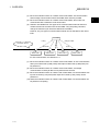
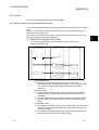
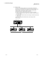
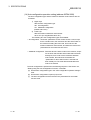
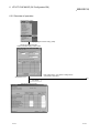
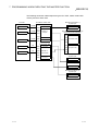
(6) Selection is available from four types of I/O communication methods when this
module functions as a master node in DeviceNet. They are polling, bit strobe,
change-of-state and cyclic which are defined in DeviceNet.
However, only one type of communication method can be selected for each slave
node.
QJ71DN91
Polling
Change-of-state
DeviceNet network
Bit strobe
Slave node 1
Slave node 2
Cyclic
Slave node 3
Slave node 4
For I/O communication, see Section 3.2.1.
(7) When the module functions as a master node of DeviceNet, an I/O communication
with input of 256 words (4,096 points) and output of 256 words (4,096 points) can
be performed.
(8) When the module functions as a master node of DeviceNet, a message
communication of 240 byte data can be performed at one time.
(9) When the module functions as a slave node of DeviceNet, I/O communication with
input of 64 words (1,024 points) and output of 64 words (1,024 points) can be
performed.
(10) When the module functions as a slave node of DeviceNet, I/O communication can
be performed via polling.
1-2
1-2
1
2 SYSTEM CONFIGURATION
MELSEC-Q
2 SYSTEM CONFIGURATION
This chapter explains the system configuration of DeviceNet.
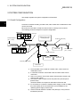
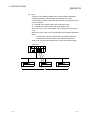
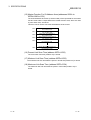
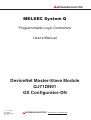
2.1 Overall Configuration
2
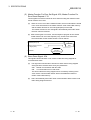
A total of 64 modules including a master node, slave nodes and a master/slave node
can be connected.
Each node is connected via a tap from the trunk line or directly to the trunk line.
The following shows an example of a system configuration:
Master node
Drop line
Network power-supply
module (24V DC)
Terminal resistor
(121Ω, 1/4W)
Trunk line (main line)
Slave node
Slave node
Terminal resistor
(121Ω, 1/4W)
Power supply tap
Tap
Slave node
Slave node
Drop line (branch line)
Slave node
1) The QJ71DN91 can be used as a master node, a slave node or a
master/slave node.
2) A combined maximum of 64 master node and slave nodes can be
connected.
3) There is no need to connect the master node and slave nodes in the
order of node number.
4) The network cable consists of trunk line (main line) and drop lines
(branch lines).
Terminal resistors are required on both sides of the trunk line.
5) It is necessary to connect the network power supply in order to supply
the power supply to the communication circuit in addition to the
operating power supply of each node.
6) Use the terminal resistors included in the package, or they must be
furnished by the user.
2-1
2-1
2 SYSTEM CONFIGURATION
MELSEC-Q
(1) Network specification
The following explains the network specifications of DeviceNet that uses the
QJ71DN91.
(a) Communication speed
The communication speed can be selected from 125kbaud, 250kbaud, or
500kbaud using the mode switch of the QJ71DN91.
The maximum cable length varies depending on the communication speed.
See Section 3.1, "Performance Specifications" for details.
(b) Supplying power to the network
The following describes the method of supplying network power to each
node:
1) Connect a dedicated power supply tap to the trunk-line cable and install
the network power-supply module.
2) The power is supplied from the network power-supply module to each
node via the network cable.
Remarks
Inquire to ODVA about the following devices required to construct a DeviceNet
network.
• Network power-supply module
• Power supply tap
• Tap
• Terminal resistor
• Network cable
Contact at ODVA is as follows:
Open DeviceNet Vendor Association, Inc.
Address
20423 State Road 7 - Suite 499 - Boca Raton, FL 33498 U.S.A.
TEL. +1-954-340-5412
FAX. +1-954-340-5413 or +1-561-477-6621
2-2
2-2
2
2 SYSTEM CONFIGURATION
MELSEC-Q
2.2 Applicable Systems
This section describes the system configuration for the QJ71DN91.
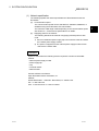
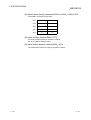
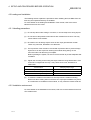
(1) Applicable module and the number of modules that can be installed
The following are the CPU module in which the QJ71DN91 can be installed and
the number of modules that can be installed.
Applicable module
CPU module
Number of modules that
can be installed
Q00JCPU
Maximum 16
Q00CPU
Q01CPU
Maximum 24
Q02CPU
Q02HCPU
Q06HCPU
Q12HCPU
Q25HCPU
Maximum 64
Q12PHCPU
Q25PHCPU
Maximum 64
Remarks
( 1)
Can be installed in Q mode only
( 1)
( 1)
1 See User's Manual (Function Explanation, Program Fundamentals) for the CPU module to use.
(2) Base unit in which the conversion module can be installed
The QJ71DN91 can be installed in any I/O slot ( 2) of the base unit. However, a
power shortage may occur depending on the combination with other installed
modules and the number of modules used, so always take into consideration the
power supply capacity when installing modules.
2 Limited to the range of the number of I/O points in the CPU module.
(3) Compatibility with a multiple PLC system
First read the QCPU (Q mode) (Function Explanation, Program Fundamentals)
User's Manual if the QJ71DN91 is used with a multiple PLC system.
(a) Compatible QJ71DN91
Use a QJ71DN91 with function version B or higher if using the module in a
multiple PLC system.
(b) Intelligent function module parameters
Perform PLC write of the intelligent function module parameters to the
control PLC of the QJ71DN91 only.
2-3
2-3
2 SYSTEM CONFIGURATION
MELSEC-Q
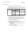
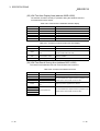
(4) Software packages supported
Correspondence between systems which use QJ71DN91s and software
packages are as shown below.
The GX Developer is necessary when using a QJ71DN91.
Software Version
GX Developer
Q00J/Q00/
Q01CPU
Q02/Q02H/
Q06H/Q12H/
Q25HCPU
Q12PH/
Q25PHCPU
GX Configurator-DN
2
Single PLC system
Version 7 or later
Multiple PLC system
Version 8 or later
Single PLC system
Version 4 or later
Version 1.00A or later
Multiple PLC system
Version 6 or later
Version 1.10B or later
Version 7.10L or later
Version 1.13P or later
Version 1.10L or later
Single PLC system
Multiple PLC system
2 Version 1.14Q or earlier is incompatible with Each Node Communication Error Status
(addresses 1C0H to 1C3H/448 to 451). Use the product of Version 1.15R or later.
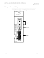
(5) Precautions on wiring
In order to avoid the effects of noise, the DeviceNet communication cable, power
cable and signal lines for the I/O module should be installed in such a way that
they are sufficiently away from each other.
(6) Remote operation is not allowed from other DeviceNet node
Each DeviceNet node on DeviceNet cannot read/write/monitor the sequence
program or data of the PLC CPU where the QJ71DN91 is installed.
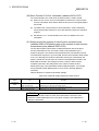
2.3 How to Check the Function Version, Serial No. and Software Version
This section describes how to check the function version and serial No. of the
QJ71DN91 and the GX Configurator-DN software version.
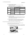
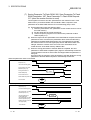
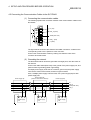
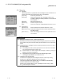
(1) How to check the function version and serial No. of the QJ71DN91
(a) To check the version using the "SERIAL column of the rating plate" located
on the side of the module
Serial No. (first 5 digits)
Function version
03052
(b) To check the version using the GX Developer
See Section 9.3 of this manual.
2-4
2-4
2 SYSTEM CONFIGURATION
MELSEC-Q
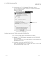
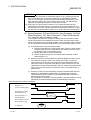
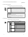
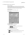
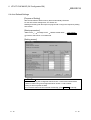
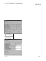
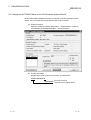
(2) How to check the GX Configuration-DN software version
The GX Configurator-DN software version can be checked in GX Developer's
"Product information" screen.
[Startup procedure]
GX Developer
"Help"
Product information
Software version
(In the case of GX Developer Version 7)
2.4 About Use of the QJ71DN91 with the Q00J/Q00/Q01CPU
Here, use of the QJ71DN91 with the Q00J/Q00/Q01CPU is explained.
(1) Number of QJ71DN91 that can be installed when the Q00J/Q00/
Q01CPU is used.
See item 2.2 concerning the number of QJ71DN91 that can be installed when the
Q00J/Q00/Q01CPU is used.
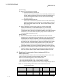
(2) Limitations when using the Q00J/Q00/Q01CPU
When using Q00J/Q00/Q01CPU, use QJ71DN91 which function version is B and
first 5 digits of the serial No. is 03052 or later.
2-5
2-5
2 SYSTEM CONFIGURATION
MELSEC-Q
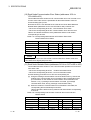
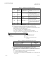
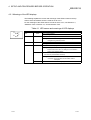
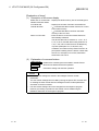
2.5 About Additional Function
The added function is described below.
Function
Serial No.
Function Outline
Addition of Each Node Communication
First five digits of
Indicates whether an I/O
Error Status (addresses 01C0H to 01C3H
serial No. are
communication error has
/448 to 451)
04102 or later
occurred or not in each node.
Reference Section
Section 3.4.1 (10)
POINT
Refer to Section 2.3 for the way to confirm the serial No.
2.6 Compatible DeviceNet Products from Other Manufacturers
It is assumed that most of the DeviceNet products on the market are compatible.
However, compatibility with the products of other manufacturers is not guaranteed.
2-6
2-6
3 SPECIFICATIONS
MELSEC-Q
3 SPECIFICATIONS
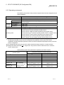
3.1 Performance Specifications
This section explains the performance specifications for QJ71DN91, I/O signals for
PLC CPU and specifications for buffer memory.
See the PLC CPU User's Manual to be used for the general specifications for
QJ71DN91.
Item
Node type
3
Communication specifications
When
master
function
When slave
function
Node numbers which can be set
Number of
connections Message connection
that be
I/O connection
created
I/O
Send
communicaAmount of
Receive
tion
communica- Message
Send
tion data
communicaReceive
tion
Specifications
Device net master (Group 2 only client)
0 to 63
63
63 (polling, bit strobe, change of state, cyclic)
Max. 4096 points (512 bytes), max. 256 bytes per 1 node
Max. 4096 points (512 bytes), max. 256 bytes per 1 node
Max. 240 bytes
Max. 240 bytes
Node type
Device net slaves (Group 2 server)
Setting possible node number
Number of
connections
I/O connection
that can be
created
Amount of
I/O
Send
communica- communicaReceive
tion data
tion
0 to 63
Communications speed
1 (polling)
Max. 1024 points (128 bytes)
Max. 1024 points (128 bytes)
One speed can be selected from 125 kbps, 250 kbps and 500kbps.
Maximum transmitting distance of
Length of drop line
trunk line
Communic
ations
speed
Maximum cable length
Current consumption required on the network
Thick
Cables
125 kbaud
500 m
250 kbaud
250 m
500 kbaud
100 m
Thin
Cables
Thick and
thin cables Maximum
coexist
100 m
See 3.1.1
Total
156 m
78 m
6m
39 m
0.03 A
Number of times to write flash ROM
Max. 100000 times
No. of I/O occupied points
32 points (I/O allocation: Intelligent 32 points)
5 V DC internal current consumption
0.17 A
Weight
0.11 kg
: The maximum cable length complies with that in the device net specification (Release 2.0) Volumes 1 and 2.
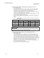
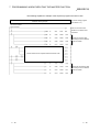
3.1.1 Maximum transmitting distance when thick and thin cables coexist
The table below lists both the maximum transmitting distance when thick and thin
cables coexist.
Communication speed
125 kbaud
250 kbaud
500 kbaud
3-1
Maximum transmitting distance of trunk line when thick
and thin cables coexist
Thick cable length + 5 Thin Cable length < 500 m
Thick cable length +2.5 Thin cable length < 250 m
Thick cable length + Thin cable length < 100 m
3-1
3 SPECIFICATIONS
MELSEC-Q
3.2 Functions
This section explains the functions of the QJ71DN91.
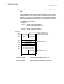
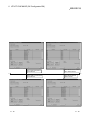
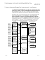
3.2.1 Master function (I/O communication function)
The I/O communication function executes the I/O data communication with each slave
node.
In the I/O communication function, the connection type can be set according to the
specification of the slave node.
There are four connection types: polling, bit strobe, change-of-state, and cyclic. The
connection type can be set with a parameter.
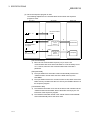
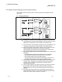
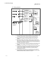
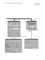
(1) When GX Configurator-DN is used
The following explains the I/O communication function when the GX
Configurator-DN is used.
PLC CPU
QJ71DN91
1)
SET Y11
3)
X
Slave node
I/O communication
request
0700H
2)
Master function
receive
data area
Transmission
07FFH
4)
Y
0900H
5)
Master function
transmit
data area
Reception
09FFH
[I/O communication]
1) When the I/O communication request (Y11) is set, the I/O
communication with each slave node starts. It is not necessary to set
Y11, however, when the auto communication start is set with a
parameter.
[Reception data]
2) The input status from each slave node is automatically stored in the
"master function reception data" area of the buffer memory in the
QJ71DN91.
3) The input status stored in the "master function reception data" area of
the buffer memory is loaded onto the PLC CPU by the auto refresh
setting.
[Transmission data]
4) The ON/OFF information to be sent to the slave node is written into the
"master function transmission data" area of the buffer memory by the
auto refresh setting.
5) The ON/OFF information stored in the "master function transmission
data" area is automatically sent to a slave node.
3-2
3-2
3
3 SPECIFICATIONS
MELSEC-Q
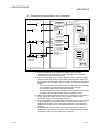
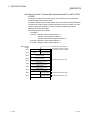
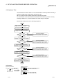
(2) When the sequence program is used
The following explains the I/O communication function when the sequence
program is used.
PLC CPU
QJ71DN91
1)
SET Y11
3)
FROM
I/O communication
request
2)
0700H
Master function
receive
data area
X01
I/O communication
in progress
Transmission
07FFH
4)
TO
Slave node
0900H
3)
Master function
transmit
data area
X01
I/O communicating
Reception
09FFH
[I/O communication]
1) When the I/O communication request (Y11) is set, the I/O
communication with each slave node starts. It is not necessary to set
Y11, however, when the auto communication start is set with a
parameter.
[Reception data]
2) The input status from each slave node is automatically stored in the
"master function receive data" area of the buffer memory in the
QJ71DN91.
3) The input status stored in the "master function receive data" area of the
buffer memory is loaded onto the PLC CPU by the FROM instruction of
the sequence program.
[Transmission data]
4) The ON/OFF information to be sent to the slave node is written into the
"master function transmit data" area of the buffer memory by the TO
instruction of the sequence program.
5) The ON/OFF information stored in the "master function transmit data"
area is automatically sent to the slave node.
3-3
3-3
3 SPECIFICATIONS
MELSEC-Q
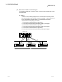
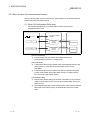
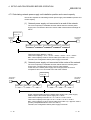
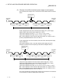
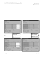
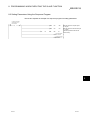
(3) Overview of each connection type
The following explains an overview of each connection type used during the I/O
communication.
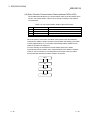
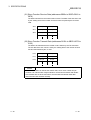
(a) Polling
As shown in the following diagram, the communication method by which
the communication with each slave node is repeated, as described from 1)
to 6), is the polling communication. The connection that uses this
communication is the polling connection.
1) The master node transmits the output data.
2) The slave node transmits input data by setting 1) to trigger.
3) The master node transmits the output data.
4) The slave node transmits input data by setting 3) to trigger.
5) The master node transmits the output data.
6) The slave node transmits input data by setting 5) to trigger.
Master node
1)
4)
6)
5)
3)
2)
Slave node
3-4
3-4
3 SPECIFICATIONS
MELSEC-Q
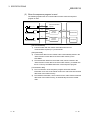
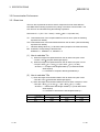
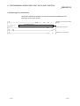
(b) Bit strobe
As shown in the following diagram, the communication method by which
the communication with each slave node is repeated, as described from 1)
to 4), is the bit strobe communication. The connection that uses this
communication is the bit strobe connection.
1) Output information of a maximum of one bit is transmitted
simultaneously to each slave node.
2) The slave node transmits the input data by setting the transmission of
1) to trigger.
3) The slave node transmits the input data by setting the transmission of
1) to trigger.
4) The slave node transmits the input data by setting the transmission of
1) to trigger.
Master node
4)
2)
1)
3)
Slave node
3-5
3-5
3 SPECIFICATIONS
MELSEC-Q
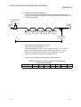
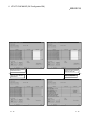
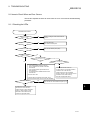
(c) Change-of-state
As shown in the following diagram, the communication method that
executes the communication of [1] and [2] as the I/O data changes is the
change-of-state communication, and the connection that uses this
communication is the change-of-state connection.
No data transmission is performed unless the I/O data is changed.
1) When the output data of the master node changes, the data is sent to
the slave node.
2) When the input data of the slave node changes, the data is sent to the
master node.
There is no concept of the network scan in the change-of-state
communication.
Master node
1)
2)
Slave node
3-6
3-6
3 SPECIFICATIONS
MELSEC-Q
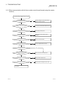
(d) Cyclic
As shown in the following diagram, the communication method that
regularly repeats the communication of [1] and [2] is the cyclic
communication, and the connection that uses this communication is the
cyclic connection.
1) The data of the master node is sent to the slave node.
2) The data of the slave node is sent to the master node.
The cycle of the cyclic communication can be specified for each slave
node.
Specify the cycle of the cyclic communication in the following parameter
items:
Transmission cycle from master node: Production inhibit time
Transmission cycle from slave node: Expected packet rate
There is no concept of the network scan in the cyclic communication.
Master node
1)
2)
Slave node
3-7
3-7
3 SPECIFICATIONS
MELSEC-Q
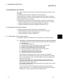
3.2.2 Master function (Message communication function)
The message communication function is used to get and set the attribute data of a
slave node.
(1) Getting attributes
PLC CPU
QJ71DN91
0110H
1)
TO
Message
communication
command area
Slave node (MAC ID)
2)
Instance
011FH
Message
communication
request
2)
SET Y12
Class
Attribute
Attribute
Instance
Attribute
0120H
6)
FROM
X02 X05
012FH
0130H
01A7H
4)
FROM
X02 X05
Message communication
completion
5)
Message
communication
result area
Message
communication
data area
Message
communication
complete
3)
Class
Instance
Attribute
Instance
Attribute
Attribute
Attribute
: In DeviceNet, the area used for reading and writing via communication
is specified by the numbers representing the class ID, instance ID, and
attribute ID. For details, refer to the manual of each slave node.
1) The TO instruction of the sequence program sets to get attributes in the
"message communication command" area of the buffer memory.
2) When the message communication request (Y12) is turned ON by the
sequence program, the data, which is set in the "message
communication command" area in the buffer memory, is sent to the
slave node and the message communication starts.
3) When the QJ71DN91 receives data from the slave node, it is processed
as follows:
• The specific data of the slave node that is set in the "message
communication command" area is stored in the "message
communication data" area of the buffer memory.
• The processing result of message communication is stored in the
"message communication result" area of the buffer memory.
4) The message communication is completed when the processing result
is stored in the "message communication result" area of the buffer
memory, and the message communication completion (X02) is
automatically turned ON.
5) Upon normal completion, the data in the slave node, which is stored in
the "message communication data" area of the buffer memory, is
loaded onto the PLC CPU by the FROM instruction of the sequence
program.
6) If the message communication error signal (X05) is turned ON, the
FROM instruction reads the contents of the "message communication
result" area, and the cause of the error is verified.
3-8
3-8
3 SPECIFICATIONS
MELSEC-Q
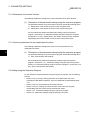
(2) Setting attributes
PLC CPU
QJ71DN91
1)
0110H
TO
011FH
2)
0130H
TO
3)
SET Y12
012FH
Next
processing
X02 X05
Message
communication
completion
3)
Class
Instance
Attribute
Message
communication
data area
Attribute
01A7H
Message
communication
request
0120H
5)
Message
communication
command area
Slave node (MAC ID)
Message
communication
result area
Class
4)
Instance
Attribute
Message
communication
complete
Instance
Attribute
6)
Attribute
Class
Instance
Attribute
Attribute
Instance
Attribute
1) The TO instruction of the sequence program sets to set attributes in the
"message communication command" area of the buffer memory.
2) The TO instruction of the sequence program writes the data to be
written in the "message communication data" area of the buffer
memory.
3) When the message communication request (Y12) is turned ON, the
data, which is stored in the "message communication data" area of the
buffer memory, is written to the slave node in the area specified by the
"message communication command."
4) When the write process is finished, the message communication result
is stored in the "message communication result" area of the buffer
memory.
5) The message communication is completed when the processing result
is stored in the "message communication result" area of the buffer
memory, and the message communication completion (X02) is
automatically turned ON.
6) If the message communication error signal (X05) is turned ON, the
FROM instruction reads the contents of the "message communication
result" area, and the cause of the error is verified.
3-9
3-9
3 SPECIFICATIONS
MELSEC-Q
(3) Reading the communication error information
PLC CPU
QJ71DN91
0110H
1)
TO
Message
communication
command area
2)
Slave
information
storage area
0120H
5)
FROM
X02 X05
012FH
0130H
01A7H
3)
X02 X05
Message communication
completion
I/O
communication
Class 1
Instance
011FH
Message
communication
request
SET Y12
FROM
Slave node (MAC ID)
Attribute
Attribute
Instance
2)
Attribute
Attribute
Message
communication
result area
Message
communication
data area
Message
communication
complete
4)
Attribute
Class
Instance
Attribute
Attribute
Attribute
Instance
Attribute
The status of each slave station is stored during I/O communication.
1) The TO instruction of the sequence program sets to read the
communication error information in the "message communication
command" area of the buffer memory.
2) When the message communication request (Y12) is turned ON by the
sequence program, the error information of the applicable slave node
that has been accumulated in the QJ71DN91 is read and processed as
follows:
• The error information of the slave node that was set by the "message
communication command" area is stored in the "message
communication data" area of the buffer memory.
• The processing result of the message communication is stored in the
"message communication result" area of the buffer memory.
3) When the processing result is stored in the "message communication
result" area of the buffer memory, the message communication
completion (X02) is automatically turned ON.
4) The communication error information of the slave node, which is stored
in the "message communication data" area of the buffer memory, is
loaded onto the PLC CPU by the FROM instruction of the sequence
program.
5) If the message communication error signal (X05) is turned ON, the
FROM instruction reads the contents of the "message communication
result" area, and the cause of the error is verified.
3 - 10
3 - 10
3 SPECIFICATIONS
MELSEC-Q
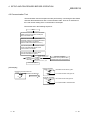
3.2.3 Slave function (I/O communication function)
The I/O communication function executes the communication of the I/O data with the
master node using the polling method.
(1) When GX Configurator-DN is used
The following explains the I/O communication function when the GX
Configurator-DN is used.
PLC CPU
QJ71DN91
1)
I/O communication
request
SET Y11
3)
0B00H
X
0B3FH
4)
Master node
0C00H
Y
0C3FH
Slave function
receive
data area
Slave function
transmit
data area
2)
Transmission
5)
Reception
[I/O communication]
1) Communication with the master node starts when the I/O
communication request (Y11) is turned ON.
[Reception data]
2) Transmission data from the master node is automatically stored in the
"slave function receive data" area of the buffer memory in the
QJ71DN91.
3) Transmission data from the mater node, which is stored in the "slave
function receive data" area of the buffer memory, is loaded onto the
PLC CPU by the auto refresh setting.
[Transmission data]
4) With the auto refresh setting, the ON/OFF information to be sent to the
master node is written in the "slave function transmit data" area of the
buffer memory.
5) The ON/OFF information, which is stored in the "slave function transmit
data" area of the buffer memory, is automatically sent to the master
node.
3 - 11
3 - 11
3 SPECIFICATIONS
MELSEC-Q
(2) When the sequence program is used
The following explains the I/O communication function when the sequence
program is used.
PLC CPU
QJ71DN91
1)
SET Y11
3)
I/O communication
request
0B00H
FROM
X01
I/O communicating
0B3FH
4)
0C00H
TO
X01
I/O communicating
Master node
0C3FH
Slave function
receive
data area
Slave function
transmit
data area
2)
Transmission
5)
Reception
[I/O communication]
1) Communication with the master node starts when the I/O
communication request (Y11) is turned ON.
[Reception data]
2) Transmission data from the master node is automatically stored in the
"slave function receive data" area of the buffer memory in the
QJ71DN91.
3) The transmission data from the master node, which is stored in the
"slave function receive data" area of the buffer memory, is loaded onto
the PLC CPU by the FROM instruction of the sequence program.
[Transmission data]
4) The TO instruction of the sequence program writes the ON/OFF
information to be sent to the master node in the "slave function transmit
data" area of the buffer memory.
5) The ON/OFF information, which is stored in the "slave function transmit
data" area of the buffer memory, is automatically sent to the master
node.
3 - 12
3 - 12
3 SPECIFICATIONS
MELSEC-Q
3.3 I/O Signals for the PLC CPU
This section explains the input/output signals for the PLC CPU of the QJ71DN91.
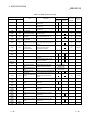
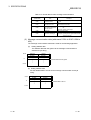
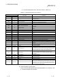
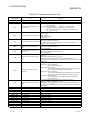
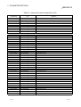
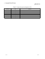
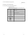
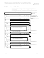
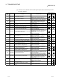
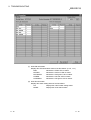
3.3.1 I/O signal list
The I/O signal list for the QJ71DN91 is shown in Table 3.2.
The I/O numbers (X/Y) and I/O addresses described from this chapter are applicable
when the QJ71DN91 is installed in slot 0 of the basic base module.
Table 3.2 I/O signal list
QJ71DN91
Input number
X00
X01
PLC CPU
Signal name
X08
X09
Watchdog Timer Error
I/O Communicating
Message Communication
Completion
Master Function For Error Set Signal
Slave Down Signal
Message Communication Error
Signal
Saving Parameter To The Flash
ROM
Save Parameter To Flash ROM
Completion
Slave Function For Error Set Signal
Use prohibited
X0A
H/W Testing
X0B
H/W Test Completion
X0C
H/W Test Error Detection
X02
X03
X04
X05
X06
X07
X0D
X0E
X0F
X10
X11
X12
PLC CPU
Usability
Master
Slave
function
function
Signal name
Usability
Master
Slave
function function
Y00
Y01
—
Y02
—
—
Y03
Y04
—
Y05
Y06
Y07
—
—
—
At the time of the
hardware test
At the time of the
hardware test
At the time of the
hardware test
Use prohibited
—
—
—
—
Module Ready
Use prohibited
X13
X14
X15
X16
Output number
QJ71DN91
Y08
Y09
—
—
Y0C
Y0D
Y0E
Y0F
Y10
Y11
Y12
Y14
Y15
Y16
Y17
X18
Y18
X19
X1A
X1B
X1C
X1D
X1E
X1F
Y19
Y1A
Y1B
Y1C
Y1D
Y1E
Y1F
—
—
—
Y0B
X17
Use prohibited
—
Y0A
Y13
Auto Configuration Executing
Auto Configuration Completion
Use prohibited
I/O Communication Request
Message Communication Request
Master Function For Error Reset
Request
Use prohibited
Auto Configuration Request
Use prohibited
Save Parameter To Flash ROM
Request
Slave Function For Error Reset
Request
Use prohibited
—
—
—
—
—
—
—
—
—
—
IMPORTANT
The use-prohibited output signals shown in Table 3.2 are accessed by the system
and cannot be accessed by the user. In the event these signals are used (turned
ON/OFF) by the user, normal operations cannot be guaranteed.
3 - 13
3 - 13
3 SPECIFICATIONS
MELSEC-Q
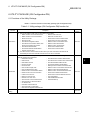
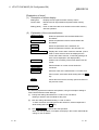
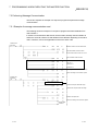
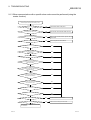
3.3.2 Details of the I/O signals
The following describes the ON/OFF timings and conditions of the I/O signals.
(1) Watchdog Timer Error: X00
This is turned ON when an error occurs in the QJ71DN91.
OFF: Module normal
ON: Module error
Watchdog timer error (X00)
Module ready (X0F)
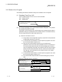
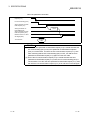
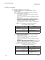
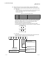
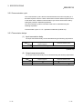
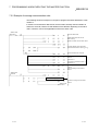
(2) I/O Communicating: X01, I/O Communication Request: Y11 (when
the master function is used)
This signal is used to start the I/O communication of the master function with the
parameters set by the "parameters for the master function" of the buffer memory.
Use this signal while the module ready (X0F) is ON.
(a) When the auto start is not set:
1) Verify that the auto configuration request (Y15) and the save parameter
to flash ROM request (Y17) are OFF.
2) To start the I/O communication, use the sequence program to turn ON
the I/O communication request (Y11).
3) When the I/O communication request (Y11) is turned ON, the
parameter check is executed. If the parameter check is successful, the
I/O communication starts and the I/O Communicating (X01) is turned
ON. If the parameter check fails, the master function for error set signal
(X03) is turned ON and the ERR. LED is lit. Check the contents of the
error with the "error information for the master function" of the buffer
memory address 1B1H.
4) To stop the I/O communication, use the sequence program to turn OFF
the I/O communication request (Y11).
5) I/O communication stops and the I/O communicating (X01) is turned
OFF.
When the parameter check is successful
Module Ready (X0F)
I/O Communication Request (Y11)
Parameter
check
I/O Communicating (X01)
When the parameter check fails
Module Ready (X0F)
I/O Communication Request (Y11)
Parameter
check
I/O Communicating
Master Function For Error Set Signal
3 - 14
3 - 14
3 SPECIFICATIONS
MELSEC-Q
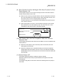
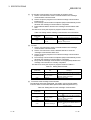
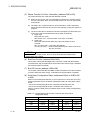
(b) When the auto start is set
1) The module ready (X0F) is turned ON when the power is turned ON,
and the parameter check is executed automatically.
2) If the parameter check is successful, the I/O communication starts and
the I/O communicating (X01) is turned ON. If the parameter check fails,
the master function for error set signal (X03) is turned ON and the ERR.
LED is lit. Check the contents of the error with the "master function for
error information" of the buffer memory address 1B1H.
POINT
To stop the I/O communication, set Y11, then reset after 200 ms or longer.
When the parameter check is successful:
Module Ready (X0F)
Parameter
check
I/O Communicating (X01)
When the parameter check fails:
Module Ready (X0F)
Parameter
check
I/O Communicating (X01)
Master Function For Error
Set Signal (X03)
3 - 15
3 - 15
3 SPECIFICATIONS
MELSEC-Q
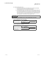
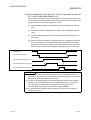
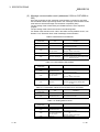
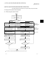
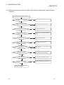
(3) I/O Communicating : X01, I/O Communication Request: Y11 (when
the slave function is used)
These signals are used to start the I/O communication of the slave function with
the number of I/O points that is set by the "setting area of the number of slave
function reception bytes" and the "setting area of the number of slave function
transmission bytes" of the buffer memory.
Use these signals while the module ready (X0F) is ON.
(a) To start the I/O communication, use the sequence program to turn ON the
I/O communication request (Y11).
(b) When the I/O communication request (Y11) is turned ON, the parameter
check is executed. If the parameter check is successful, the I/O
communication starts and the I/O communicating (X01) is turned ON. If the
parameter check fails, the slave function for error set signal (X08) is turned
ON and the ERR. LED is lit. Check the contents of the error with the "error
information for the slave function" of the buffer memory address 601H.
(c) To stop the I/O communication, use the sequence program to turn OFF the
I/O communication request (Y11).
(d) The I/O communication stops and the I/O communicating (X01) is turned
OFF.
When the parameter check is successful:
Module Ready (X0F)
I/O Communication
Request (Y11)
I/O Communicating (X01)
Parameter
check
When the parameter check fails:
Module Ready (X0F)
I/O Communication Request
(Y11)
Parameter
check
I/O communicating (X01)
Slave Function For Error Set
Signal (X08)
3 - 16
3 - 16
3 SPECIFICATIONS
MELSEC-Q
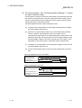
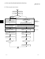
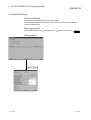
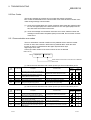
(4) Message Communication Completion: X02, Message
Communication Error Signal: X05, Message Communication
Request: Y12
These signals are used to execute the message communication. Message
communication can be executed when the "master function communication
status" area of the buffer memory is "in operation (C0H)" or "stop (40H)".
POINT
When making message communication, set the master function parameters.
If the master function parameters have not been set, a message connection is
opened using message group 1.
(a) The procedure for executing the message communication is as follows:
1) Write the message communication data into the "message
communication command" area of the buffer memory.
2) Use the sequence program to turn ON the message communication
request (Y12).
(Set an interval of 100 ms or longer before turning ON the message
communication request.)
(b) The message communication is completed. The communication result is
written into the "message communication result" area, and the message
communication completion (X02) is turned ON.
(c) Check the message communication result with the message communication
error signal (X05).
(d) After reading the communication data by the FROM instruction, use the
sequence program to turn OFF the message communication request (Y12).
The message communication completion (X02) and the message
communication error signal (X05) are automatically turned OFF.
Message Communication
Request (Y12)
Message Communication
Completion (X02)
With an error
No error
Message Communication
Error Signal (X05)
FROM/TO
Write command
for the message
communication
(TO instruction)
Write data for
the message
communication
(TO instruction)
(During data transmission only)
3 - 17
Read result for
the message
communication
(FROM instruction)
Read data for
the message
communication
(FROM instruction)
(During data reception only)
3 - 17
3 SPECIFICATIONS
MELSEC-Q
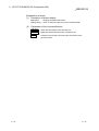
(5) Master Function For Error Set Signal: X03, Master Function For
Error Reset Request: Y13
These signals are used to indicate an error while executing the master function
and to reset the error code.
(a)
When an error occurs via the master function, the error information is stored
in the "error information for the master function" area of the buffer memory
and the master function for error set signal (X03) is turned ON.
The master function for error set signal is automatically turned OFF when
the error cause is removed.
(b) After removing the error cause, use the sequence program to turn ON the
master function for error reset request (Y13), and the error code of the
"error-information for the master function" area is cleared.
Master Function For Error
Reset Request (Y13)
Error code
clear
Master Function For Error
Set Signal (X03)
FROM/TO
Read error
information
(FROM instruction)
(6) Slave Down Signal: X04
This signal indicates whether or not a slave node that is being stopped for
communication exists.
3 - 18
(a)
This signal is turned ON when at least one slave node is being stopped
among the slave nodes that are set by the parameters.
OFF: Normal communication with all nodes
ON: A communication-error node exists.
The slave node that is being sopped can be checked by referring to the
"each node's communication status" area in the addresses 01BCH to
01BFH of the buffer memory.
(b)
X04 is automatically turned OFF when communication with the slave node
that is being stopped resumes.
3 - 18
3 SPECIFICATIONS
MELSEC-Q
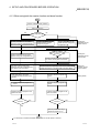
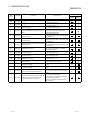
(7) Saving Parameter To Flash ROM: X06, Save Parameter To Flash
ROM Completion: X07, Save Parameter To Flash ROM Request:
Y17 (when the master function is used)
These signals are used to save the "parameters for the master function" of the
buffer memory to the flash ROM in the QJ71DN91. Make a request to save
parameters to the flash ROM while the I/O communicating (X01) is OFF.
(a) Set the parameters using the following steps:
1) Write the parameters in the "parameters for the master function" area of
the buffer memory.
2) Set the parameter save area selection bit.
3) Use the sequence program to turn ON the save parameter to flash
ROM request (Y17).
(b) When the request to save parameters to the flash ROM is accepted, and if the
parameter check is successful, the parameters will be saved and the saving
parameter to the flash ROM (X06) will turn ON. If the parameter check fails,
the master function for error set signal (X03) will turn ON and the ERR. LED
will light. Check the contents of the error in the "error information for the
master function" of the buffer memory address 1B1H.
(c) When the saving parameters to the flash ROM is completed, the save
parameter to flash ROM completion (X07) signal is automatically turned ON.
Communications with other slave nodes are stopped while the parameter is
being set.
By turning OFF the request to save parameters to the flash ROM, the saving
parameter to the flash ROM complete is automatically turned OFF.
When the parameter check is successful
I/O Communication
Request (Y11)
I/O Communicating (X01)
Save Paramter To Flash
ROM Request (Y17)
Parameter
check
Saving Parameter To
Flash ROM (X06)
Save Parameters To
Flash ROM Completion (X07)
TO instruction
Write
parameter
data
When the parameter check fails
I/O Communication
Request (Y11)
I/O Communicating (X01)
Save Parameter To Flash
ROM Request (Y17)
Parameter
check
Saving Parameter To
Flash ROM (X06)
Save Parameter To Flash
ROM Completion (X07)
Master Function For Error
Set Signal (X03)
TO instruction
3 - 19
Write
parameter
data
3 - 19
3 SPECIFICATIONS
MELSEC-Q
POINT
(1) Even if the save parameter to flash ROM request (Y17) is turned ON while the
I/O communicating (X01) is ON, save parameter to flash ROM completion
(X07) is not turned ON. Turn OFF the I/O communication request (Y11), then
after confirming that the I/O communicating (X01) is OFF, turn ON the save
parameter to flash ROM request (Y17) from the OFF state.
(2) Even if the I/O communication request (Y11) is turned ON while the save
parameter to flash ROM request (Y17) is ON, the I/O communicating (X01) is
not turned ON. Turn OFF the save parameter to flash ROM request (Y17), then
turn OFF the I/O communication request (Y11) once and turn it back ON again.
(8) Saving Parameter To Flash ROM: X06, Save Parameter To Flash
ROM Completion: X07, Save Parameter To Flash ROM Request:
Y17 (when the slave function is used)
These signals are used when saving the "setting area for the number of slave
function input points" and "setting area for the number of slave function output
points" of the buffer memory to the flash ROM in the QJ71DN91. Make a request
to save parameters to the flash ROM while the I/O communicating (X01) is OFF.
(a) Set the parameters using the following steps:
1) Write the parameter in the "setting area of the number of slave function
reception bytes" and the "setting area of the number of slave function
transmission bytes" of the buffer memory.
2) Set the parameter save area selection bit.
3) Use the sequence program to turn ON the save parameter to flash
ROM request (Y17).
(b) When the request to save parameters to the flash ROM is accepted, and if
the number of I/O points check is successful, the number of I/O points
setting will be saved and the save parameter to flash ROM (X06) will turn
ON. If the number of I/O points check fails, the slave function for error set
signal (X08) is turned ON and the ERR. LED is lit. Check the contents of the
error in the "error information for the slave function" of the buffer memory
address 601H.
(c) When the number of I/O points setting is saved in the flash ROM, the save
parameter to flash ROM completion (X07) is automatically turned ON.
Communication with the master node is stopped while the number of I/O
points setting is being saved.
By turning OFF the request to save parameters to the flash ROM, the saving
parameters to the flash ROM complete is automatically turned OFF.
When the parameter check is successful
I/O Communication
Request (Y11)
I/O Communicating (X01)
Save Paramter To Flash
ROM Request (Y17)
Parameter
check
Saving Parameter To
Flash ROM (X06)
Save Parameter To Flash
ROM Completion (X07)
TO instruction
3 - 20
Write
parameter
data
3 - 20
3 SPECIFICATIONS
MELSEC-Q
When the parameter check fails:
I/O Communication
Request (Y11)
I/O Communicating (X01)
Save Parameter To Flash
ROM request (Y17)
Parameter
check
Saving Parameter To
Flash ROM (X06)
Save Parameter To Flash
ROM Completion (X07)
Master Function For Error
Set Signal (X03)
Write
parameter
data
TO instruction
POINT
(1) Even if the save parameter to flash ROM request (Y17) is turned ON while the
I/O communicating (X01) is ON, save parameter to flash ROM completion
(X07) is not turned ON. Turn OFF the I/O communication request (Y11), then
after confirming that the I/O communicating (X01) is OFF, turn ON the save
parameter to flash ROM request (Y17) again from the OFF state.
(2) Even if the I/O communication request (Y11) is turned ON while the save
parameter to flash ROM request (Y17) is ON, the I/O communicating (X01) is
not turned ON. Turn OFF the save parameter to flash ROM request (Y17), then
turn OFF the I/O communication request (Y11) once and turn it back ON again.
3 - 21
3 - 21
3 SPECIFICATIONS
MELSEC-Q
(9) Slave Function For Error Set Signal: X08, Slave Function For Error
Reset Request: Y18
These signals notify an error occurrence during execution of the slave function
and are used to reset the error code.
(a) When an error occurs by the slave function, the error information is stored in
the "error information for the slave function" area of the buffer memory, and
the slave function for error set signal (X08) is turned ON.
The slave function for error set signal is automatically turned OFF when the
error cause is removed.
(b) After removing the error cause, use the sequence program to turn ON the
slave function for error reset request (Y18). The error code of the "error
information for the slave function" area will be cleared.
Slave Function For Error Reset
Request (Y18)
Error code
clear
Slave Function For Error Set
Signal (X08)
FROM instruction
Read error
information
(FROM instruction)
(10) H/W Testing: X0A, H/W Test Completion: X0B, H/W Test Error
Detection: X0C
These signals indicate the status when the QJ71DN91 is set to the hardware test
mode (mode 9).
(a) When the mode switch is set to 9 and the power is turned ON, the H/W
testing (X0A) is turned ON.
(b) When the hardware test is completed normally, the H/W test completion
(X0B) signal will be turned ON. If an error occurs, the H/W test completion
(X0B) signal will not be turned ON but the H/W test error detection (X0C) will
be turned ON.
(11) Module Ready: X0F
This signal indicates whether the module is ready to operate.
When the module reaches ready-to-operate status, this signal is turned ON
automatically.
The module ready (X0F) is turned OFF when the watchdog timer error (X00) is
turned ON.
3 - 22
3 - 22
3 SPECIFICATIONS
MELSEC-Q
(12) Auto Configuration Executing: X14, Auto Configuration Completion:
X15, Auto Configuration Request: Y15
These signals are used in order to search the slave nodes that are connected to
the network and create parameters automatically. Execute the auto configuration
request while the I/O communicating (X01) is OFF.
(a) Verify that the DeviceNet device power and the network power are turned
ON.
(b) To execute the auto configuration, turn ON the auto configuration request
(Y15).
(c) The auto configuration starts and the auto configuration executing (X14) is
turned ON.
(d) When the auto configuration is completed, the auto configuration executing
(X14) is turned OFF and the parameters generated by auto configuration
processing is stored in the "parameters for the master function" area of the
buffer memory, and the auto configuration completion (X15) is turned ON.
I/O Communication
Request (Y11)
I/O Communicating (X01)
Auto Configuration Request (Y15)
Auto Configuration Executing (X14)
Auto Configuration Completion (X15)
POINT
(1) Confirm that the I/O communication request (Y11) is turned OFF. When Y11 is
turned OFF, not only the I/O communication of the master function, but also the
I/O communication of the slave function stops.
(2) The I/O communicating (X01) is not turned ON even if the I/O communication
request (Y11) is turned ON while the auto configuration request (Y15) is ON.
Turn OFF the auto configuration request (Y15), then turn OFF the I/O
communication request (Y11) once, then turn it back ON again.
(3) For the parameters created by auto configuration, be sure to verify that the
contents are correct.
3 - 23
3 - 23
3 SPECIFICATIONS
MELSEC-Q
3.4 Buffer Memory
The buffer memory transfers data between the QJ71DN91 and the PLC CPU.
The FROM and TO instructions of the PLC CPU are used to read and write the buffer
memory data in the QJ71DN91.
The contents of the buffer memory are reset to 0 when the power is turned OFF or
when the PLC CPU is reset.
However, the "parameter" area is initialized using the saved parameters if the
parameters have been saved in the flash ROM.
3.4.1 Buffer memory list
The buffer memory list is shown in Table 3.3.
Table 3.3 Buffer memory list (1/2)
Address
Hexadecimal
0000H to
010FH
0110H to
011FH
0120H to
012FH
0130H to
01A7H
01A8H to
01AFH
Decimal
256 to 271
272 to 287
288 to 303
304 to 423
424 to 431
Item
Use prohibited
Message communication
command
Message communication
result
Message communication
data
Use prohibited
01B0H
432
Master Function
Communication Status
01B1H
433
Master Function For Error
Information
01B2H
434
Bus Error Counter
01B3H
435
01B4H to
01B7H
01B8H to
01BBH
01BCH to
01BFH
01C0H to
01C3H
01C4H to
01C7H
01C8H to
01CBH
Bus Off Counter
436 to 439
Each Node Configuration
Status
440 to 443
Use prohibited
444 to 447
448 to 451
452 to 455
Each Node
Communication Status
Each Node
Communication Error
Status
Each Node Obstacle
Status
456 to 459
Use prohibited
01CCH to
01CFH
460 to 463
Down Node Detection
Disable Status
01D0H to
01D3H
464 to 467
Use prohibited
01D4H to
03CFH
468 to 975
Parameters for the master
function
03D0H to
03EFH
976 to 1007
Use prohibited
03F0H
1008
03F1H to
04FFH
0500H to
05FBH
3 - 24
Auto configuration
operation setting
1009 to 1279
Use prohibited
1280 to 1531
Master Function For I/O
Address Area
Description
—
Usability
Master
Slave
function
function
—
Stores the request data for executing
the message communication.
Stores the result data of the message
communication.
Stores the transmission and reception
data of the message communication.
—
—
Stores the communication status of
the master function.
Higher byte: Error code
Lower byte: Stores the node number
where the error occurred.
Stores the number of times errors are
detected in the communication data.
Stores the number of communication
errors.
Indicates whether or not each slave
node is set with a parameter.
—
—
Indicates whether or not each node is
executing I/O communication.
Indicates whether an I/O
communication error has occurred or
not in each node.
Indicates whether or not each node
has a trouble.
—
—
Sets whether or not the "slave down"
signal (X04) reflects the down status
of each slave node.
—
—
Area for setting parameters for the
master function by the sequence
program.
—
—
Sets up the operation of the auto
configuration.
—
Displays the address and size of each
I/O data for the master function.
—
Write from the
PLC CPU
allowed?
Reference
section
—
—
—
—
Yes
3.4.2 (1)
—
No
3.4.2 (2)
—
Yes
3.4.2 (3)
—
—
—
—
No
3.4.2 (4)
—
No
3.4.2 (5)
—
No
3.4.2 (6)
—
No
3.4.2 (7)
—
No
3.4.2 (8)
—
—
—
—
No
3.4.2 (9)
—
No
3.4.2 (10)
—
No
3.4.2 (11)
—
—
—
—
No
3.4.2 (12)
—
—
—
—
Yes
3.4.2 (13)
—
—
—
—
Yes
3.4.2 (14)
—
—
—
—
No
3.4.2 (15)
3 - 24
3 SPECIFICATIONS
MELSEC-Q
Table 3.3 Buffer memory list (2/2)
Address
Usability
Item
Description
Master
function
Slave
function
Write from the
PLC CPU
allowed?
Reference
section
Hexadecimal
Decimal
05FCH
1532
Present Link Scan Time
Displays the current link scan time
(module: ms).
—
No
3.4.2 (16)
05FDH
1533
Minimum Link Scan Time
Displays the minimum link scan time
(module: ms).
—
No
3.4.2 (17)
05FEH
1534
Maximum Link Scan Time
Displays the maximum link scan time
(module: ms).
—
No
3.4.2 (18)
05FFH
1535
Use prohibited
—
—
0600H
1536
Slave Function
Communication Status
Stores the communication status for
the slave function.
—
No
3.4.2 (19)
0601H
1537
Slave Function For Error
Information
Stores the parameter errors, etc.
—
No
3.4.2 (20)
0602H to
060DH
1538 to 1549
—
—
060EH
1550
Setting area of the number Sets the number of reception bytes
of slave function reception for the slave function (reception from
bytes
master).
—
Yes
3.4.2 (21)
060FH
1551
Setting area of the number Sets the number of transmission
of slave function
bytes for the slave function
transmission bytes
(transmission to master).
—
Yes
3.4.2 (21)
0610H to
061FH
1552 to 1567
Use prohibited
—
—
—
0620H to
0624H
1568 to 1572
Model Name Display
“QJ71DN91” is set in ASCII code.
No
3.4.2 (22)
0625H
1573
Node number
Displays the node number currently in
operation.
No
3.4.2 (23)
0626H
1574
Mode Switch Number
Displays the mode switch number
currently in operation.
No
3.4.2 (24)
0627H to
062DH
1575 to 1581
—
—
—
062EH
1582
H/W Test Item Display
Area
Displays the item number of the
hardware test being executed.
At the time of the
hardware test
No
3.4.2 (25)
062FH
1583
H/W Test Result Storing
Area
Stores the result of the hardware test.
At the time of the
hardware test
No
3.4.2 (26)
0630H
1584
Parameter save area
selection bit
Selects area to save to the flash ROM
by the parameter-save request (Y17).
Yes
3.4.2 (27)
0631H
1585
Auto communication start
setting
Selects whether or not to start the I/O
communication automatically at
startup.
Yes
3.4.2 (28)
0632H to
06FFH
1586 to 1791
Use prohibited
—
—
—
0700H to
07FFH
1792 to 2047
Master Function Receive
Data
—
No
3.4.2 (29)
0800H to
08FFH
2048 to 2303
Use prohibited
—
—
—
0900H to
09FFH
2304 to 2559
Master Function Transmit
Data
—
Yes
3.4.2 (30)
0A00H to
0AFFH
2560 to 2815
Use prohibited
—
—
—
0B00H to
0B3FH
2816 to 2879
Slave Function Receive
Data
No
3.4.2 (31)
0B40 to
0BFFH
2880 to 3071
Use prohibited
—
—
0C00H to
0C3FH
3072 to 3135
Slave Function Transmit
Data
Yes
3.4.2 (32)
0C40H to
7FFFH
3136 to
32767
—
—
H
3 - 25
Use prohibited
Use prohibited
Use prohibited
—
—
—
—
—
—
—
—
—
Stores the data received from each
slave node.
—
—
Stores the data to be sent to each
slave node.
—
Stores the data received from the
master node.
—
Stores the data to be sent to the
master node.
—
—
—
—
—
—
—
—
—
—
—
3 - 25
3 SPECIFICATIONS
MELSEC-Q
3.4.2 Buffer memory details
This section explains the details of the buffer memory.
(1) Message communication command (addresses 0110H to
011FH/272 to 287)
Use the TO instruction to write the message communication command.
(a)
To get the attribute data of a slave node
1) Use the TO instruction to set the command data in the "message
communication command" area.
2) Use the sequence program to turn ON the message communication
request (Y12).
3) When the message communication is completed, the message
communication completion (X02) is automatically turned ON.
4) Verify with the message communication error signal (X05) whether or
not the message communication is normally completed.
5) Gotten attribute data is stored in the "message communication data"
area.
The data to be set by the sequence program is listed in Table 3.4.
Table 3.4 Setting data for Get Attribute
Buffer memory address
(hexadecimal)
Description
0110H
Command number
0101H=Get Attribute
0111H
Slave node number (slave
MAC ID), class ID
Lower byte: Node number of the slave node (MAC
ID)
Higher byte: Class ID of the object
0112H
Instance ID
Instance ID of the object
Attribute ID
Lower byte: Attribute ID of the object
Higher byte: Always sets to 0.
0113H
(b)
Item
To set attribute data into the slave node
1) Use the TO instruction to set the command data in the "message
communication command" area.
2) Use the TO instruction to set the attribute data to be set in the
"message communication data" area.
3) Use the sequence program to turn ON the message communication
request (Y12).
4) The message communication completion (X02) is automatically turned
ON when message communication is completed.
5) Verify with the message communication error signal (X05) whether or
nor the message communication is normally completed.
The data to be set by the sequence program is listed in Table 3.5.
Table 3.5 Setting data for Set Attribute
Buffer memory address
(hexadecimal)
Description
0110H
Command number
0102H=Set Attribute
0111H
Slave node number (slave
MAC ID), class ID
Lower byte: Node number of the slave node (MAC
ID)
Higher byte: Class ID of the object
0112H
Instance ID
Instance ID of the object
Attribute ID
Lower byte: Attribute ID of the object
Higher byte: Byte length of the attribute data to be
set
1 to 240 (1H to F0H)
0113H
3 - 26
Item
3 - 26
3 SPECIFICATIONS
MELSEC-Q
(c)
To read the communication error information of the slave node
1) Use the TO instruction to set the command data in the "message
communication command" area.
2) Use the sequence program to turn ON the message communication
request (Y12).
3) The message communication completion (X02) is automatically turned
ON when the message communication is completed.
4) Gotten attribute data is stored in the "message communication data"
area.
The data to be set by the sequence program is listed in Table 3.6.
Table 3.6 Setting data for reading communication error information
Buffer memory address
(hexadecimal)
Item
0110H
Command number
0111H
Slave node number (slave
MAC ID)
Description
0001H=Reads Communication Error Information
Lower byte: Node number of the slave node (MAC
ID)
Higher byte: Always sets to 0.
(d) To reset
1) Use the TO instruction to set the command data in the "message
communication command" area.
2) Use the TO instruction to set the attribute data to be set in the
"message communication data" area.
3) Use the sequence program to turn ON the message communication
request (Y12).
4) The message communication completion (X02) is automatically turned
ON when the message communication is completed.
5) Verify with the message communication error signal (X05) whether the
message communication is normally completed.
The data to be set by the sequence program is listed in Table 3.7.
Table 3.7 Setting data for Reset
Buffer memory address
(hexadecimal)
0110H
0111H
0112H
Item
Description
Command number
0201H=Reset
Lower byte: Node number of the slave node (MAC
Slave node number (slave
ID)
MAC ID), class ID
Higher byte: Class ID of the object
Instance ID
Instance ID of the object
(e) To execute other message communication
The following shows the setting data. For details, refer to the DeviceNet
Common Service of the DeviceNet Specifications Manual (Release 2.0).
Table 3.8 Setting data for other message communication
Buffer memory address
(hexadecimal)
0110H
0111H
0112H
0113H
3 - 27
Item
Description
: Refer to DeviceNet Common Service for
.
Lower byte: Node number of the slave node (MAC
Slave node number (slave
ID)
MAC ID), class ID
Higher byte: Class ID of the object
Instance ID
Instance ID of the object
Lower byte: Attribute ID of the object
Higher byte: Byte length of the attribute data to be
Attribute ID, data length
set
1 to 240 (1H to F0H)
Command number
FE
H
3 - 27
3 SPECIFICATIONS
MELSEC-Q
(2) Message communication result (addresses 0120H to 012FH/288 to
303)
Once the processing by the "message communication command" is executed,
the QJ71DN91 sets the processing result in the "message communication result"
area and turns ON the message communication completion (X02).
The processing result is retrieved by the FROM instruction of the sequence
program.
The processing result is stored as shown in the following table.
For details of the execution error code in the buffer memory address 0121H, see
Section 9.2.2, "Execution Error Code of Message Communication."
Table 3.9 Result data of Get Attribute
Buffer memory address
(hexadecimal)
Item
Description
0120H
Command number
0101H=Get Attribute
0121H
Execution error code
Normal completion: 0000H
Failed: Execution error code
0122H
Slave node number (slave
MAC ID), class ID
Lower byte: Node number of the slave node (MAC
ID)
Higher byte: Class ID of the object
0123H
Instance ID
Instance ID of the object
Attribute ID, data length
Lower byte: Attribute ID of the object
Higher byte: Byte length of the gotten attribute data
1 to 240 (1H to F0H)
0124H
Table 3.10 Result data of Set Attribute
Buffer memory address
(hexadecimal)
Item
Description
0120H
Command number
0102H=Set Attribute
0121H
Execution error code
Normal completion: 0000H
Failed: Execution error code
0122H
Slave node number (slave
MAC ID), class ID
Lower byte: Node number of the slave node (MAC
ID)
Higher byte: Class ID of the object
0123H
Instance ID
Instance ID of the object
Attribute ID
Lower byte: Attribute ID of the object
Higher byte: Byte length of the attribute data
(1 to 240)
0124H
Table 3.11 Result data of Read Communication Error Information
Buffer memory address
(hexadecimal)
Item
Description
0120H
Command number
0001H=Reads Communication Error Information
0121H
Execution error code
Normal completion: 0000H
Failed: Execution error code
Table 3.12 Setting data for Reset
Buffer memory address
(hexadecimal)
3 - 28
Item
Description
0120H
Command number
0201H=Reset
0121H
Execution error code
Normal end: 0000H
Failed: Execution error code
0122H
Slave node number (slave
MAC ID), class ID
Lower byte: Node number of the slave node (MAC
ID)
Higher byte: Class ID of the object
0123H
Instance ID
Instance ID of the object
3 - 28
3 SPECIFICATIONS
MELSEC-Q
Table 3.13 Result data for other message communications
Buffer memory address
(hexadecimal)
Item
Description
: Refer to DeviceNet Common Service for
FE
H
0120H
Command number
0121H
Execution error code
Normal completion: 0000H
Failed: Execution error code
0122H
Slave node number (slave
MAC ID), class ID
Lower byte: Node number of the slave node (MAC
ID)
Higher byte: Class ID of the object
0123H
Instance ID
Instance ID of the object
Attribute ID, data length
Lower byte: Attribute ID of the object
Higher byte: Byte length of the gotten attribute data
1 to 240 (1H to F0H)
0124H
.
(3) Message communication data (addresses 0130H to 01A7H /304 to
423)
The message communication data area is used for the following application:
(a)
0130H
to
Getting attribute data
The attribute data that was gotten via the message communication is
stored as a byte string.
2nd byte
1st byte
4th byte
3rd byte
6th byte
5th byte
•••
•••
Attribute data that was gotten
01A7H
(b) Setting attribute data
Set the attribute data to be set via the message communication as a byte
string.
1st byte
4th byte
3rd byte
6th byte
5th byte
Attribute data to be set
•••
to
2nd byte
•••
0130H
01A7H
3 - 29
3 - 29
3 SPECIFICATIONS
MELSEC-Q
(c) Reading communication error information
The communication error information that was read is stored.
The data set in each address is shown in Table 3.14.
Table 3.14 Setting data for reading communication error information
Buffer memory address
(hexadecimal)
Item
0130H
Slave status
0131H
Use prohibited
Description
Indicates whether or not the slave node is set in the
parameters, and the slave node has responded, etc.
(See 1).)
—
Stores the same error code as the higher byte of the
buffer memory address 01B1H.
See Section 9.2.1, “Communication error code.”
0132H
Communication error
0133H
DeviceNet general error
code
Stores a DeviceNet general error code sent from the
slave node. Valid only when the communication
error code is 35(0023H). (See 2).)
1
Stores an additional error code sent from the slave
0134H
Additional error code
0135H
Heartbeat timeout count
node.
2
Stores the number of times that detected the down
status of each slave node by DN91.
1: Refer to the manual of each slave node for the contents and handling for the actual errors.
2: Refer to the manual of each slave node for the meaning of each error code.
1) Slave status
ON/OFF of each bit notifies the down status of the slave node, as
shown in the following diagram:
Bit15 to bit 8
Bit7
Bit6
Bit5
Bit4
Used by the system
Bit3
Bit2
Bit1
Bit0
Slave node did not respond.
Slave node refused to set
the attribute data.
I/O data size set by the
parameters and the actual
size are different.
Sets as a reserved node
with a parameter.
If the corresponding bit is ON, these
errors have occurred.
3 - 30
3 - 30
3 SPECIFICATIONS
MELSEC-Q
2) The DeviceNet general error code list is shown in Table 3.15.
Table 3.15 DeviceNet general error code list
Error code
Hexadecimal
Decimal
0000H to 0001H
0 to 1
0002H
2
0003H to 0007H
3 to 7
0008H
8
Error name
Description
Reserved
Reserved by DeviceNet
Resource unavailable
Requested service could not be executed because there was no space in
the required resource.
Reserved
Reserved by DeviceNet
Service not supported
Requested service is not supported. Or, the requested service is not
defined by the specified object class/instance.
Requested service had an error in the attribute data.
0009H
9
Invalid attribute value
000AH
10
Reserved
Reserved by DeviceNet
000BH
11
Already in requested mode/state
Specified object has already made a transition to the requested
mode/status.
000CH
12
Object state conflict
Specified object was not in the state that could execute the requested
service.
000DH
13
Reserved
Reserved by DeviceNet
000EH
14
Attribute not settable
Requested setup service specified an unchangeable attribute.
000FH
15
Privilege violation
Service requester did not have the access privilege.
0010H
16
Device state conflict
Specified device was not in the state that could execute the requested
service.
0011H
17
Reply data too large
Response data length exceeded the data length that can be processed.
0012H
8
Reserved
Reserved by DeviceNet
0013H
19
Not enough data
Requested service did not provide sufficient data to execute processing.
0014H
20
Attribute not supported
Requested service specified undefined attribute.
0015H
21
Too much data
Requested service also included invalid data.
0016H
22
Object does not exist
Requested service specified unimplemented object.
0017H
23
Reserved
Reserved by DeviceNet
0018H
24
No stored attribute data
Attribute data of this object had not been saved before this service was
requested.
0019H
25
Store operation failure
Attribute data of this object was not saved due to an error that occurred
during the save operation.
001AH to 001EH
26 to 30
001FH
31
Reserved
Reserved by DeviceNet
Vendor specific error
Vender-specific error occurred. Specific error that occurred is indicated in
the "additional error code" area (0134H) of the error response. This error
code can be used only when the error codes listed in this table and the
object class definitions do not apply to the corresponding error.
Requested service had an error in the parameter. This code can be used
only when the parameter satisfies neither the requirement by the
DeviceNet specification nor the requirement defined by application object
specifications.
0020H
32
Invalid parameter
0021H to 0027H
33 to 39
Future extensions
Reserved by DeviceNet
40
Invalid Member ID
Member ID of the requested service specified the unimplemented
class/instance/attribute.
0029H
41
Member not settable
Requested setup service specified an unchangeable member.
002AH to 00CFH
42 to 207
Reserved
Reserved by DeviceNet
208 to 255
This error code range is used to indicate errors specific to the object
class. The code in this range can be used only when an error code listed
Reserved for Object Class and service errors in this table does not correctly explain the error that occurred. Using the
"additional error code" area (0134H), the "DeviceNet general error code"
area (0133H) can be explained in detail.
0028H
00D0H to 00FFH
(d) Other message communication
Refer to the DeviceNet Specifications Manual (Release 2.0), Volumes 1 and
2, for other message communication.
3 - 31
3 - 31
3 SPECIFICATIONS
MELSEC-Q
(4) Master Function Communication Status (address 01B0H/432)
The higher and lower bytes indicate the following master communication status:
(a) Higher byte
This byte indicates the I/O communication status of the QJ71DN91 master
function. The values in Table 3.16 are stored according to the
communication status.
Table 3.16 I/O communication status
Value
Name
Operation
00H
Offline
40H
Stop
Being initialized
I/O communication being stopped
C0H
Operate
I/O communication in progress
When the power is turned ON, the status of the master function automatically
changes from Offline to Stop if the auto communication start setting in the
buffer memory address 0631H is 0. The status automatically makes
transitions from Offline to Operate if the setting is 1.
If a reset message is received from the DeviceNet network, the status
automatically returns to Offline and makes transitions from Offline to Operate.
Offline
Stop
Operate
(b) Lower byte
This byte indicates the network's communication status. Each bit is turned
ON/OFF as follows, according to the communication status.
Bit 7
Bit 6
Bit 5
Bit 4
Bit 3
Bit 2
Bit 1
Bit 0
There is a station with
a communication error.
Always sets
to OFF.
Parameter error
Always sets to OFF.
Network has a fatal problem
and communication cannot be
continued.
These problem occurred when the
corresponding bits were ON.
3 - 32
3 - 32
3 SPECIFICATIONS
MELSEC-Q
(5) Master Function For Error Information (address 01B1H/433)
The communication error code that was detected is stored.
(a) When an error occurs, the error information is stored in the "master function
for error information" area, and the master function for error set signal (X03)
is turned ON.
(b) The data in the " master function for error information " area is cleared by
turning ON the master function for error reset request (Y13) by the sequence
program.
(c) The error information is divided and stored in the higher byte and lower byte
for the error code and the detected node number, respectively.
1) Higher byte
Stores the error code.
See Section 9.2.1, "Communication error code," for details.
2) Lower byte
Stores the node number (MAC ID) of the node where the error
occurred.
FEH, FFH (254, 255): Local node (QJ71DN91)
0H to 3FH (0 to 63): Node number (MAC ID) of the slave node where
the error occurred.
POINT
If errors occur at multiple nodes, the error of the node with the smallest node
number (MAC ID) is stored.
(6) Bus Error Counter (address 01B2H/434)
The number of times that the illegal frame count of the CAN chip (DeviceNet's
communication chip) exceeded 96 is stored. When this value is large, it indicates
that communication is unstable.
(7) Bus Off Counter (address 01B3H/435)
The number of times that the QJ71DN91 makes a transition to the Bus-off status
is stored. When this value is large, it indicates that communication is unstable.
(8) Each Node Configuration Status (addresses 01B4H to 01B7H/436
to 439)
When I/O Communication Request (Y11) turns ON and no errors are found as a
result of parameter check, the status of parameter setting for each slave node is
stored.
• When the corresponding bit is ON: Parameter has already been set.
• When the corresponding bit is OFF: Parameter has not been set.
Table 3.17 lists the buffer memory address and the node number corresponding
to each bit.
Table 3.17 Corresponding node number of each bit with each node in
configuration status
Buffer memory address
(hexadecimal)
Bit 15
01B4H
Node 15
01B5H
3 - 33
Node 31
Corresponding node number of each bit
…
Bit 14
Bit 1
Bit 0
Node 14
…
Node 1
Node 0
Node 30
…
Node 17
Node 16
Node 33
Node 32
Node 49
Node 48
01B6H
Node 47
Node 46
…
01B7H
Node 63
Node 62
…
3 - 33
3 SPECIFICATIONS
MELSEC-Q
[Bit ON timing]
(a) When I/O communication is started
1) If automatic start has not been set
When I/O Communication Request (Y11) is turned ON, parameter check
is made. When the parameter check succeeds, the corresponding bit of
"Each Node Configuration Status" turns ON, and I/O Communicating
(X01) then turns ON.
2) If automatic start has been set
When power is switched ON, parameter check is made automatically.
When the parameter check succeeds, the corresponding bit of "Each
Node Configuration Status" turns ON, and I/O Communicating (X01)
then turns ON.
(b) When "Parameters for the master function" are saved to flash ROM
When Save Parameter To Flash ROM Request (Y17) is turned ON,
parameter check is made. When the parameter check succeeds, the
corresponding bit of "Each Node Configuration Status" turns ON, and Saving
Parameter To The Flash ROM Completion (X06) and Save Parameter To
The Flash ROM (X07) then turn ON.
[Bit OFF timing]
(c) When I/O communication is started after disconnection of the slave node
registered to the "Parameters for the master function", when I/O communication
is started after removal of the registration of the slave node registered to the
"Parameters for the master function" at the time of saving the "Parameters for
the master function" to the flash ROM, or when the "Parameters for the master
function" are saved to the flash ROM, parameter check is made. When the
parameter check succeeds, the corresponding bit turns OFF in "Each Node
Configuration Status" of the slave node whose registration has been removed.
(d) When power of master station is switched from OFF to ON or PLC CPU is reset
When the power of the master station is switched from OFF to ON or the
PLC CPU is reset, all bits of "Each Node Configuration Status" turn OFF.
(9) Each Node Communication Status (addresses 01BCH to
01BFH/444 to 447)
These addresses store whether I/O communication being made to each slave
node is normal or not when I/O Communicating (X01) is ON.
When I/O Communicating (X01) is OFF, all bits are OFF.
• When the corresponding bit is ON: Communication in progress
• When the corresponding bit is OFF: Communication is stopped.
Table 3.18 lists the buffer memory address and node number corresponding to each bit.
Table 3.18 Corresponding node number of each bit with each node in
communication status
Buffer memory address
3 - 34
(hexadecimal)
Bit 15
01BCH
Node 15
01BDH
Node 31
Corresponding node number of each bit
…
Bit 14
Bit 1
Bit 0
Node 14
…
Node 1
Node 0
Node 30
…
Node 17
Node 16
Node 33
Node 32
Node 49
Node 48
01BEH
Node 47
Node 46
…
01BFH
Node 63
Node 62
…
3 - 34
3 SPECIFICATIONS
MELSEC-Q
(10) Each Node Communication Error Status (addresses 1C0H to
1C3H/448 to 451)
These addresses store whether an I/O communication error has occurred or not
for each slave node set to the "parameters for the master function" when I/O
Communicating (X01) is ON.
Note that the error is not detected for the node where "Down Node Detection
Disable Status (addresses 01CCH to 01CFH/460 to 463)" has been set.
• When the corresponding bit is ON : Communication error exists.
• When the corresponding bit is OFF: Communication error does not exist.
Table 3.19 indicates the buffer memory addresses and the node number
corresponding to each bit.
Table 3.19 Corresponding Node Number of Each Bit in Each Node
Communication Error Status
Buffer memory address
(hexadecimal)
Bit 15
01C0H
Node 15
Corresponding node number of each bit
…
Bit 14
Bit 1
Bit 0
Node 14
…
Node 1
Node 0
01C1H
Node 31
Node 30
…
Node 17
Node 16
01C2H
Node 47
Node 46
…
Node 33
Node 32
01C3H
Node 63
Node 62
…
Node 49
Node 48
POINT
When any of the bits in the "Each Node Communication Error Status" area turns
ON, Slave Down Signal (X04) turns ON.
(11) Each Node Obstacle Status (addresses 01C4H to 01C7H/452 to 455)
These addresses store whether or not a communication problem had occurred in
each slave node.
• When the corresponding bit is ON: Problem information exists.
• When the corresponding bit is OFF: No error information exists.
Use the following procedure to turn OFF the corresponding bit.
(a) Using the message communication area of the buffer memory, execute the
readout of the communication error information of the corresponding node.
(For information on the readout of communication error information, see
Section 3.4.2, (1) message communication command, (2) message
communication result, and (3) message communication data.)
(b) When the readout of communication error information is executed, the
corresponding bit is automatically turned OFF.
Table 3.20 lists the buffer memory address and node number corresponding
to each bit.
Table 3.20 Corresponding node number of each bit when each node is in
obstacle status
Buffer memory address
Bit 15
Corresponding node number of each bit
…
Bit 14
Bit 1
01C4H
Node 15
Node 14
…
Node 1
Node 0
01C5H
Node 31
Node 30
…
Node 17
Node 16
01C6H
Node 47
Node 46
…
Node 33
Node 32
Node 62
…
Node 49
Node 48
(hexadecimal)
01C7H
3 - 35
Node 63
Bit 0
3 - 35
3 SPECIFICATIONS
MELSEC-Q
(12) Down Node Detection Disable Status (addresses 01CCH to
01CFH/460 to 463)
These addresses set whether or not the I/O signal, "slave down signal" (X04),
reflects the down status of each slave node as indicated by the "each node
communication status" (addresses 01BCH to 01BFH/444 to 447).
• When the corresponding bit is ON: The slave down signal (X04) is not turned
ON even if the corresponding slave node is down.
• When the corresponding bit is OFF: The slave down signal (X04) is turned ON
when the corresponding slave node is down.
Table 3.21 lists the buffer memory address and node number corresponding to
each bit.
Table 3.21 Corresponding node number of each bit for the down node detection
disable status
Buffer memory address
(hexadecimal)
01CCH
Bit 15
Corresponding node number of each bit
…
Bit 14
Bit 1
Bit 0
Node 15
Node 14
…
Node 1
Node 0
01CDH
Node 31
Node 30
…
Node 17
Node 16
01CEH
Node 47
Node 46
…
Node 33
Node 32
Node 62
…
Node 49
Node 48
01CFH
Node 63
POINT
For the node that is set as a reserved node by the parameter setting, turn ON the
corresponding bit of the down node detection disable status. If it remains OFF, it is
recognized as a down node even if it is a reserved node.
(13) Parameters for the master function (addresses 01D4H to
03CFH/468 to 975)
These addresses are used to set parameters by the sequence program. The
contents of the parameters are checked when the I/O communication request
(Y11) is turned ON, and the communication starts if there is no error. Although
the contents of the buffer memory are cleared when the power is turned OFF and
at reset, the contents of the parameters saved in the flash ROM are stored in the
parameters for the master function area if the flash ROM contains valid
parameters. Turn ON the request to save parameters to the flash ROM (Y17) to
save it in the flash ROM as necessary.
Table 3.22 lists the contents of parameter settings.
3 - 36
3 - 36
3 SPECIFICATIONS
MELSEC-Q
Table 3.22 Parameter setting data (1/2)
Buffer memory address
(hexadecimal)
Item
Description
01D4H to 01D6H
Use prohibited
01D7H
Constant scan
Specifies to make the link scan time constant. (setting range: 0 to 65535 ms (FFFFH))
Node number and message group of
the 1st slave node
Lower byte: Node number of the 1st slave node (MAC ID)
00H to 3FH (0 to 63)
Higher byte: Node that supports 01H
UCMM and uses message group 3
Node that supports 03h
UCMM and uses message group 1
UCMM (group 2 dedicated server)
Node that does not support 04H
80H
Reserved node
01D9H
Connection type of the 1st slave node
Selects the connection type of I/O communication.
0001H= Polling
0002H= Bit strobe
0004H= Change-of-state
0008H= Cyclic
01DAH
Byte module count of the 1st slave node
Lower byte: Input byte module count
Higher byte: Output byte module count
(For a bit module, eight points are calculated as one byte module, and is set in
hexadecimal. Ex.: 0AH for 10 bytes)
01DBH
Word module count of the 1st slave
node
Lower byte: Input word module count
Higher byte: Output word module count
(Sets in hexadecimal.)
01DCH
Double-word module count of the 1st
slave node
Lower byte: Input double-word module count
Higher byte: Output double-word module count
(Sets in hexadecimal.)
Expected packet rate of the 1st slave
node
Sets the expected packet rate of the slave node. (Setting range: 0 to 65535 ms
(FFFFH))
Setting value = 0000H (default value)
200 ms
Setting value –1 is the expected packet rate (ms)
Setting value ≠ 0000H
The setting value varies depending on the connection type. See Table 3.23 for details of
setting values.
Watchdog timeout action of the 1st
slave node
Operation during watchdog timeout at a slave node
Setting value = 0000H: (default value)
Same as the following timeout.
Setting value = 0001H: Timeout
The connection is placed in timeout state. It will not be recovered until an
operator stops the communication and then resumes it.
Setting value = 0002H: Auto Delete
The connection is automatically deleted. At this time the communication
stops once, then resumes automatically. The output is cleared once.
Setting value = 0003H: Auto Reset
The communication continues while connection is maintained. The
output is not cleared.
Production inhibit time of the 1st slave
node
Sets the production inhibit time. (Setting range: 0 to 65535 ms (FFFFH))
Setting value = 0000H: (default value)
10 ms
Setting value ≠ 0000H
Setting value –1 is the minimum transmission interval (ms).
The setting value varies depending on the connection type. See Table 3.23 for details of
setting values.
Same as the 1st node
01D8H
01DDH
01DEH
01DFH
—
01E0H to 01E7H
2nd node setting
01E8H to 01EFH
3rd node setting
Same as the 1st node
01F0H to 01F7H
4th node setting
Same as the 1st node
01F8H to 01FFH
5th node setting
Same as the 1st node
0200H to 0207H
6th node setting
Same as the 1st node
0208H to 020FH
7th node setting
Same as the 1st node
0210H to 0217H
8th node setting
Same as the 1st node
0218H to 021FH
9th node setting
Same as the 1st node
0220H to 0227H
10th node setting
Same as the 1st node
0228H to 022FH
11th node setting
Same as the 1st node
0230H to 0237H
12th node setting
Same as the 1st node
0238H to 023FH
13th node setting
Same as the 1st node
0240H to 0247H
14th node setting
Same as the 1st node
: When setting a value of 32768 or more, set it in hexadecimal.
3 - 37
3 - 37
3 SPECIFICATIONS
MELSEC-Q
Table 3.22 Parameter setting data (2/2)
Buffer memory address
(hexadecimal)
Item
Description
0248H to 024FH
0250H to 0157H
15th node setting
16th node setting
Same as the 1st node
Same as the 1st node
0258H to 025FH
17th node setting
Same as the 1st node
0260H to 0267H
18th node setting
Same as the 1st node
0268H to 026FH
19th node setting
Same as the 1st node
0270H to 0277H
20th node setting
Same as the 1st node
0278H to 027FH
21st node setting
Same as the 1st node
0280H to 0287H
22nd node setting
Same as the 1st node
0288H to 028FH
23rd node setting
Same as the 1st node
0290H to 0297H
24th node setting
Same as the 1st node
0298H to 029FH
25th node setting
Same as the 1st node
02A0H to 02A7H
26th node setting
Same as the 1st node
02A8H to 02AFH
27th node setting
Same as the 1st node
02B0H to 02B7H
28th node setting
Same as the 1st node
02B8H to 02BFH
29th node setting
Same as the 1st node
02C0H to 02C7H
30th node setting
Same as the 1st node
02C8H to 02CFH
31st node setting
Same as the 1st node
02D0H to 02D7H
32nd node setting
Same as the 1st node
02D8H to 02DFH
33rd node setting
Same as the 1st node
02E0H to 02E7H
02E8H to 02EFH
34th node setting
35th node setting
Same as the 1st node
Same as the 1st node
02F0H to 02F7H
02F8H to 02FFH
36th node setting
37th node setting
Same as the 1st node
Same as the 1st node
0300H to 0307H
0308H to 030FH
38th node setting
39th node setting
Same as the 1st node
Same as the 1st node
0310H to 0317H
0318H to 031FH
40th node setting
41st node setting
Same as the 1st node
Same as the 1st node
0320H to 0327H
0328H to 032FH
42nd node setting
43rd node setting
Same as the 1st node
Same as the 1st node
0330H to 0337H
0338H to 033FH
44th node setting
45th node setting
Same as the 1st node
Same as the 1st node
0340H to 0347H
0348H to 034FH
46th node setting
47th node setting
Same as the 1st node
Same as the 1st node
0350H to 0357H
0358H to 035FH
48th node setting
49th node setting
Same as the 1st node
Same as the 1st node
0360H to 0367H
0368H to 036FH
50th node setting
51st node setting
Same as the 1st node
Same as the 1st node
0370H to 0377H
0378H to 037FH
52nd node setting
53rd node setting
Same as the 1st node
Same as the 1st node
0380H to 0387H
0388H to 038FH
54th node setting
55th node setting
Same as the 1st node
Same as the 1st node
0390H to 0397H
0398H to 039FH
56th node setting
57th node setting
Same as the 1st node
Same as the 1st node
03A0H to 03A7H
03A8H to 03AFH
58th node setting
59th node setting
Same as the 1st node
Same as the 1st node
03B0H to 03B7H
03B8H to 03BFH
60th node setting
61st node setting
Same as the 1st node
Same as the 1st node
03C0H to 03C7H
03C8H to 03CFH
62nd node setting
63rd node setting
Same as the 1st node
Same as the 1st node
3 - 38
3 - 38
3 SPECIFICATIONS
MELSEC-Q
POINT
(1) Write "0" in the unnecessary parameter area when creating a parameter.
Otherwise, an error may occur if the previous data remains.
(2) Because of the limited number of writes of the flash ROM, execute the save
parameter to flash ROM request (Y17) only when creating a new parameter or
changing a parameter.
Table 3.23 Details of the expected packet rate and production inhibit time
Expected packet rate
(1) Sets the communication watchdog timer value for the
slave node. When the communication between the
master node and the slave node stops for the duration
represented by “value of this setting
4,” the slave
node executes the operation specified by the Watchdog
Timeout Action.
Polling
Production inhibit time
(1) Minimum transmission interval of the slave node = Sets
the minimum time that the slave node can prepare the
transmission data. The master node transmits the polling
request to the slave node at this time interval or longer.
1
(2) When the value of the expected packet rate setting is not equal to 1, i.e., when the expected packet rate is not equal to 0
ms, the expected packet rate must be equal to or greater than the production inhibit time.
(3) When the value of this setting = 1, i.e., when the expected (3) When the set value = 1, i.e. when the production inhibit
packet rate = 0 ms, the watchdog timer monitor function
time = 0 ms, the master node transmits the polling
is invalid.
request to the slave node at intervals of the module scan.
Bit strobe
2
(1) Sets the communication watchdog timer value of the
slave node. When the communication between the
master node and the slave node stops for the duration
represented by “value of this setting
4,” the slave
node executes the operation specified by the Watchdog
Timeout Action.
(1) Minimum transmission interval of the slave node = Sets
the minimum time that the slave can prepare the
transmission data. The master node transmits the bit
strobe request to the slave node at this time interval or
longer. 1
(2) When the value of the expected packet rate setting is not equal to 1, i.e., when the expected packet rate is not equal to
0ms, the expected packet rate must be equal to or greater than the production inhibit time.
(3) When the value of this setting = 1, i.e., when the expected (3) When the set value = 1, i.e. when the production inhibit
packet rate = 0 ms, the watchdog timer monitor function
time = 0 ms, the master node transmits the bit strobe
is invalid.
request to the slave node at intervals of the module scan.
Change-of-state
(1) Sets the communication watchdog timer value for the
slave node. When the communication between the
master node and the slave node stops for the duration
represented by “value of this setting
4,” the slave
node executes the operation specified by the Watchdog
Timeout Action.
(1) Set the minimum time when the slave node can receive
data. The master node transmits the output data to the
slave node at this time interval. (The master node also
transmits data to the slave node when the output data
changes.) 1
(2) When the value of the expected packet rate setting is not equal to 1, i.e., when the expected packet rate is not equal to 0
ms, the expected packet rate must be equal to or greater than the production inhibit time.
(3) When the set value = 1, i.e. the expected packet rate = 0
ms, the watchdog timer monitor function is invalid.
(3) When the set value = 1, i.e. when the production inhibit
time = 0 ms, the master node transmits data to the slave
node only when the output data changes.
(1) Specifies the interval of data transmissions from the slave (1) Specifies the interval of data transmissions from the
node to the master node.
master node to the slave node. 1
Cyclic
(2) When the value of the expected packet rate setting is not equal to 1, i.e., when the expected packet rate is not equal to 0
ms, the expected packet rate must be equal to or greater than the production inhibit time.
(3) When the setting value = 1, i.e., the expected packet rate
= 0 ms, the setting is inhibited.
(3) When the setting value = 1, i.e., the production inhibit
time = 0 ms, the setting is inhibited.
1: If the setting of the production inhibit time is shorter than the scan time of the module, the master node transmits data to the slave node at the intervals of
the module scan.
2: The setting of the production inhibit time must be the same in all bit strobe connections.
3 - 39
3 - 39
3 SPECIFICATIONS
MELSEC-Q
(14) Auto configuration operation setting (address 03F0h/1008)
The auto configuration type and the maximum detection node numbers are set
as follows:
1) Higher byte
Sets the auto configuration type.
00H: All configuration
01H: Additional configuration
(Default value: 00H)
2) Lower byte
Sets the maximum detection node number.
00H to 3FH (0 to 63) (Default value: 3FH)
The following two auto configuration types are available:
• All configuration: Clears the "parameters for the master function" area, except
for the constant scan, then searches all of the slave nodes on
the network excluding the local node, from node 0 to the
maximum detection node number, and stores the result in the
"parameters for the master function" area.
• Additional configuration: Searches all of the slave nodes on the network, except
for the local node and the slave nodes that have been
already set, from node 0 to the maximum detection
node number, then stores the result after the
"parameters for the master function" area that has
been already set. The area after the detected slave
node is not cleared.
The auto configuration is performed in the following sequence. See Section 5.3,
"Setting Using the Auto Configuration Function," for details.
(a) Set the auto configuration type in the "auto configuration operation settings"
area.
(b) Set the auto configuration request (Y15) to ON.
(c) The auto configuration result is stored in the "parameters for the master
function" area.
3 - 40
3 - 40
3 SPECIFICATIONS
MELSEC-Q
(15) Master Function For IO Address Area (addresses 0500H to
05FBH/1280 to 1531)
The head addresses and sizes (in word module) of the "input data for the master
function" area and the "output data for the master function" area, which are used
by each slave node, are stored.
This area can be used to check the head address of each node.
0500H
0501H
0502H
0503H
0504H
5FBH
Input data head address of
the 1st slave node
Input data size (word count) of
the 1st slave node
Output data head address of
the 1st slave node
Output data size (word count) of
the 1st slave node
Input data head address of
the 2nd slave node
Output data size (word count) of
the 63rd slave node
(16) Present Link Scan Time (address 05FCH/1532)
The current link scan time (module: ms) is stored.
(17) Minimum Link Scan Time (address 05FDH/1533)
The minimum link scan time after the power in turned ON (module: ms) is stored.
(18) Maximum Link Scan Time (address 05FEH/1534)
The maximum link scan time after the power in turned ON (module: ms) is
stored.
3 - 41
3 - 41
3 SPECIFICATIONS
MELSEC-Q
(19) Slave Function Communication Status (address 0600H/1536)
These addresses indicate the I/O communication status of the QJ71DN91 slave
function. The values listed in Table 3.24 are stored according to the status of
communication.
Table 3.24 I/O communication status of the slave function
Value
Name
Operation
0000H
Offline
Initialization in progress, bus-off, network power OFF
0040H
Stop
I/O communication being stopped
0080H
Ready
Waiting to establish the connection from the master node
00C0H
Operate
I/O communication in progress
When the power is turned ON, the status of the slave function automatically
changes from Offline to Stop if the auto communication start setting in the buffer
memory address 0631H is 0. The status automatically makes transitions from
Offline to Operate if the setting is 1.
If a reset message is received from the DeviceNet network, the status
automatically returns to Offline, then makes transitions from Offline to Operate.
However, if the connection is not assigned from the master node, the status
becomes Ready and cannot make a transition to Operate.
Offline
Stop
Ready
Operate
3 - 42
3 - 42
3 SPECIFICATIONS
MELSEC-Q
(20) Slave Function For Error Information (address 0601H/1537)
The communication error code when the slave function is used is stored.
(a) When an error occurs, the error information is stored in the "slave function
for error information" area and the slave function for error set signal (X08) is
turned ON.
(b) The data of the " slave function for error information " area is cleared by
turning ON the slave function for error reset request (Y18) by the sequence
program.
(c) See Section 9.2.1, "Communication error code," for details of the error
information.
(21) Setting area of the number of slave function reception bytes
(address 060EH/1550)/setting area of the number of slave function
transmission bytes (address 060FH/1551)
The I/O data reception size and the I/O data transmission size of the slave
function parameters are set. This area is used to set parameters by the
sequence program. The contents of the parameters are checked when the I/O
communication request (Y11) is turned ON, and the communication starts if there
is no error. Although the contents of the buffer memory are cleared when the
power is turned OFF and at reset, the contents of the parameters saved in the
flash ROM are stored in the setting area of the number of slave function
reception bytes and in the setting area of the number of slave function
transmission bytes, if the flash ROM contains valid parameters. Turn ON the
save parameter to flash ROM request (Y17) to save in the flash ROM as
necessary.
Table 3.25 lists the contents of parameter settings.
Table 3.25 Parameter setting data for the slave function
Buffer memory
address
(hexadecimal)
Item
060EH
Setting area of the number of slave
function reception bytes
Sets the I/O data reception size of parameter for slave function.
(Setting range: 0 to 128 bytes, default value: 8 bytes)
060FH
Setting area of the number of slave
function transmission bytes
Sets the I/O data transmission size of parameter for slave function.
(Setting range: 0 to 128 bytes, default value: 8 bytes)
Description
POINT
Because of the limited number of writes of the flash ROM, execute the save
parameter to flash ROM request (Y17) only when creating a new parameter or
changing a parameter.
3 - 43
3 - 43
3 SPECIFICATIONS
MELSEC-Q
(22) Model Name Display (addresses 0620H to 0624H /1568 to 1572)
"QJ71DN91" is stored in ASCII code.
0620H
"J"
"Q"
0621H
"1"
"7"
0622H
"N"
"D"
0623H
"1"
"9"
0624H
"0"
"0"
(23) Node Number (address 0625H/1573)
The node number currently in operation is stored.
00H to 3FH (Stores in binary code.)
(24) Mode Switch Number (address 0626H/1574)
The mode switch number currently in operation is stored.
3 - 44
3 - 44
3 SPECIFICATIONS
MELSEC-Q
(25) H/W Test Item Display Area (address 062EH/1582)
The test item numbers currently in operation during the hardware test and
communication test are stored.
Table 3.26 Contents of the hardware test item display
Test item number
Contents
Processing
0000H
Before test starts
Before the hardware test starts
0001H
ROM check
Testing if the ROM is normal
0002H
RAM check
Testing if the RAM is normal
0003H
Microcomputer check
Testing if the Microcomputer is normal
0004H
CAN controller check
Testing if the CAN controller is normal
FFFFH
Test completed normally
Hardware test was executed and completed normally
Table 3.27 Contents of communication test item display
Test item number
Contents
Processing
0000H
Before test starts
Before the communication test starts
0001H
Node number duplicate
check
Checking if there is another node with the same node
number as that of the local node
0002H
Communication check
Checking if communication with one or more nodes in the
network is available
FFFFH
Test completed normally
Communication test was executed and completed normally
(26) H/W Test Result Storing Area (address 062FH/1583)
The results of the hardware test and communication test are stored.
Table 3.28 Contents of hardware test result
Error code
Contents
Error handling
0000H
No error
60AAH
RAM error
Hardware test was completed normally.
61AAH
ROM error
62AAH
CAN controller check error
63AAH
Network power supply
error
Verify that power is supplied to the network.
Microcomputer error
This is a hardware error. Report the error symptoms to the
nearest service center, dealer or branch office.
This is a hardware error. Report the error symptoms to the
nearest service center, dealer or branch office.
70AAH
71AAH
72AAH
73AAH
74AAH
3 - 45
3 - 45
3 SPECIFICATIONS
MELSEC-Q
Table 3.29 Contents of communication test result
Error code
Contents
Node number
duplicate error
0001H
Detailed contents
Handling method
There is another node in the
network which has the same
node number as the local
node.
• Assign different node numbers to all nodes in
the network.
0002H
Bus off error
A bus off occurred during the
test.
• Set the communication speed of all nodes in
the network to the same value.
• Check the overall network conditions, including
if the terminal resistor is disconnected, if the
length of the communication cable is correct,
etc.
0003H
Network power
supply error
The network power supply is
turned OFF.
• Turn ON the network power supply.
• Connect one or more nodes in the network.
• Set the communication speed of all nodes in
the network to the same value.
• Check the overall network conditions including if
the terminal resistor is disconnected, if the
length of the communication cable is correct,
etc.
0004H
0005H
Communication
error
The data could not be sent or
received correctly.
0006H
No error
Communication test was
completed normally.
—
(27) Parameter save area selection bit (address 0630H/1584)
This bit selects which parameter is to be saved when the save parameter to flash
ROM request (Y17) is turned ON from OFF.
To clear the parameters of the flash ROM, set 8000H.
In this case, the parameters of the buffer memory are not cleared.
The default value varies depending on the operating mode. See Table 3.30.
to
b15
b3 b2
b1 b0
Not used
Flash ROM clear
1: Clear
2: Not cleared
Parameter for the master
Parameter for the slave
Auto communication start setting
1: Save
2: Not saved
Table 3.30 Default value of the parameter save area bit
Mode
0 to 2 (master function only)
3 to 5 (slave function only)
6 to 8 (master function and slave function)
Default value
0005H
0006H
0007H
(28) Auto communication start setting (address 0631H/1585)
This setting is used to set whether or not the I/O communication automatically
starts when the power is turned ON or at reset by the parameter saved in the flash
ROM.
0: I/O communication does not start automatically (default value).
1: I/O communication starts automatically.
: The I/O communication does not start automatically when any value other than
0 or 1 is set.
3 - 46
3 - 46
3 SPECIFICATIONS
MELSEC-Q
(29) Master Function Receive Data (addresses 0700H to 07FFH/1792 to
2047)
The data that was received from each slave node is stored. The data assignment
is shown below. The data is stored in the word boundaries of the slave nodes.
Double-word data is stored in the order of lower word first and higher word next.
If there is an odd number of byte input modules, one byte of empty area will be
inserted for alignment at the word boundary. Bit input modules are treated in the
same way as the byte input modules.
The following shows an example:
<Example>
1st node - Number of byte input modules = 3
Number of word input modules = 3
Number of double-word input modules = 2
2nd node - Number of byte input modules = 1
3rd node - Number of byte input modules = 1
Buffer memory
address
0700H
2nd byte module
1st byte module
0701H
Empty
3rd byte module
0702H
0703H
0704H
0705H
0706H
0707H
1st word module
2nd word module
Lower word of the
1st double-word module
Higher word of
the 1st double-word module
Lower word of
the 2nd double-word module
Higher word of
the 2nd double-word module
Input data of the 1st node
0708H
1st byte module
Input data of the 2nd node
0709H
1st byte module
Input data of the 3rd node
Word input module:
Double-word input module:
Byte input module:
3 - 47
If there in an odd number of
byte input modules, one byte
of empty area will be inserted.
Numeric data represented by bit 9 to 16
Numeric data represented by bit 17 to 32
Data represented by ON/OFF, or numeric data
represented by bit 1 to 8
3 - 47
3 SPECIFICATIONS
MELSEC-Q
(30) Master Function Transmit Data (addresses 0900H to 09FFH /2304
to 2559)
The data to be transmitted to each slave node is written by the TO instruction.
The data assignment is shown below.
The data is stored in the word boundaries of the slave nodes. Double-word data
is stored in the order of lower word first and higher word next. If there is an odd
number of byte input modules, one byte of empty area will be inserted for
alignment at the word boundary.
The following shows an example.
<Example>
1st node - Number of byte output modules = 3
Number of word output modules = 2
Number of double-word output modules = 2
2nd node - Number of byte output modules = 1
3rd node - Number of byte output modules = 1
Buffer memory
address
0900H
2nd byte module
1st byte module
0901H
Empty
3rd byte module
0902H
1st word module
0903H
2nd word module
0904H
0905H
0906H
0907H
3 - 48
Lower word of
the 1st double-word module
Higher word of
the 1st double-word module
Lower word of
the 2nd double-word module
Higher word of
the 2nd double-word module
If there is an odd number of
byte output modules, one byte
of empty area will be inserted.
Output data of the 1st node
0908H
1st byte module
Output data of the 2nd node
0909H
1st byte module
Output data of the 3rd node
3 - 48
3 SPECIFICATIONS
MELSEC-Q
(31) Slave Function Receive Data (addresses 0B00H to 0B3FH/2816 to
2879)
The data received from the master node is stored. The data of the size that is set
by the "setting area of the number of slave function reception bytes" becomes
valid.
0B00H
2nd byte
1st byte
0B01H
4th byte
3rd byte
0B02H
6th byte
5th byte
(32) Slave Function Transmit Data (addresses 0C00H to 0B3FH/3072 to
3135)
The data to be transmitted to the master node is written by the TO instruction.
The I/O data of the size, which is set by the "setting area of the number of slave
function transmission bytes," is sent.
0C00H
2nd byte
1st byte
0C01H
4th byte
3rd byte
0C02H
6th byte
5th byte
POINT
When the QJ71DN91 is used as the master node, set an even number of byte
modules. If an odd number of byte modules is set and word modules and doubleword modules are set at the same time, the word data and double-word data
cannot be sent and received normally.
3 - 49
3 - 49
3 SPECIFICATIONS
MELSEC-Q
3.5 Communication Performance
3.5.1 Scan time
The scan time represents the time to wait for responses from all nodes after the
QJ71DN91 starts sending requests in the polling or bit strobe communication. The
scan time can be calculated using the following expression:
Scan time LS = Σ (TIn + TOn + 0.097) + 0.222
BR + 0.1 (module: ms)
TIn: Transmission time of the reception data from the nth slave. (See the following
expression for details.)
TOn: Transmission time of the transmission data from the nth slave. (See the following
expression for details.)
Σ : Indicates adding values in ( ) of all slave nodes (except for the reserved nodes).
BR: Coefficient corresponding to the baud rate
500kbaud = 1, 250kbaud = 2, 125kbaud = 4
(1) How to calculate TIn
1)
When the length of reception data from the nth slave is 8 bytes or less
: TIn=BT + BTa reception data length (bytes)
2) When the length of reception data from the nth slave is 9 bytes or more
: TIn=(BT + BTa 8 + 0.190) a + {BT + BTa (b+1) + 0.450}
whereas, a = reception data length divided by 7 (round down below
decimal point)
b = remainder of reception data length divided by 7
(2) How to calculate TOn
1) When the length of transmission data to the nth slave is 8 bytes or less
: TOn=BT + BTa transmission data length (bytes)
2) When the length of transmission data from the nth slave is 9 bytes or more
: TOn=(BT + BTa 8 + 0.130) c + {BT + BTa (d+1) + 1.000}
whereas, c = transmission data length divided by 7 (round down below
decimal point)
d = remainder of transmission data length divided by 7
3 - 50
125 kbaud
250 kbaud
500 kbaud
BT
0.376
0.188
0.094
BTa
0.064
0.032
0.016
3 - 50
3 SPECIFICATIONS
MELSEC-Q
3.5.2 Communication cycle
The communication cycle is the time interval between the moment a polling or a
bit strobe request is sent to a slave node and the moment another request is sent
to the same node. A different communication cycle can be set for each node by
setting the production inhibit time parameter.
The communication cycle for each slave node can be calculated using the
following expression:
Communication cycle LC = LS + production inhibit time (module: ms)
3.5.3 Transmission delays
(1) Input transmission delay
The input transmission delay can be calculated using the following expressions:
When the reception data is read by the
sequence program
Maximum value
LS
Normal value
When auto refresh is used
2 + Sequence scan time
LS + Sequence scan time x 0.5
(module: ms)
(2) Output transmission delay
The output transmission delay can be calculated using the following expressions:
When the transmission data is sent by the
sequence program
Maximum value
Normal value
LS
LS
2
When auto refresh is used
LS
2 + Sequence scan time
LS + Sequence scan time
0.5
(module: ms)
3 - 51
3 - 51
4 SETUP AND PROCEDURES BEFORE OPERATION
MELSEC-Q
4 SETUP AND PROCEDURES BEFORE OPERATION
This chapter describes the procedures up to system startup using the QJ71DN91.
4.1 Setup and Procedures before Operation
4.1.1 When using the master function
Start
Perform a hardware test (mode 9).
Set to mode 0 to 2.
Use
GX Configurator-DN?
Yes
Create "parameters for the master
function" using GX Configurator-DN.
Set "auto communication start
settings" using GX Configurator-DN
and load it to the QJ71DN91.
No
4
Create "parameters for the
master function" using a
sequence program.
Create "parameters for the
master function" using auto
configuration. ( )
Create a sequence program for "auto communication start
settings" and save it in the flash ROM of the QJ71DN91.
Set "auto refresh" using GX
Configurator-DN and load it to the
QCPU.
Create a sequence program
for refresh.
Create a sequence program for
control.
Create a sequence program
for control.
Creating the
parameters for the
master function
Setting the
presence of auto
communication
Setting refresh
Load the sequence program to the
QCPU and reset.
Load the sequence program to the
QCPU and reset.
NG
NG
Trial run?
Trial run?
OK
OK
Save the parameters using a
sequence program (Y17).
End
: It is necessary to install a DeviceNet network and turn ON the power in advance.
4-1
4-1
4 SETUP AND PROCEDURES BEFORE OPERATION
MELSEC-Q
4.1.2 When using the slave function
Start
Perform a hardware test (mode 9).
Set to mode 3 to 5.
Use
GX Configurator-DN?
Yes
4
No
Change the
number of I/O points of
the slave?
Create "parameters for the slave
function" using GX Configurator-DN.
No
Creating the
parameters for the
slave function
Yes
Create a sequence program to change
the number of I/O points of the slave.
Set "auto communication start
settings" using GX Configurator-DN
and load it to the QJ71DN91.
Create a sequence program for "auto communication start
settings" and save it in the flash ROM of the QJ71DN91.
Set "auto refresh" using GX
Configurator-DN and load it to the
QCPU.
Create a sequence program for
refresh.
Create a sequence program for
control.
Create a sequence program for
control.
Load the sequence program to the
QCPU and reset.
Load the sequence program to
the QCPU and reset.
NG
Setting the
presence of auto
communication
Setting refresh
NG
Trial run?
Trial run?
OK
OK
Save the parameters using a
sequence program (Y17).
End
4-2
4-2
4 SETUP AND PROCEDURES BEFORE OPERATION
MELSEC-Q
4.1.3 When using both the master function and slave function
Start
Perform a hardware test (mode 9).
Set to mode 0 to 2.
Use
GX Configurator-DN?
Yes
Create "parameters for the master
function" using GX Configurator-DN.
Create "parameters for the slave
function" using GX Configurator-DN.
No
Create "parameters for the
master function" using a
sequence program.
Create "parameters for the
master function" using auto
configuration. ( )
Change the
number of I/O points of
the slave?
Creating the
parameters for the
master function
No
Creating the
parameters for the
slave function
Yes
Create a sequence program to change
the number of I/O points of the slave.
Set "auto communication start
settings" using GX Configurator-DN
and load it to the QJ71DN91.
Create a sequence program for "auto communication start
settings" and save it in the flash ROM of the QJ71DN91.
Set "auto refresh" using GX
Configurator-DN and load it to the
QCPU.
Create a sequence program for
refresh.
Create a sequence program for
control.
Create a sequence program for
control.
Load the sequence program to the
QCPU and reset.
Trial run?
OK
NG
Setting the
presence of auto
communication
Setting refresh
Load the sequence program to the
QCPU and reset.
Trial run?
NG
OK
Save the parameters using a
sequence program (Y17).
End
: It is necessary to install a DeviceNet network and turn ON the power in advance.
4-3
4-3
4 SETUP AND PROCEDURES BEFORE OPERATION
MELSEC-Q
4.2 Loading and Installation
The following section explains the precautions when handling the QJ71DN91 from the
time they are unpacked until they are installed.
For more details on the loading and installation of the module, refer to the User's
Manual for the PLC CPU used.
4.2.1 Handling precautions
(1)
Do not drop the module casing or connector, or do not subject it to strong impact.
(2)
Do not remove the printed-circuit board of each module from its case. This may
cause a failure in the module.
(3)
Be careful not to let foreign objects such as wire chips get inside the module.
These may cause fire, breakdown or malfunction.
(4)
The top surface of the module is covered with a protective film to prevent foreign
objects such as wire chips from entering the module during wiring. Do not
remove this film until the wiring is complete.
Before operating the system, be sure to remove the film to provide adequate heat
ventilation.
(5)
Tighten the mounting screws using the torque within the range listed below. If the
screws are not tightened securely, it may cause short-circuit, breakdown or
malfunction.
Screw location
Clamping torque range
Module mounting screws (M3 screws)
36 to 48 N•cm
DeviceNet connector mounting screws
35.3 to 48.0 N•cm
DeviceNet connector wiring mounting screws
60.8 to 82.3 N•cm
(6)
To mount the module on the base unit, securely insert the module mounting
latches into the mounting holes on the base unit. Improper installation may result
in a malfunction or breakdown of the module, or may cause the module to fall off.
4.2.2 Installation environment
For more details on the installation environment, refer to the User's Manual for the PLC
CPU module used.
4-4
4-4
4 SETUP AND PROCEDURES BEFORE OPERATION
MELSEC-Q
4.3 Component Names and Settings
The following section describes the component names of the QJ71DN91, the
meanings of the LED displays, and the setting procedure of the switches.
QJ71DN91
RUN
MS
NS
ERR.
NODE ADDRESS
7 8
9
X10
2 3
4 5 6
Node number
setting switch
0 1
7 8
23
Mode switch
F 01
4 56
9 0 1
78 9
CD
AB E
X1
MODE/DR
0 : M/125
1 : M/250
2 : M/500 M
3 : S/125 O
4 : S/250 D
5 : S/500 E
6 : D/125
7 : D/250
8 : D/500
2 3
4 5 6
DeviceNet
connector
QJ71DN91
4-5
4-5
4 SETUP AND PROCEDURES BEFORE OPERATION
MELSEC-Q
4.3.1 Meanings of the LED displays
The following explains the names and meanings of the LEDs located on the top
surface of the QJ71DN91 when the mode is set to 0 to 8.
For the meanings of the LEDs when the mode is set to 9 to C, see Section 4.4,
"Hardware Test" or Section 4.6, "Communication Test".
Table 4.1 LED names and meanings of LED displays
QJ71DN91
RUN
LED name
MS
Color
RUN
Green
ERR.
Red
Off: Watchdog timer error
NS
ERR.
LED display status
On: In normal operation
On: Node number setting error
Flashing: The node number setting switch or mode setting switch was
changed during module operation.
MS
Green
On: Communication is enabled.
Flashing: parameter error
NS
Green
On: Communication in progress
Flashing: Waiting for communication (waiting for an I/O communication
request from the PLC CPU, or waiting for communication
startup of the opposite device)
Red
On: The node number is duplicate with the node number of other node.
Bus off error (communication line error)
Flashing: <For master> A node that does not respond exists.
<For slave> Communication with the master node is
interrupted.
Green/red
4-6
Off: Power to the network is not being supplied.
4-6
4 SETUP AND PROCEDURES BEFORE OPERATION
MELSEC-Q
4.3.2 Node number setting switch
The following explains the node number setting switch of the QJ71DN91.
Table 4.2 Description of the node number setting switch
Name
Description
7
2 3
5
X10
Node number
setting switch
Sets the node number of the module. (Setting at the time of shipment from the factory:
0)
Since the node number is recognized when the module is powered on or reset, do not
change the node number during module operation. If changed, the "ERR" LED will
flash.
Setting range: 0 to 63 (if a number other than 0 to 63 is set, the "ERR" LED will be lit.)
Exercise caution so that the node number does not duplicate with that of other
node.
0
7
2 3
5
X1
0
POINT
If the module is used as both the master and slave nodes, the same node number
is used for the master and slave nodes.
Although the node number can be set between 0 and 63, smaller node numbers
have higher communication priority as a communication characteristic of a
DeviceNet network. Thus, set the smallest node number for the master node as
much as possible.
4.3.3 Mode switch
The following explains the mode switch of the QJ71DN91.
Table 4.3 Description of the mode switch
8
Name
Setting
Mode switch
0
Function
Master function
4
C
0
M
O
D
E
1
Operates as the master node, communication speed 250k baud.
2
3
Operates as the master node, communication speed 500k baud.
Slave function
4
Operates as the slave node, communication speed 125k baud.
Operates as the slave node, communication speed 250k baud.
5
6
Description
Operates as the master node, communication speed 125k baud (setting
at the time of factory shipment).
Operates as the slave node, communication speed 500k baud.
Master and slave
functions
Operates as both the master node and slave node, communication
speed 125k baud.
7
Operates as both the master node and slave node, communication
speed 250k baud.
8
Operates as both the master node and slave node, communication
speed 500k baud.
9
Hardware test
Performs the ROM/RAM check and self-loop test.
A
Communication test
Performs the transmission and reception test, communication speed
125k baud.
B
Performs the transmission and reception test, communication speed
250k baud.
C
Performs the transmission and reception test, communication speed
500k baud.
D to F
Use prohibited
Select a mode between 6 and 8 when both the master function and slave function
are used.
4-7
4-7
4 SETUP AND PROCEDURES BEFORE OPERATION
MELSEC-Q
4.4 Hardware Test
The hardware test checks whether or not the standalone module operates normally. It
performs a ROM check, RAM check, self-loop test, etc.
Be sure to perform the hardware test before configuring a system.
For more details on the test related to DeviceNet communication, perform a test by
referring to Section 4.6, "Communication Test" after wiring is complete.
Execute the hardware test in the following sequence:
Start
Perform wiring of the network power
supply, and turn ON the power.
Set mode 9 and turn ON the power.
Calculates ROM's sum check.
(Displays "1" at buffer memory 062EH.)
Error occurred?
Yes
Abnormal completion
(Illuminates the ERR. LED and stores
the error code at buffer memory 062FH.)
No
Perform RAM check.
(Displays "2" at buffer memory 062EH.)
Error occurred?
Yes
Abnormal completion
(Illuminates the ERR. LED and stores
the error code at buffer memory 062FH.)
No
Perform microcomputer check.
(Displays "3" at buffer memory 062EH.)
Error occurred?
Yes
Abnormal completion
(Illuminates the ERR. LED and stores
the error code at buffer memory 062FH.)
No
Perform CAN controller check.
(Displays "4" at buffer memory 062EH.)
Error occurred?
Yes
Abnormal completion
(Illuminates the ERR. LED and stores
the error code at buffer memory 062FH.)
No
Normal completion
(Illuminates the MS LED in green and
stores "FFFF" at buffer memory 062EH.)
End
[LED display]
Performing hardware
Flashes the
test
QJ71DN91
MS LED.
MS
RUN
NS
ERR.
Normal completion
QJ71DN91
RUN
MS
NS
ERR.
Abnormal completion
QJ71DN91
RUN
MS
NS
ERR.
4-8
Illuminates the MS LED in green.
Turns OFF the ERR. LED.
Turns OFF the MS LED.
Turns ON the ERR. LED.
4-8
4 SETUP AND PROCEDURES BEFORE OPERATION
MELSEC-Q
4.5 Connecting the Communication Cables to the QJ71DN91
(1) Connecting the communication cables
The following explains the connection method of the communication cables to the
QJ71DN91.
V+ (red)
CAN_H (white)
Shield (drain wire)
CAN_L (blue)
V- (black)
The figure above shows the QJ71DN91's DeviceNet connectors. A sticker in the
corresponding cable color is pasted on each connector.
Connect the communication cables by making sure that the colors of the
connector and cable match.
(2) Grounding the network
The DeviceNet network should be grounded at a single point, near the center of
the network.
Connect the cable shield (drain wire) to the ground of the power supply unit, and
perform Class D grounding (Class 3 grounding).
If multiple power supply units exist in a network, ground only the power supply
unit near the center of the network, and do not ground others.
Also, if multiple power supply units are used, use a power supply tap for each
power supply unit.
Power supply tap
Power supply tap
(near the center of the network)
Power supply tap
V+
CAN_H
Shield (drain wire)
CAN_L
V-
FG V+ VPower supply
unit
4-9
FG V+ VPower supply
unit
FG V+ VPower supply
unit
4-9
4 SETUP AND PROCEDURES BEFORE OPERATION
MELSEC-Q
4.6 Communication Test
The transmission test and reception test are performed by connecting the QJ71DN91
and other DeviceNet devices with a communication cable. There is no restriction on
the node number setting of the communication counterpart.
Execute the test in the following sequence:
Start
Connect the QJ71DN91 and the DeviceNet
station of the communication counterpart
with a DeviceNet cable.
Match the communication speed of the
QJ71DN91 with that of the DeviceNet station
of the communication counterpart.
(Set the mode switch between A and C.)
Turn ON the power of the network and the
power of the DeviceNet station of the
communication counterpart.
Turn ON the power of the QJ71DN91.
(The MS LED flashes in green.)
The MS LED goes off and
the ERR. LED illuminates.
Check
the QJ71DN91's LEDs
Abnormal completion
See buffer memory address 62FH,
"hardware test result storage area."
The MS LED illuminates in green.
Normal completion
[LED display]
Normal completion
QJ71DN91
RUN
Performing communication test
QJ71DN91
Flashes the MS LED.
RUN
MS
Illuminates the MS LED in green.
MS
NS
Turns OFF the ERR. LED goes off.
ERR.
NS
ERR.
Abnormal completion
QJ71DN91
RUN
Turns OFF the MS LED goes off.
MS
NS
ERR.
4 - 10
Turns ON the ERR. LED illuminates.
4 - 10
4 SETUP AND PROCEDURES BEFORE OPERATION
MELSEC-Q
4.7 Instructions for Connecting the Network Power Supply
This section explains the instructions for connecting the network power supply.
4.7.1 Network power supply unit installation position
Follow the procedure below to determine the position to install the network power
supply unit.
1) Calculate the current consumption of the nodes required on the network.
2) Measure the total length of the network.
3) Refer to Tables 4.4 and 4.5 to determine the maximum current capacity
corresponding to the network length and type of cable used.
4) If the current value calculated at step 1) is less than the current value calculated at
step 3), any of the network power supply unit installation positions explained in the
next page can be used.
5) If the current value calculated at step 1) exceeds the current value calculated at
step 3), refer to the next page to determine whether the network power to all
nodes.
6) If the results from step 5) indicate that power cannot be supplied to all nodes,
increase the number of network power supply units.
Table 4.4 Maximum current capacity corresponding
to the network length of thick cable
Network length (m)
Maximum current (A)
0
25
50
100
150
200
250
300
350
400
450
500
8.00
8.00
5.42
2.93
2.01
1.53
1.23
1.03
0.89
0.78
0.69
0.63
Table 4.5 Maximum current capacity corresponding
to the network length of thin cable
Network length (m)
Maximum current (A)
0
10
20
30
40
50
60
70
80
90
100
3.00
3.00
3.00
2.06
1.57
1.26
1.06
0.91
0.80
0.71
0.64
POINT
Use a network power supply unit with a current capacity exceeding the required
total current consumption.
If the current capacity is insufficient, use of multiple power supplies is possible.
However, if using multiple power supplies, a power supply tap should be used.
4 - 11
4 - 11
4 SETUP AND PROCEDURES BEFORE OPERATION
MELSEC-Q
4.7.2 Calculating network power supply unit installation position and current capacity
This section explains the calculating network power supply unit installation position and
current capacity.
(1)
Network power supply unit connected to an end of the network
The current capacity is calculated as shown below when the network power
supply unit is connected to the end of a thick-cable network with a total length of
200 m.
Network power
supply unit
Termination
resistance
Termination
resistance
Master station
Slave station
Slave station
Slave station
Slave station
0.1A
0.15A
0.05A
0.25A
0.1A
200m
Total power supply distance = 200 m
Total current capacity = 0.1 A + 0.15 A + 0.05 A + 0.25 A + 0.1 A = 0.65 A
Max. current capacity of 200 m of thick cable (from Table 4.4) = 1.53 A
Therefore, this configuration allows power supply to all nodes.
(2)
Network power supply unit connected to the center of the network
The current capacity is calculated as shown below when the network power
supply unit it connected at the center of a thick-cable network.
In this case, the network power supply unit can supply twice the current
compared to when it is connected to the end of the network.
Network power
supply unit
Termination
resistance
Termination
resistance
Master station
Slave station
Slave station
Slave station
Slave station
Slave station
0.1A
0.25A
0.2A
0.15A
0.25A
0.15A
120m
120m
Power supply distande left of the network power supply unit = power supply
distance right of the network poewr supply unit = 120 m
Total current capacity to the left = 0.1 A + 0.25 A + 0.2 A = 0.55 A
Total current capacity to the right = 0.15 A + 0.25 A + 0.15 A = 0.55 A
Max. current capacity of 120 m of thick cable (from Table 4.4) = apporox. 2.56 A
(Linearly interpolated between 100 m and 150 m.)
Therefore, this configuration allows power supply to all node.
4 - 12
4 - 12
4 SETUP AND PROCEDURES BEFORE OPERATION
(3)
MELSEC-Q
Remedy for insufficient network power supply current capacity
If the network power supply unit is connected to a thick-cable network, as shown
below.
Network power
supply unit
Termination
resistance
Termination
resistance
Master station
Slave station
Slave station
Slave station
Slave station
Slave station
1.1A
1.25A
0.5A
0.25A
0.25A
0.85A
120m
120m
Power supply distance left of the network power supply unit = power supply
distance right of the network power supply unit = 120 m
Total current capacity to the left = 1.1 A + 1.25 A + 0.5 A = 2.85 A
Total current capacity to the right = 0.25 A + 0.25 A + 0.85 A = 1.35 A
Max. current capacity of 120 m of thick cable (from Table 4.4) = approx. 2.56 A
(Linearly interpolated between 100 m and 150 m.)
In this configuration, the current capacity to the left of the network power supply
unit is insufficient.
If this type of situation occurs, move the network power supply unit in the
direction of insufficient current capacity (to the left in the diagram above).
Network power
supply unit
Termination
resistance
Termination
resistance
Master station
Slave station
Slave station
Slave station
Slave station
Slave station
1.1A
1.25A
0.5A
0.25A
0.25A
0.85A
100m
140m
Total power supply distance left of the network power supply unit = 100 m
Total power supply distance right of the network power supply unit = 140 m
Total current capacity to the left = 1.1 A + 1.25 A = 2.35 A
Total current capacity to the right = 0.5 A + 0.25 A + 0.25 A + 0.85 A = 1.85 A
Max. current capacity of 100 m of thick cable (from Table 4.4) = approx. 2.93 A
Max. current capacity of 140 m of thick cable (from Table 4.4) = approx. 2.19 A
(Linearly interpolated between 100 m and 150 m.)
As a result of shifting the network power supply unit in the direction of insufficient
current capacity, it is able to supply power to all nodes.
4 - 13
4 - 13
4 SETUP AND PROCEDURES BEFORE OPERATION
(4)
MELSEC-Q
Mixed trunk line and drop line
The current capacity is calculated as shown below when the network power
supply unit is connected to a network with 200 m of thick-cable trunk line and 6 m
of thin-cable drop line.
Network power
supply unit
Termination
resistance
Termination
resistance
Master station
Slave station
Slave station
Slave station
1.0A
0.15A
0.05A
0.25A
Slave station
0.1A
200m
Thick-cable power supply distance = 200 m
Drop line power supply distance = 6 m
Total current capacity = 0.5 A + 0.15 A + 0.05 A + 0.25 A + 0.1 A = 1.05 A
Max. current capacity of 200 m of thick cable (from Table 4.4) = 1.53 A
Max. current capacity of 6 m of drop line (from Table 4.6) = 0.75 A
Total current of devices connected to drop line = 0.1 A
Therefore, this configuration allows power supply to all nodes.
Table 4.6 Maximum current capacity corresponding
to the drop line length
4 - 14
Drop line length (m)
0.30
0.90
1.50
2.25
3.00
4.50
6.00
Max. current (A)
3.00
3.00
3.00
2.00
1.50
1.00
0.75
4 - 14
5 PARAMETER SETTINGS
MELSEC-Q
5 PARAMETER SETTINGS
This chapter explains the setting items of the parameters that are required to run the
QJ71DN91.
The following three methods are available to set the parameters.
The parameters set are saved in the flash ROM inside the QJ71DN91 as needed.
Once the parameters are saved in the flash ROM, it is not necessary to save them in
the flash ROM until they are changed.
The parameters can be written to the flash ROM for a maximum of 100,000 times.
• Setting the parameters using the sequence program (see Sections 7.3 and 8.2)
• Setting the parameters using GX Configurator-DN (see Chapter 6)
• Setting the parameters using auto configuration (see Section 5.3)
5.1 Description of Parameter Settings
The following three methods can be used to set the parameters:
• Set the parameters using the TO instruction of the sequence program.
• Set the parameters using GX Configurator-DN.
• Set the parameters using auto configuration.
5
5.1.1 Parameters for the master function
The following explains the setting items of the parameters for the master function.
(1)
Description of the parameter settings using the sequence program
The parameter settings using the sequence program include the following items:
1) Constant scan
2) nth node number (MAC ID)
3) Node number of the nth connection type of the nth slave node
4) Number of byte module points of the nth slave node
5) Number of word module points of the nth slave node
6) Number of double-word module points of the nth slave node
7) Expected packet rate of the nth slave node
8) Watchdog timeout action of the nth slave node
9) Production inhibit time of the nth slave node
The parameters 2) through 9) can be set for a maximum of 63 modules.
When configuring a DeviceNet network that uses a QJ71DN91 as the master
node, it is necessary to set the node number (MAC ID) for the QJ71DN91 and
each of the slave nodes.
The node numbers that can be used are between 0 and 63, and any nonduplicate node number can be set for the QJ71DN91 and each of the slave
nodes within this node number range.
For the setting method of the node number (MAC ID) of the slave node, refer to
the manual for the slave node.
For the method and details of the parameter settings using the sequence
program, see Section 7.3.1, "Parameter settings using the sequence program",
and Section 3.4.2 (13), "Parameters for the master function".
5-1
5-1
5 PARAMETER SETTINGS
MELSEC-Q
5.1.2 Parameters for the slave function
The following explains the setting items of the parameters for the slave function.
(1)
Description of the parameter settings using the sequence program
The parameter settings using the sequence program include the following items:
1) Setting area of the number of slave function reception bytes
2) Setting area of the number of slave function transmission bytes
For the method and details of the parameter settings using the sequence
program, see Section 8.2, "Parameter Settings Using the Sequence Program",
and Section 3.4.2 (21), "Setting area of the number of slave function reception
bytes/setting area of the number of slave function transmission bytes".
5.1.3 Common parameters for the master/slave functions
The following explains the setting items of the common parameters for the
master/slave functions.
5
(1)
Description of the parameter settings using the sequence program
The parameter settings using the sequence program include the following items:
1) Auto communication start settings
For the method and details of the parameter settings using the sequence
program, see Section 7.3.1, "Parameter settings using the sequence program",
Section 8.2, "Parameter settings using the sequence program", and section 3.4.2
(28), "auto communication start setting".
5.2 Setting Using the Sequence Program
For the method to set the parameters using the sequence program, see the following
sections:
• Section 3.3.2 (7) and (8), "Saving parameter to the flash ROM: X06, save
parameter to flash ROM completion: X07, save parameter to flash ROM request:
Y17"
• Section 3.4.2 (13), "Parameters for the master function"
• Section 3.4.2 (21), "Setting area of the number of slave function reception
bytes/setting area of the slave function transmission bytes"
• Section 7.3.1, "Parameter settings using the sequence program"
• Section 8.2, "Parameter Settings Using the Sequence Program"
5-2
5-2
5 PARAMETER SETTINGS
MELSEC-Q
5.3 Setting Using the Auto Configuration Function
The Auto Configuration function automatically creates parameters by detecting a slave
node in a DeviceNet network, which is a supplementary function for creating
parameters. The Auto Configuration function can reduce the load on the sequence
program for parameter settings.
When the Auto Configuration function is executed, it takes up to 60 seconds until it
completes.
To save the parameters to the flash ROM, execute it by setting Y17 to ON.
(1)
Auto configuration operation settings (address 03F0H/1008)
Set the auto configuration type and maximum detection node numbers as
follows:
1) Higher byte
Set the auto configuration type.
00H: All configuration
01H: Additional configuration
(Default value: 00H)
2) Lower byte
Set the maximum detection node number.
00H to 3FH (0 to 63) (Default value: 3FH)
The following two auto configuration types are available:
• All configuration: Searches all the slave nodes in the network having node
numbers 0 to the maximum detection node number, except
the local node number, and saves them in the "parameters
for the master function" area. The areas after the detected
slave nodes will be cleared.
• Additional configuration: Searches all the slave nodes in the network having
node numbers 0 to the maximum detection node
number, except the local node number and the slave
nodes currently being set, and saves them in the
"parameters for the master function" area. The areas
after the detected save nodes will not be cleared.
The auto configuration is performed in the following sequence:
(a) Set the auto configuration type in the "auto configuration operation settings"
area.
5-3
(b)
Set the auto configuration request (Y15) to ON.
(c)
The auto configuration result is stored in the "parameters for the master
function" area.
5-3
5 PARAMETER SETTINGS
(2)
MELSEC-Q
Description of auto configuration settings
Table 5.1 lists the items that are automatically detected and set with the Auto
Configuration function.
To change the contents of settings, use the sequence program.
Table 5.1 Items set by auto configuration (1/3)
Buffer memory address
(hexadecimal)
Item
Description
01D8H
Node number and message
group of the 1st slave node
Lower byte: Node number of the 1st slave node (MAC ID) 0H to 3FH (0 to 63)
Higher byte: Node that supports 01H
UCMM and uses either message
group 3, 2 or 1.
Node that supports 02H
UCMM and uses message group 2.
Node that supports 03H
UCMM and uses message group 1.
Node that does not support 04H
UCMM (group 2 dedicated
server)
To set a reserved node, specify it with a sequence program.
01D9H
Connection type of the 1st
slave node
Selects the connection type of I/O communication.
0001H = Polling
0002H = Bit strobe
0004H = Change-of-state
0008H = Cyclic
01DAH
Byte module count of the 1st
slave node
Lower byte: Input byte module count
Higher byte: Output byte module count
(For a bit module, eight points are calculated as one byte module, and is set in
hexadecimal. Ex.: 0AH for 10 bytes)
01DBH
Word module count of the 1st
slave node
Lower byte: Input word module count
Higher byte: Output word module count
(set in hexadecimal)
01DCH
Double-word module count of
the 1st slave node
Lower byte: Input double-word module count
Higher byte: Output double-word module count
(set in hexadecimal)
01DDH
Expected packet rate of the 1st Sets the expected packet rate at a slave node.
Setting value = 0000H (default value)
slave node
500 ms
(EXPECTED PACKET RATE)
To change the setting value, specify it with a sequence program.
01DEH
Watchdog timeout action of the Operation during watchdog timeout at a slave node
Setting value = 0000H timeout (default value) Connection is placed in the
1st slave node
(WATCHDOG TIMEOUT
timeout state. It will not be recovered until an operator stops
ACTION)
communication and then resumes it.
01DFH
Production inhibit time of the
1st slave node
(PRODUCTION INHIBIT
TIME)
Sets the production inhibit time.
Setting value = 0000H (default value)
01E0H to 01E7H
2nd node setting
Same as the 1st node
01E8H to 01EFH
3rd node setting
Same as the 1st node
01F0H to 01F7H
4th node setting
Same as the 1st node
01F8H to 01FFH
5th node setting
Same as the 1st node
0200H to 0207H
6th node setting
Same as the 1st node
0208H to 020FH
7th node setting
Same as the 1st node
To change the setting value, specify it with a sequence program.
5-4
10 ms
To change the setting value, specify it with a sequence program.
5-4
5 PARAMETER SETTINGS
MELSEC-Q
Table 5.1 Items set by auto configuration (2/3)
Buffer memory address
(hexadecimal)
Item
Description
0210H to 0217H
8th node setting
0218H to 021FH
9th node setting
Same as the 1st node
Same as the 1st node
0220H to 0227H
10th node setting
Same as the 1st node
0228H to 022FH
11th node setting
Same as the 1st node
0230H to 0237H
12th node setting
Same as the 1st node
0238H to 023FH
13th node setting
Same as the 1st node
0240H to 0247H
14th node setting
Same as the 1st node
0248H to 024FH
15th node setting
Same as the 1st node
0250H to 0257H
16th node setting
Same as the 1st node
0258H to 025FH
17th node setting
Same as the 1st node
0260H to 0267H
18th node setting
Same as the 1st node
0268H to 026FH
19th node setting
Same as the 1st node
0270H to 0277H
20th node setting
Same as the 1st node
0278H to 027FH
21st node setting
Same as the 1st node
Same as the 1st node
0280H to 0287H
22nd node setting
0288H to 028FH
23rd node setting
Same as the 1st node
0290H to 0297H
24th node setting
Same as the 1st node
0298H to 029FH
25th node setting
Same as the 1st node
02A0H to 02A7H
26th node setting
Same as the 1st node
02A8H to 02AFH
27th node setting
Same as the 1st node
02B0H to 02B7H
28th node setting
Same as the 1st node
02B8H to 02BFH
29th node setting
Same as the 1st node
02C0H to 02C7H
30th node setting
Same as the 1st node
02C8H to 02CFH
31st node setting
Same as the 1st node
02D0H to 02D7H
32nd node setting
Same as the 1st node
02D8H to 02DFH
33rd node setting
Same as the 1st node
02E0H to 02E7H
34th node setting
Same as the 1st node
02E8H to 02EFH
35th node setting
Same as the 1st node
02F0H to 02F7H
36th node setting
Same as the 1st node
02F8H to 02FFH
37th node setting
Same as the 1st node
0300H to 0307H
38th node setting
Same as the 1st node
0308H to 030FH
39th node setting
Same as the 1st node
0310H to 0317H
40th node setting
Same as the 1st node
0318H to 031FH
41st node setting
Same as the 1st node
0320H to 0327H
42nd node setting
Same as the 1st node
0328H to 032FH
43rd node setting
Same as the 1st node
0330H to 0337H
44th node setting
Same as the 1st node
0338H to 033FH
45th node setting
Same as the 1st node
0340H to 0347H
46th node setting
Same as the 1st node
0348H to 034FH
47th node setting
Same as the 1st node
0350H to 0357H
48th node setting
Same as the 1st node
0358H to 035FH
49th node setting
Same as the 1st node
0360H to 0367H
50th node setting
Same as the 1st node
0368H to 036FH
51st node setting
Same as the 1st node
0370H to 0377H
52nd node setting
Same as the 1st node
0378H to 037FH
53rd node setting
Same as the 1st node
0380H to 0387H
54th node setting
Same as the 1st node
5-5
5-5
5 PARAMETER SETTINGS
MELSEC-Q
Table 5.1 Items set by auto configuration (3/3)
Buffer memory address
(hexadecimal)
Item
Description
0388H to 038FH
55th node setting
Same as the 1st node
0390H to 0397H
56th node setting
Same as the 1st node
0398H to 039FH
57th node setting
Same as the 1st node
03A0H to 03A7H
58th node setting
Same as the 1st node
03A8H to 03AFH
59th node setting
Same as the 1st node
03B0H to 03B7H
60th node setting
Same as the 1st node
03B8H to 03BFH
61st node setting
Same as the 1st node
03C0H to 03C7H
62nd node setting
Same as the 1st node
03C8H to 03CFH
63rd node setting
Same as the 1st node
5-6
5-6
6 UTILITY PACKAGE (GX Configurator-DN)
MELSEC-Q
6 UTILITY PACKAGE (GX Configurator-DN)
6.1 Functions of the Utility Package
Table 6.1 lists the functions of the utility package (GX Configurator-DN).
Table 6.1 Utility package (GX Configurator-DN) function list
Function
Description
(1)
Auto refresh
(2)
Monitor/test
Flash ROM
setting
6-1
Sets the QJ71DN91's buffer memory that refreshes automatically.
• Minimum Link Scan Time
• Master Function Communication Status
• Maximum Link Scan Time
• Master Function For Error Information
• Slave Function Communication Status
• Bus Error Counter
• Slave Function For Error Information
• Bus Off Counter
• Master Function For IO Address Area
• Each Node Configuration Status
• Master Function Receive Data
• Each Node Communication Status, Each
• Master Function Transmit Data
Node Communication Error Status
• Slave Function Receive Data
• Each Node Obstacle Status
• Slave Function Transmit Data
• Down Node Detection Disable Status
• Present Link Scan Time
The values stored in the QJ71DN91's buffer memory for which auto refresh has been set will
automatically be read when the END instruction of the PLC CPU is executed.
Reference
section
Section 6.4
Monitors/tests the buffer memory and I/O signals of the QJ71DN91. In addition, auto configuration and
parameter backup can be performed.
• Each Node Communication Status Monitor
• Model Name Display
• Each Node Communication Error Status Monitor
• Node Number
• Each Node Obstacle Status Monitor
• Mode Switch Number
• Down Node Detection Disable Status
• Bus Error Counter
• Message Communication Area Monitor/Test
• Bus Off Counter
• Master Function For IO Address Area Monitor
• H/W Test Item Display Area
• Master Function Receive Data Monitor
• H/W Test Result Storing Area
• Master Function Transmit Data Monitor/Test
• Master Function Communication Status
Section 6.5
• Slave Function Receive Data Monitor
• Master Function For Error Information
• Slave Function Transmit Data Monitor/Test
• Present Link Scan Time
• Auto Configuration
• Minimum Link Scan Time
• Flash ROM Parameter Clear
• Maximum Link Scan Time
• Parameter Backup
• Slave Function Communication Status
• Slave Function For Error Information
• X/Y Monitor/Test
• Parameter Area Monitor/Test
• Save Parameter To Flash ROM
• Each Node Configuration Status Monitor
Edits the data to be set in the flash ROM offline.
Section 6.6
6-1
6
6 UTILITY PACKAGE (GX Configurator-DN)
MELSEC-Q
6.2 Installing and Uninstalling the Utility Package
See "Method of installing the MELSOFT Series" attached with the utility package
regarding the install and uninstall operation for the utility package.
6.2.1 User precautions
The following explains the precautions on using the GX Configurator-DN.
(1)
Important safety information
Since GX Configurator-DN is add-in software for GX Developer, read "Safety
Precautions" and the basic operating procedures in GX Developer Operating
Manual.
(2)
About installation
The GX Configurator-DN is an add-in package for GX Developer Version 4 or
later.
Therefore, install GX Configurator-DN into the personal computer where the GX
Developer Version 4 or later product has already been installed.
(3)
About display-screen errors while using the intelligent function
module utility
There may be cases in which the screen will not properly display while the
intelligent function module utility is being used, due to a lack of system resources.
If this occurs, close the intelligent function module utility first and then GX
Developer (program, comments, etc.) and other applications. Next, restart GX
Developer and the intelligent function module utility.
6
(4)
To start the intelligent function module utility
(a)
In GX Developer, select "QCPU (Q mode)" for the PLC series and specify
the project.
If something other than "QCPU (Q mode) " is selected for the PLC series,
or if the project is not specified, the intelligent function module utility will not
start.
(b)
Multiple intelligent function module utilities can be started.
However, the [Open file]/[Save file] intelligent function module's parameter
operations can only be performed by a single intelligent function module
utility. Other intelligent function module utilities can perform the
[Monitor/test] operation only.
(5) How to switch screens when two or more intelligent function
module utilities are started
When two or more intelligent function module utility screens cannot be displayed
side by side, use the task bar to change the intelligent function module utility
screen so that it is displayed on top of other screens.
6-2
6-2
6 UTILITY PACKAGE (GX Configurator-DN)
MELSEC-Q
(6) About the number of parameters that can be set in GX
Configurator-DN
The number of parameters that can be set by the GX Configurator for an
intelligent function module installed in the CPU module and in a remote I/O
station of the MELSECNET/H network system is limited.
Intelligent function module
installation object
Maximum number of parameter settings
Initial setting
Automatic refresh setting
Q00J/Q00/Q01CPU
512
256
Q02/Q02H/Q06H/Q12H/Q25HCPU
512
256
Q12PH/Q25PHCPU
512
256
MELSECNET/H remote I/O station
512
256
For example, if multiple intelligent function modules are installed in a remote I/O
station, set the GX Configurator so that the number of parameter settings of all
the intelligent function modules does not exceed the maximum number of
parameter settings.The total number of parameter settings is calculated
separately for the initial setting and for the automatic refresh setting.
The number of parameter settings that can be set for one module in the GX
Configurator-DN is as shown below.
Object Module
QJ71DN91
Initial setting
Automatic refresh setting
0 (Not used)
18 (Maximum number of settings)
Example) Counting the number of parameter settings in the automatic refresh
setting
The number of settings in this one line is
counted as one setting.
The number of settings is not counted by columns.
Add up all the setting items in this setting screen,
then add them to the total for the other intelligent
function modules to get a grand total.
6-3
6-3
6 UTILITY PACKAGE (GX Configurator-DN)
MELSEC-Q
6.2.2 Operating environment
The operating environment of the personal computer where the GX Configurator-DN is
used is explained.
Item
Peripheral devices
Installation (Add-in) destination
1
®
Computer main unit
Hard disk
2
Add-in to GX Developer Version 4 (English version) or later
Personal computer on which Windows operates.
CPU
Refer to the following table "Used operating system and performance required for
Required memory
personal computer".
For installation
65 MB or more
free space For operation
10 MB or more
800 600 dot or more resolution
Display
®
®
®
®
®
®
3
Microsoft Windows 95 Operating System (English version)
Microsoft Windows 98 Operating System (English version)
Microsoft Windows Millennium Edition Operating System (English version)
®
®
Microsoft Windows NT Workstation Operating System Version 4.0 (English version)
Operating system
®
®
®
®
®
®
Microsoft Windows 2000 Professional Operating System (English version)
Microsoft Windows XP Professional Operating System (English version)
Microsoft Windows XP Home Edition Operating System (English version)
1: Install the GX Configurator-DN in GX Developer Version 4 or higher in the same language.
GX Developer (English version) and GX Configurator-DN (Japanese version) cannot be used in
combination, and GX Developer (Japanese version) and GX Configurator-DN (English version) cannot be
used in configuration.
2: GX Configurator-DN cannot be used as an add-in with GX Developer Version 3 or earlier versions.
3: Setting fonts Size of Windows for "Large Fonts" may cause the text to extend off screen. Therefore,
choose "Small Fonts".
R
Used operating system and performance required for personal computer
Operating system
®
Windows 95
®
Windows 98
Performance Required for Personal Computer
CPU
Required memory
Pentium 133MHz or more
®
32MB or more
®
32MB or more
®
32MB or more
®
32MB or more
®
64MB or more
®
128MB or more
®
128MB or more
Pentium 133MHz or more
®
Windows Me
Pentium 150MHz or more
®
Pentium 133MHz or more
Windows NT Workstation 4.0
®
Windows 2000 Professional
®
Windows XP
"XP compatibility
Professional
mode" and "Fast User
®
Windows XP
Switching" are not
Home Edition
supported.
6-4
Pentium 133MHz or more
Pentium 300MHz or more
Pentium 300MHz or more
6-4
6 UTILITY PACKAGE (GX Configurator-DN)
MELSEC-Q
6.3 Explanation of Utility Package Operation
6.3.1 How to perform common utility package operations
(1)
Available control keys
Special keys that can be used during operation of the utility package and their
applications are shown in the table below.
Name of key
Esc
Application
Cancels a newly entered value when entering data in a cell.
Close the window.
Tab
Ctrl
Moves between controls in the window.
Used in conjunction with the mouse when multiple cells are
selected in the selection test.
Delete
Deletes the character where the cursor is positioned.
When a cell is selected, clears all of the setting contents.
Back
Space
Deletes the character where the cursor is positioned.
Moves the cursor.
Page
up
Moves the cursor one page up.
Page
Down
Moves the cursor one page down.
Enter
6-5
Confirms the value entered in the cell.
6-5
6 UTILITY PACKAGE (GX Configurator-DN)
(2)
MELSEC-Q
Data to be created with the utility package
The data and files shown below that are created with the utility package are also
processed using GX Developer operation. Figure 6.1 shows which operation
processes which data or file.
<Intelligent function module parameter>
(a)
This data is created with the automatic refresh setting, and stored in the
intelligent function module parameter file of the project to be created using
GX Developer.
Project
Program
Parameter
PLC Parameter
Network Parameter
Intelligent Function Module Parameter
(b)
Steps 1) to 3) shown in Figure 6.1 are performed using the following
operation.
1) Operating from GX Developer.
[Project] [Open existing project] / [Save project]/ [Save project as]
2)
Operating from the utility parameter setting module selection screen.
[File] [Open file] / [Save file]
3) Operating from GX Developer.
[Online] [Read from PLC] / [Write to PLC] "Intelligent function
module parameters"
Or, operate from the utility parameter setting module selection screen.
[Online] [Read from PLC] / [Write to PLC]
6-6
6-6
6 UTILITY PACKAGE (GX Configurator-DN)
MELSEC-Q
<Flash ROM data>
(a)
The data set with flash ROM settings is called the flash ROM data, which
can be saved in a desired directory different from the GX Developer project.
(b)
Steps 4) and 5) shown in Figure 6.1 are performed as follows:
4) This step can be executed from the Flash ROM Setting screen or
Monitor/Test screen.
"Flash ROM Setting screen"
"Monitor/Test screen"
5)
File read / File save
File read / File save
This step can be executed from the Monitor/Test screen of the utility.
"Monitor/Test screen"
Read from module / Write to module
<Text files>
(a)
Text files can be created by performing the initial setting, auto refresh
setting, or operation of Make text file on the Monitor/Test screen. The text
files can be utilized to create user documents.
(b)
The text files can be saved in a desired directory.
GX Developer/
GX Configurator-DN
Disk
Project
Project
1)
A
A
2)
B
B
4)
Personal
computer
C
QCPU
Q25HCPU
MODE
RUN
ERR.
USER
3)
5)
QJ71DN91
QJ71DN91
RUN
MS
NS
ERR.
NODE ADDRESS
5
X10
0
BOOT
5
X1
0
8
4
B
C
M
O
D
E
0
A
A: Indicates intelligent function
module parameter
B: Indicates flash ROM data.
C: Indicates data saved by text file
USB
RS-232
QJ71DN91
Figure 6.1 Correlation chart for data created with the utility package
6-7
6-7
6 UTILITY PACKAGE (GX Configurator-DN)
MELSEC-Q
6.3.2 Overview of operation
GX Developer screen
[Tools] - [Intelligent function utility] - [Start]
Screen for intelligent function
module parameter setting module select
Enter "Start I/O No.," then select "Package name"
and "Module model name."
See Section 6.3.3.
1)
Auto refresh
Auto refresh settings screen
See Section 6.4.
6-8
6-8
6 UTILITY PACKAGE (GX Configurator-DN)
MELSEC-Q
1)
[Tools] - [Flash ROM setting]
[Online] - [Monitor/test]
Select monitor/test module
Flash ROM settings screen
Select
Monitor/test
Select "Package name"
and "Module model name."
Enter "Start I/O No.," then select "Package name"
and "Module model name."
Monitor/Test screen
Flash ROM settings screen
See Section 6.6.
See Section 6.5.
6-9
6-9
6 UTILITY PACKAGE (GX Configurator-DN)
MELSEC-Q
6.3.3 Starting the intelligent function module utility
[Purpose of Setting]
By starting the intelligent function module utility from the GX Developer, display the
Parameter Setting Module Selection screen. From this screen, the screens used to
perform auto refresh and monitor/test module selection (selecting the module for which
monitoring/testing is to be performed) of the QJ71DN91 can be started.
[Startup procedure]
[Tools]
[Intelligent function Module utility]
[Start]
[Setting screen]
[Explanation of items]
(1) Startup operation on each screen
(a)
Starting auto refresh settings
"Start I/O No. " "Package name"
"Module model name"
Auto refresh
(b)
Monitor/Test Module Selection screen
[Online] [Monitor/test]
Enter the start I/O No. in hexadecimal.
(2) Explanation of screen command buttons
6 - 10
Delete
Deletes the initial setting and auto refresh setting of the selected
module.
Exit
Closes the Parameter Setting Module Selection screen.
6 - 10
6 UTILITY PACKAGE (GX Configurator-DN)
(3)
MELSEC-Q
Menu bar
(a)
File items
With file operation, the parameters of the intelligent function module for the
project opened with the GX Developer can be manipulated.
[Open file]
: Reads the parameter file.
[Close file]
: Closes the parameter file. If the data in the file was
modified, a dialog box asking whether or not to save the
file will appear.
[Save file]
: Saves the parameter file.
[Delete file]
: Deletes the parameter file.
[Exit]
: Closes the Parameter Setting Module Selection screen.
(b)
Online items
[Monitor/test]
: Starts the Monitor/Test Module Selection screen.
[Read from PLC] : Reads the intelligent function module parameters from
the CPU module.
[Write to PLC]
: Writes the intelligent function module parameters to the
CPU module.
POINT
(1)
(2)
(3)
Saving the intelligent function module parameter files
Since files cannot be saved using the GX Developer's project save operation,
save the files using the Parameter Setting Module Selection screen described
above.
Reading/writing the intelligent function module parameters from/to a PC using
the GX Developer
(a) The intelligent function module parameters can be read from and written
into the PC after they are saved in a file.
(b) Set the subject PLC CPU using the GX Developer as follows: [Online]
[Specify Connection Destination].
(c) Use [Read from PC] or [Write to PC] of the GX Developer when
mounting the QJ71DN91 to a remote I/O node.
Checking for the required utility
The head I/O is displayed in the Intelligent function module utility setting
screen, but a " " may be displayed for the model name.
This means that either the required utility is not installed or that the utility
cannot be started from the GX Developer.
Check for the required utility in [Tools] - [Intelligent function utility] - [Utility
list...] in GX Developer, and set it.
6 - 11
6 - 11
6 UTILITY PACKAGE (GX Configurator-DN)
MELSEC-Q
6.4 Auto Refresh Settings
[Purpose of Setting]
Sets the QJ71DN91's buffer memory that is automatically refreshed.
For the auto refresh setting items, see Section 6.1.
Reading and writing with the sequence program will no longer be required by setting
auto refresh.
[Startup procedure]
"Start I/O No. "
"Package name"
"Module model name"
Auto refresh
Enter the start I/O No. in hexadecimal.
[Setting screen]
POINT
The data set using GX Configurator-DN of Version 1.15R or later should not be
edited or written using GX Configurator-DN of Version 1.14Q or earlier.
Doing so will corrupt the set data.
If a numerical value has been entered accidentally, press Cancel to interrupt.
6 - 12
6 - 12
6 UTILITY PACKAGE (GX Configurator-DN)
MELSEC-Q
[Explanation of items]
(1) Description of the screen display
Buffer size on module side : Displays the buffer memory size of the setting item.
Number of transfer words
on module side
: Displays the number of words to be transferred.
Transfer direction
: " " indicates that data is written from the PLC CPU
to the buffer memory.
" " indicates that data is read from the buffer
memory to the PLC CPU
Device on CPU side
: Enter the device on the CPU module side to be
automatically refreshed.
The devices that can be used are X, Y, M, L, B, T,
C, ST, D, W, R, and ZR. When using bit device X,
Y, M, L or B, set a number that can be divided by
16 points (examples: X10, Y120, M16, etc.).
In addition, the buffer memory data is stored in 16point portions starting from the device number that
was set. For example, if X10 is set, data will be
stored from X10 to X1F.
(2)
Explanation of command buttons
Make text file
Creates a file containing the screen data in text file format.
End setup
Saves the set data and ends the operation.
Cancel
Cancels the setting and ends the operation.
POINT
•
•
6 - 13
The auto refresh settings are stored in the intelligent function module
parameters.
The auto refresh settings become valid by turning the power OFF and then ON
or resetting the CPU module after the intelligent function module parameters
are written to the CPU module.
The auto refresh settings cannot be changed from the sequence program.
However, processing equivalent to auto refresh can be added using the
FROM/TO instruction of the sequence program.
6 - 13
6 UTILITY PACKAGE (GX Configurator-DN)
MELSEC-Q
6.5 Monitor/Test
[Purpose of Setting]
Buffer memory monitoring/testing and I/O signal monitoring/testing are started from this
screen.
[Startup procedure]
Select monitor/test module screen
model name"
"Start I/O No. "
"Package name"
"Module
Monitor/test
Enter the start I/O No. in hexadecimal.
The screen can also be started from the GX Developer Version 6 or later system
monitor.
See GX Developer Operating Manual for details.
[Setting screen]
Parameter Area
Monitor/Test
1)
X/Y Monitor/Test
6 - 14
Save Parameter To
Flash ROM
6 - 14
6 UTILITY PACKAGE (GX Configurator-DN)
MELSEC-Q
Each Node Configuration
Status Monitor
Each Node Communication
Error Status Monitor
Each Node Communication
Status Monitor
Each Node Obstacle
Status Monitor
2)
1)
6 - 15
6 - 15
6 UTILITY PACKAGE (GX Configurator-DN)
Down Node Detection
Disable Status
MELSEC-Q
Master Function For IO
Address Area Monitor
2)
3)
Message Communication
Area Monitor/Test
6 - 16
Master Function Receive
Data Monitor
6 - 16
6 UTILITY PACKAGE (GX Configurator-DN)
Master Function Transmit
Data Monitor/Test
MELSEC-Q
Slave Function Transmit
Data Monitor/Test
3)
4)
Slave Function Receive
Data Monitor
6 - 17
Auto Configuration
6 - 17
6 UTILITY PACKAGE (GX Configurator-DN)
MELSEC-Q
Flash ROM Clear
4)
Parameter Backup
Parameters saved in a file can be edited with "Flash ROM setting".
6 - 18
6 - 18
6 UTILITY PACKAGE (GX Configurator-DN)
MELSEC-Q
[Explanation of items]
(1) Description of screen display
Setting item
Current value
: Displays the I/O signal and buffer memory names.
: Monitors the I/O signal status and present buffer memory
value.
Setting (value) : Enter or select the value to be written into the buffer memory
with test operation.
(2)
Explanation of the command buttons
Write to module
Writes the parameters into the flash ROM of the
QJ71DN91.
Read from module
Reads the parameters from the flash ROM of the
QJ71DN91.
File save
Saves the parameters in the hard disk, etc.
File read
Reads the parameters saved in the hard disk, etc.
Current value display
Displays the current value of the item selected. (This is
used to check text that cannot be displayed in the
current value field. However, in this utility package, all
items can be displayed in the display fields).
Make text file
Creates a file consisting of the screen data in text file
format.
Start monitor /
Stop monitor
Selects whether or not the current values are
monitored.
Execute test
Performs a test on the selected items. To select more
than one item, select them while holding down the Ctrl
key.
Close
Closes the screen that is currently open and returns to
the previous screen.
REMARK
The following explains the selective test operation, using an example of writing to
"Down Node Detection Inhibit Settings".
(1)
Change the setting value field from "1 node" to "Do not detect".
Nothing is written to the QJ71DN91 at this point.
(2)
Click the setting value field showing "1 node" to select.
To write more than one setting item at the same time, select multiple items
while holding down the Ctrl key.
(3)
Click Execute test to execute the write operation.
When the write operation is complete, the display in the current value field will
change to "Do not detect".
6 - 19
6 - 19
6 UTILITY PACKAGE (GX Configurator-DN)
MELSEC-Q
6.6 Flash ROM Settings
[Purpose of Setting]
The contents of flash ROM settings are edited offline.
The edited parameters can be written into the module on the "Parameter Backup"
screen of "Monitor/Test".
[Startup procedure]
Flash ROM Setting screen
"Package name"
"Module model name"
Select
[Setting screen]
Parameter Backup
6 - 20
6 - 20
6 UTILITY PACKAGE (GX Configurator-DN)
MELSEC-Q
[Explanation of items]
(1) Description of screen display
Setting item
: Displays the parameter names.
Setting (value) : Enter or select the value to be set in the flash ROM.
(2)
6 - 21
Explanation of the command buttons
File save
Saves the parameters in the hard disk, etc.
File read
Reads the parameters saved in the hard disk, etc.
Close
Closes the screen that is currently open and returns to the
previous screen.
6 - 21
7 PROGRAMMING WHEN EXECUTING THE MASTER FUNCTION
MELSEC-Q
7 PROGRAMMING WHEN EXECUTING THE MASTER FUNCTION
This chapter explains programming when the master function is executed.
7.1 Precautions on Programming
This section explains the precautions when creating a program.
(1) Observe the following to perform input/output communication with a slave node.
• Place the I/O communication read processing program at the beginning of a
sequence program.
• Place the I/O communication write processing program at the end of a sequence
program.
Refresh processing request, I/O communication read processing
•
•
•
•
•
•
I/O communication write processing
(2) Perform the reading of reception data and the writing of transmission data only
when there is no error in the module and the module is in the ready status.
Module error
Module ready
7
X0
X0F
Program for communication
(3) Create a program that detects the communication status of each node and
performs interlock. Also, create a program that handles errors when they occur.
Module error
X0
Module ready
Slave station communication status
X0F
FROM H0
H1BC
K4MO
K4
M0
Node No. 0 error handling program
M1
Node No. 1 error handling program
M0
Node No. 0 normal processing program
M1
Node No. 1 normal processing program
7-1
7-1
7 PROGRAMMING WHEN EXECUTING THE MASTER FUNCTION
MELSEC-Q
7.2 System Configuration
The programs explains in this chapter are based on the following system configuration:
1) The QJ71DN91 (master node) is set to node number 0, the first remote
I/O is set to node number 1, the second remote I/O is set to node
number 2, the third QJ71DN91 (slave node) is set to node number 4,
and the fourth remote I/O is set to node number 3.
2) The QJ71DN91 (master node) and the nodes numbered 1, 2 and 4
perform polling communication, and the QJ71DN91 (master node) and
the node numbered 3 perform bit strobe communication.
3) Input data is assigned to X100 to X16F, and output data is assigned to
Y100 to Y14F.
4) Each node's communication status is stored in M101 to M104.
5) When an error occurs, the system reads that error information into
D500, then stores the node number of the error causing node into D501
and the error code into D502 separately.
6) The attribute data for message communication write is set in D30.
7) It is assumed that the QJ71DN91 (master node) is mounted in slot 0 of
the basic base.
Q61P Q25H QJ71
CPU DN91
slave
node
No. 4
Q61P Q25H QJ71
CPU DN91
master
node
No. 0
7
Node No. 1
Omron
CompoBus/D 8-point input
(DRT1-ID08)
Node No. 2
Omron
CompoBus/D 8-point output
(DRT1-0D08)
Node No. 3
Rockwell Automation Japan
Flex I/O DeviceNet adapter + 16-point input
(1794AND + IB16)
The Flex I/O DeviceNet adapter by Rockwell Automation Japan has 2-byte input data
as a status, as well as 2-byte input data and 2-byte output data.
7-2
7-2
7 PROGRAMMING WHEN EXECUTING THE MASTER FUNCTION
MELSEC-Q
The following shows the relationships among the PLC CPU, master node buffer
memory and each slave node.
PLC CPU
QJ71DN91 master node
Reception data
X100 to X107
FROM
700H
X110 to X14F
702H
Input 00 to input 07
Node No. 4
reception
703H
FROM
705H
706H
QJ71DN91 slave node (node No. 4)
8-byte transmission/reception
C00H
704H
X160 to X16F
I00 to I07
Node No. 1 reception
701H
FROM
Remote I/O (Node No. 1)
8-point input
Node No. 3 status
Node No. 3 reception
C01H Transmission data
C02H
C03H
Transmission data
Y100 to Y107
TO
900H
Node No. 2
transmission
B01H
901H
Y110 to Y14F
TO
902H
903H
904H
905H
B00H
Node No. 4
transmission
Node No. 3
transmission
Reception data
B02H
B03H
Remote I/O (node No. 3)
16-point input
Status
I00 to I15
Input 00 to input 15
Dummy output
Remote I/O (node No. 2)
8-point input
O00 to O07
Output 00 to output 07
7-3
7-3
7 PROGRAMMING WHEN EXECUTING THE MASTER FUNCTION
MELSEC-Q
7.3 Setting Parameters
This section explains examples of program for setting parameters.
If GX Configurator-DN is used, the programs described in Section 7.3.1 through
Section 7.3.3 will not be required.
7.3.1 Parameter settings using the sequence program
The following shows a method for setting parameters using the sequence program.
Command for setting the parameters
for the master function
Sets the node number of the
first slave node to 1 and the
message group to 3.
Sets the connection type of the
first slave node to polling.
Input byte module = 1,
output byte module = 0
Input word module = 0,
output word module = 0
Input double-word module = 0,
output double-word module = 0
Expected packet rate default = 500 ms
Watchdog timeout action default
= timeout
Production inhibit time
default = 10 ms
Sets the station number of the second
slave node to 2 and the message
group to 3.
Sets the connection type of the
second slave node to polling.
Input byte module = 0,
output byte module = 1
Input word module = 0,
output word module = 0
Input double-word module = 0,
output double-word module = 0
Expected packet rate
default = 500 ms
Watchdog timeout action
default = timeout
Production inhibit time
default = 10 ms
7-4
7-4
7 PROGRAMMING WHEN EXECUTING THE MASTER FUNCTION
Command for setting the parameters
for the master function
MELSEC-Q
Sets the node number of the
third slave node to 4 and
the message group to 3.
Sets the connection type of the
third slave node to polling.
Input byte module = 8,
output byte module = 8
Input word module = 0,
output word module = 0
Input double-word module = 0,
output double-word module = 0
Expected packet rate default
= 500 ms
Watchdog timeout action
default = Auto delete
Production inhibit time
default = 20 ms
Sets the node number of the
fourth slave node to 3 and
the message group to 3.
Sets the connection type of
the fourth slave node to bit strobe.
Input byte module = 4,
output byte module = 2
Input word module = 0,
output word module = 0
Input double-word module = 0,
output double-word module = 0
Expected packet rate
default = 500 ms
Watchdog timeout action
default = Timeout
Production inhibit time
default = 10 ms
Command for setting the parameters for the master function
Writes the parameter data into
the buffer memory.
I/O communication
start command
Command for setting
the parameters for
the master function
7-5
7-5
7 PROGRAMMING WHEN EXECUTING THE MASTER FUNCTION
MELSEC-Q
7.3.2 Creating parameters using auto configuration
The following explains a method for creating parameters using auto configuration.
Auto configuration
command
All configuration
Maximum detection station number = 4
Auto configuration
command
Auto configuration request
Checks auto configuration in progress.
Checks the completion of auto configuration.
Resets the auto configuration request.
Auto configuration
command
7.3.3 Saving parameters in flash ROM
The following explains a method for saving parameters in flash ROM.
Once parameters are saved, it is not necessary to save them again until they are
changed.
Parameter save
command
Parameter save request
Parameter save complete
Parameter save
command
7-6
7-6
7 PROGRAMMING WHEN EXECUTING THE MASTER FUNCTION
MELSEC-Q
7.4 I/O Communication with Slave Nodes
This section explains an example of a sequence program that performs I/O
communication.
If GX Configurator-DN is used, the FROM and TO instructions are not required.
Parameter setting program
Parameter setting program
(See Section 7.3.)
I/O communication
start command
Sets the initial setting value
of transmission data.
I/O communication start request
Reads each node's communication
status data.
Node No. 1 error handling program
Reads reception data.
Node No. 1 input data processing program
Node No. 2 error handling program
Node No. 2 output data processing program
Writes transmission data.
Node No. 4 error handling program
Reads transmission data.
Node No. 4 input data processing program
Node No. 4 output data processing program
Writes transmission data.
Node No. 3 error handling program
Reads transmission data.
Node No. 3 input data processing program
7-7
7-7
7 PROGRAMMING WHEN EXECUTING THE MASTER FUNCTION
MELSEC-Q
7.5 Performing Message Communication
This section explains an example of a sequence program that performs message
communication.
7.5.1 Example of message communication read
The following shows an example of a sequence program that reads attributes from
node number 3.
In sections enclosed with a dashed line, the area that is actually read and written as
well as the class ID, instance ID and attribute ID are different depending on the slave
node. Therefore, refer to the applicable manual of the slave node.
Attribute read
command
Reads the master communication status.
Executes attribute read if the master
communication status is either C0H or 40H.
Sets the attribute read command.
Slave station of station No. 3,
class ID = 1
Instance ID = 1
Attribute ID = 7
Writes request data into the buffer memory.
Sets the message communication request.
Attribute read
command
Error handling program
Obtains the reception data read length.
Calculates the reception data read length.
Reads the reception data.
Resets the message communication request.
Attribute read
command
7-8
7-8
7 PROGRAMMING WHEN EXECUTING THE MASTER FUNCTION
MELSEC-Q
7.5.2 Example of message communication write
The following shows an example of a sequence program that writes attributes to node
number 3.
In sections enclosed with a dashed line, the area that is actually read and written as
well as the class ID, instance ID and attribute ID are different depending on the slave
node. Therefore, refer to the applicable manual of the slave node.
Attribute write
command
Sets write data in D30.
Writes transmission data into the
buffer memory.
Reads the master communication status.
Executes attribute write if the master
communication status is either C0H or 40H.
Sets the attribute write command.
Slave station of station number 3,
class ID = 1
Instance ID = 1
Byte length of transmission data = 1,
attribute ID = 3
Writes request data into the buffer
memory.
Sets the message communication
request.
Attribute write
command
Error handling program
Resets the message communication
request.
Attribute write
command
7-9
7-9
7 PROGRAMMING WHEN EXECUTING THE MASTER FUNCTION
MELSEC-Q
7.6 Obtaining Error Information
This section explains an example of a sequence program that obtains the error
information for the master function.
Reads the error code from the buffer
memory.
Number of station in which an error
has occurred
Error information
Error code
Error reset
Sets the error reset request.
Resets the error reset request.
7 - 10
7 - 10
7 PROGRAMMING WHEN EXECUTING THE MASTER FUNCTION
MELSEC-Q
7.7 Allocating Transmission/Reception Data Storage Devices for Future Expansion
If the transmission/reception data of each slave node varies depending on the system,
it is necessary to change the sequence program when the transmission/reception data
length changes. However, this can be avoided by allocating a transmission/reception
data storage device for each node, using the I/O address area information for the
master function in the buffer memory, and executing the FROM and TO instructions.
The following figure shows an example that allocates a transmission/reception data
storage device for each node at every fixed 64 points, using the same system
configuration described in Section 7.2. In this example, the reception data storage
device of node number 1 is allocated for 64 points from X200, the reception data
storage device of node number 2 is allocated for 64 points from X240, and so on. The
I/O address area information for the master function is stored from D1000 to D1251,
and the FROM and TO instructions are executed while using the read and write
starting addresses of the buffer memory of this information and the data length.
PLC CPU
Reception
data area of
node No. 1
(64 points)
X208 to X23F
Reception
data area of
node No. 2
(64 points)
X240 to X27F
Reception
data area of
node No. 4
(64 points)
X280 to X2BF
Reception
data area of
node No. 3
(64 points)
Transmission
data area of
node No. 1
(64 points)
Transmission
data area of
node No. 2
(64 points)
Transmission
data area of
node No. 4
(64 points)
Transmission
data area of
node No. 3
(64 points)
X200 to X207
(For future
expansion)
QJ71DN91 master station
FROM
FROM
(For future
expansion)
Reception data
700H Node No. 1 reception
701H
702H Station No. 4
703H reception
704H
705H Node No. 3 status
706H Node No. 3 reception
FROM
TO
Y200 to X23F
Y240 to X247
QJ71DN91 slave station
(node No. 4)
8-byte transmission/reception
B00H
B01H
Reception data
B02H
B03H
(For future expansion)
(For future
expansion)
I00 to I07
Input 00 to input 07
C00H
C01H Transmission
C02H
data
C03H
X2C0 to X2DF
X2E0 to X2FF
Remote I/O (station No. 1)
8-point input
TO
TO
Y248 to X27F
Transmission data
900H Node No. 2 transmission
901H
902H Node No. 4
902H transmission
903H
904H Node No. 3 transmission
(For future
expansion)
Remote I/O (node No. 3)
16-point input
Status
I00 to I15
Input 00 to input 15
Dummy output
Executes based on the
information from
D1000 to D1251.
Y280 to X2BF
Y2C0 to X2CF
Y2D0 to X2FF
Remote I/O (node No. 2)
8-point input
O00 to O07
(For future
expansion)
Output 00 to output 07
500H
D1000 to D1251
I/O address
information
FROM
to
I/O address
area for
the master
function
5FBH
7 - 11
7 - 11
7 PROGRAMMING WHEN EXECUTING THE MASTER FUNCTION
MELSEC-Q
The following explains an example of the sequence program used in this case.
Parameter setting program
Parameter setting program
(See Section 7.3.)
I/O communication
start command
Starts I/O communication.
Reads the I/O address area
information.
Reads the reception data
according to the I/O address
area information.
Controls based on the reception data that has been read.
Writes the transmission data
according to the I/O address
area information.
7 - 12
7 - 12
8 PROGRAMMING WHEN EXECUTING THE SLAVE FUNCTION
MELSEC-Q
8 PROGRAMMING WHEN EXECUTING THE SLAVE FUNCTION
This chapter explains programming when the slave function is executed.
8.1 System Configuration
The programs explained in this chapter are based on the following system
configuration:
1) The reception data is allocated from X200 to X27F, and the
transmission data is allocated from Y200 to Y27F.
2) If an error occurs, the error information is read to D500.
3) It is assumed that the QJ71DN91 (slave node) is mounted in slot 0 of
the basic base.
8
8-1
8-1
8 PROGRAMMING WHEN EXECUTING THE SLAVE FUNCTION
MELSEC-Q
8.2 Setting Parameters Using the Sequence Program
This section explains an example of a sequence program for setting parameters.
Command for setting
parameters for the
slave function
Sets the number of reception bytes
to 16 bytes.
Sets the number of transmission bytes
to 16 bytes.
Writes the parameter data into the
buffer memory.
I/O communication
start command
Command for setting
parameters for the
slave function
8
8-2
8-2
8 PROGRAMMING WHEN EXECUTING THE SLAVE FUNCTION
MELSEC-Q
8.3 I/O Communication with the Master Node
This section explains an example of a sequence program that performs I/O
communication with the master node.
Parameter setting program
Parameter setting program
(See Section 8.2.)
I/O communication
start command
Sets the initial setting value of
transmission data.
I/O communication start request
Reads reception data.
Input data processing program
Output data processing program
Writes transmission data.
8-3
8-3
8 PROGRAMMING WHEN EXECUTING THE SLAVE FUNCTION
MELSEC-Q
8.4 Obtaining Error Information
This section explains an example of a sequence program that obtains the error
information for the slave function.
Reads the error code from the buffer
memory.
Error handling program
Error reset
Sets the error reset request.
Resets the error reset request.
8-4
8-4
9 TROUBLESHOOTING
MELSEC-Q
9 TROUBLESHOOTING
This chapter explains the contents of errors that may occur while using the QJ71DN91
as well as their troubleshooting procedures.
This chapter consists of the following two sections:
Section 9.1 Items to Check When an Error Occurs
Shows troubleshooting procedures based on the phenomenon of errors.
Section 9.2 Error Codes
Shows the action to be taken based on the error codes.
9
9-1
9-1
9 TROUBLESHOOTING
MELSEC-Q
9.1 Items to Check When an Error Occurs
This section explains the items to check when an error occurs and its troubleshooting
procedure:
9.1.1 Checking the LEDs
Occurrence of an error
Is the mode switch set
between 0 and 8?
No
Reset by setting the mode switch between
0 and 8.
No
(The NS LED is off.)
Turn ON the module power.
No
Turn ON the network power (24V).
Yes
Is the MS LED lit in green?
Yes
Is the NS LED lit?
Yes
Is the NS LED lit in green
or flashing in green?
No
Is the NS LED lit in red?
Yes
Yes
No
Is the NS LED flashing in red?
Check the following:
• Is the node number between 0 and 63?
• Does a duplicate node number exist within
the network?
• Is the communication speed uniform in the
entire network?
• Is a terminal resistor installed at both ends of
the trunk line?
Check the error code.
Yes
An I/O communication error has
occurred with one or more slave stations.
Check the error code with 1B1H,
master function for error information
function" and 601H, "slave function for error
information" of the buffer memory,
and take an appropriate action.
If all of the above check items are normal, check
the entire network status such as noise and installation.
Is the ERR. LED lit?
No
Turn ON the "I/O communication request" (Y11).
Yes
9
A parameter error has occurred.
Check the error code with 1B1H,
"master function for error information"
and 601H, "slave function for error
information" of the buffer memory,
and take an appropriate action.
9-2
9-2
9 TROUBLESHOOTING
MELSEC-Q
9.1.2 When communication with all slave nodes cannot be performed (using the master
function)
Communication with all slave nodes cannot be
performed (the NS LED is flashing in green or lit in red)
Is the mode switch set between
0 and 2 or between 6 and 8?
No
Reset by setting the mode switch between
0 and 2 or between 6 and 8.
No
Connect the communication cable securely.
No
Turn ON the network power.
No
Set the same communication speed in
all stations.
No
Connect a terminal resistor.
Yes
Is the communication cable securely
connected to the QJ71DN91 connector?
Yes
Is the network power turned ON?
Yes
Is the communication speed
the same in all stations?
Yes
Is a terminal resistor connected?
Yes
Are there any duplicate slave station
numbers with the QJ71DN91?
Yes
Set non-duplicate station numbers.
No
Are the parameters written?
No
Yes
Do the created parameters match
with the hardware configuration of the
actual slave station?
No
Create and write correct parameters.
No
Set the refresh request to ON.
Yes
Is the refresh request Y11 set to ON?
Yes
Is an error code generated?
Yes
Take an action according to the error code.
No
Check the entire network status such as noise
and installation.
9-3
9-3
9 TROUBLESHOOTING
MELSEC-Q
9.1.3 When communication with a specific slave node cannot be performed (using the
master function)
Communication with a specific slave node cannot be
performed (when the NS LED is flashing in red)
Is the slave node power turned ON?
No
Turn ON the slave node power.
Yes
Is the communication cable securely
connected to the slave node?
No
Connect the communication cable securely.
No
Set the same communication speed as that of
other nodes.
No
Set non-duplicate node numbers.
Yes
Is the communication speed the
same as that of other nodes?
Yes
Are all node numbers unique?
Yes
No
Is the slave node set in a parameter?
Yes
Is the actual node
number the same as the node number
in a parameter?
No
Yes
Is a reserved node not set?
No
Yes
Does the specified
connection type match with the slave
node specification?
No
Yes
Do the UCMM presence
and message group match with the slave
node specification?
No
Yes
Does the setting value
of the watchdog timeout action match with the
slave node specification?
No
Yes
Does the I/O configuration
in a parameter match with the I/O configuration of
the actual slave node?
No
Yes
No
Is the production inhibit time not too short?
Yes
Is the production inhibit time not too long?
No
Yes
Are the parameters written?
No
Create and write correct parameters.
Yes
Take an action according to the error code.
Yes
Is an error code generated?
No
Check the entire network status such as noise
and installation.
9-4
9-4
9 TROUBLESHOOTING
MELSEC-Q
9.1.4 When communication with the master node cannot be performed (using the slave
function)
Communication with the master node cannot be
performed (when the NS LED is flashing in green or lit in red)
Is the mode switch set between 3 and 8?
No
Reset by setting the mode switch between 3 and 8.
No
Connect the communication cable securely.
No
Turn ON the network power.
Yes
Is the communication cable securely
connected to the QJ71DN91 connector?
Yes
Is the network power turned ON?
Yes
Is the communication speed
the same in all nodes?
No
Set the same communication speed in all
nodes.
No
Connect a terminal resistor.
Yes
Set non-duplicate node number.
No
Match the number of I/O points with that of the
master station.
No
Set the parameters of the master station for
polling and UCMM support (group 3).
No
Turn ON the I/O communication request.
No
Take an action according to the error code.
Yes
Is a terminal resistor connected?
Yes
Are there any duplicate slave station
numbers with the QJ71DN91?
No
Does the number of
I/O points of the slave function match with
the parameter setting of the
master station?
Yes
Are the parameters of
the master station set for polling
and UCMM support (group 3)?
Yes
Is the I/O communication
request Y11 turned ON?
Yes
Is an error code generated?
No
Check the entire network status such
as noise and installation.
9-5
9-5
9 TROUBLESHOOTING
MELSEC-Q
9.2 Error Codes
This section explains the contents of error codes and actions to be taken.
Error codes are classified into the communication error codes and the execution error
codes during message communication.
(1) As for the communication error codes, read them when either the master function
for error set signal (X03) or the slave function for error set signal (X08) is turned
ON, and check the contents of the errors.
(2) As for the message communication execution error codes, read them when the
message communication completion (X02) is turned ON, and check the contents
of the errors.
9.2.1 Communication error codes
The error information is stored in buffer memory address 01B1H when the master
function is used, and is stored in buffer memory address 0601H when the slave
function is used. It is separated into the higher byte and lower byte.
Higher byte: Error code
Lower byte: Node number of the node in which an error is detected
Buffer memory
01B1H
Higher byte
Lower byte
Node number of the node in which an error is detected
Error code
(1) When the error-detected node number (lower byte of error information) is FFH
Detection time period
Error
code
(HEX.)
Error detection
36H
QJ71DN91
39H
QJ71DN91
E0H
QJ71DN91
Network power is not being supplied.
E1H
QJ71DN91
Other modules are not found in the network.
• Connect other modules in the network.
QJ71DN91
Node number setting switch or mode switch
setting was changed during operation.
• Return the node number setting switch or mode
switch setting to the original setting.
F0H
Description
The value of the local node number (MAC ID) is
out of range.
The value of the mode switch is out of range.
Two or more nodes that have the same node
number (MAC ID) exist in the network.
Corrective action
Master
function
Slave
function
• Set the local node number between 0 and 63.
• Set the mode switch to other than D and E.
• Set non-duplicate node numbers.
• Supply the network power (24V DC).
(2) When the error-detected node number (lower byte of error information) is FEH
Detection time period
Error
code
(HEX.)
Error detection
02H
QJ71DN91
03H
QJ71DN91
04H
QJ71DN91
05H
QJ71DN91
06H
QJ71DN91
9-6
Description
The number of input points and output points of
the slave node set by parameters are both 0.
The lower byte of the slave node number in the
buffer memory is out of range.
The higher byte of the slave node number in the
buffer memory is out of range.
The connection type in the buffer memory is out
of range.
A slave node having the same node number as
the node number of the local node is set in the
buffer memory.
Corrective action
Master
function
Slave
function
• Set the number of input points and output points
according to the slave node specifications.
• Set it between 0 and 63.
• Set it between 01H and 04H, or to 80H.
• Set it to one of the following:
0001H, 0002H, 0004H or 0008H
• Set non-duplicate node numbers in all nodes.
9-6
9 TROUBLESHOOTING
MELSEC-Q
Detection time period
Error
code
(HEX.)
Error detection
07H
QJ71DN91
No slave node has been set.
• Set at least one slave node.
08H
QJ71DN91
The total input data length of all slave nodes is
too long.
• Reduce the total input data length of all slave
nodes to 512 bytes or less.
09H
QJ71DN91
The total output data length of all slave nodes is
too long.
• Reduce the total output data length of all slave
nodes to 512 bytes or less.
0AH
QJ71DN91
The watchdog timeout action value in a
parameter is invalid.
• Set it to one of the following:
0000H, 0001H, 0002H or 0003H
0BH
QJ71DN91
The expected packet rate value in the buffer
• Change the value so that•the expected packet
memory is smaller than the production inhibit time
rate value is greater than or equal to the
value.
production inhibit time value.
0CH
QJ71DN91
Flash ROM checksum error (parameter area for
the master function)
• Save the parameters again.
• Do not turn OFF the power or reset while saving
the parameters.
0DH
QJ71DN91
Flash ROM checksum error (parameter area for
the slave function)
• Save the parameters again.
• Do not turn OFF the power or reset while saving
the parameters.
0EH
QJ71DN91
Flash ROM checksum error (auto communication
start setting area)
• Save the parameters again.
• Do not turn OFF the power or reset while saving
the parameters.
0FH
QJ71DN91
Flash ROM all clear error
• Clear all parameters again.
• Do not turn OFF the power or reset while
clearing all parameters.
10H
QJ71DN91
The number of input points per slave node has
exceeded 256 bytes.
• Correct the number of input points per slave
node to 256 bytes or less.
11H
QJ71DN91
The number of output points per slave node has
exceeded 256 bytes.
• Correct the number of output points per slave
node to 256 bytes or less.
15H
QJ71DN91
The production inhibit time value was set to 0 ms
(setting value 1) in cyclic.
• Set the production inhibit time value to a value
other than 0 ms.
16H
QJ71DN91
Slave nodes that were set by parameters are all
reserved nodes.
• Set the parameters according to the slave
nodes connected to the network.
80H
QJ71DN91
The number of reception bytes of the slave
function is out of range.
• Set it within the range between 0 and 128
bytes.
81H
QJ71DN91
The number of transmission bytes of the slave
function is out of range.
• Set it within the range between 0 and 128
bytes.
81H
QJ71DN91
The numbers of transmission bytes and reception
bytes of the slave function are both set to 0.
• Set either the number of transmission bytes or
the number of reception bytes to a value other
than 0.
The numbers of I/O points of both the master and
slave functions were set to 0 when both the
master and slave functions were used.
• Set the number of I/O points of the slave node
in a master function parameter.
• Set the number of transmission/reception bytes
in a slave function parameter.
(Be sure to set either the master function or
slave function.)
A0H
9-7
QJ71DN91
Description
Corrective action
Master
function
Slave
function
9-7
9 TROUBLESHOOTING
MELSEC-Q
(3) when the error-detected node number (lower byte of error information) is other
than FFH and FEH
Detection time period
Error
code
(HEX.)
Error detection
01H
QJ71DN91
A network problem was detected after
communication was started.
1EH
QJ71DN91
Slave node did not respond.
20H
Slave node
Slave node responded with a non-prescribed
error.
23H
Slave node
Slave node responded with an error when
establishing a connection.
24H
QJ71DN91
25H
QJ71DN91
The input data size of a parameter is different
from the size of the actual slave node.
The output data size of a parameter is different
from the size of the actual slave node.
26H
QJ71DN91
Response data of a function that is not supported
by the QJ71DN91 was received.
27H
Slave node
The connection is set to the mode that was
already specified.
28H
QJ71DN91
Unexpected invalid data was received when
establishing a connection.
29H
Slave node
2AH
QJ71DN91
2BH
QJ71DN91
2CH
QJ71DN91
2DH
QJ71DN91
3BH
QJ71DN91
Two or more identical node numbers (MAC IDs)
were detected in parameters.
47H
QJ71DN91
Incorrect connection type was specified.
80H
QJ71DN91
Timeout occurred during the polling connection of
the slave function.
81H
QJ71DN91
82H
QJ71DN91
9-8
Description
Connection has already been established with
that slave node.
The data length of a polling response is different
from the data length read from the slave node
when establishing a connection.
The first division data was received twice in the
division reception of a polling response.
The received division data number is different
from the expected number in the division
reception of a polling response.
Intermediate data or last data was received
before receiving the first division data in the
division reception of a polling response.
A connection other than explicit messages and
polling was allocated.
The number of reception bytes of polling is
greater than the maximum number of reception
points.
Corrective action
Master
function
Slave
function
• Check that the cable is connected correctly.
• Check the entire network and slave node
statuses such as whether or not the MAC ID
and baud rate are set correctly, a slave node is
down, or a terminal resistor is disconnected.
• Read the communication error information, and
take an appropriate action according to the
error information.
• Read the communication error information, and
take an appropriate action according to the
error information.
• Check the slave node manual and set the
correct input data size.
• Check the slave node manual and set the
correct output data size.
• Check the slave node manual, and change the
setting so that any data of functions not
supported by the QJ71DN91 will not be sent by
the slave node.
• Check the entire network and slave node
statuses such as whether or not a terminal
resistor is disconnected.
• Check the entire network and slave node
statuses such as whether or not a terminal
resistor is disconnected.
• Check the entire network and slave node
statuses such as whether or not a terminal
resistor is disconnected.
• Wait a while, and reset the slave node if the
connection cannot be established.
• Check the entire network and slave node
statuses such as whether or not a terminal
resistor is disconnected.
• Check the entire network and slave node
statuses such as whether or not a terminal
resistor is disconnected.
• Check the entire network and slave node
statuses such as whether or not a terminal
resistor is disconnected.
• Check the entire network and slave node
statuses such as whether or not a terminal
resistor is disconnected.
• Two or more slave nodes having the same
node number are set in the parameters. Set the
correct node numbers.
• A slave node having the same node number as
that of the local node exists in the parameters.
• Check that the connection type value is correct.
• Read the communication error information, and
take an appropriate action according to the
error information.
• Check the entire network and slave node
statuses such as whether or not a terminal
resistor is disconnected.
• Check the master node status.
• Do not allocate I/O connections other than
polling.
• Match the I/O point setting of the master node
with that of the QJ71DN91.
9-8
9 TROUBLESHOOTING
MELSEC-Q
9.2.2 Execution error codes of message communication (using the master function only)
The execution error codes are stored in buffer memory address 0121H.
At normal end: 0
When abnormal: Execution error code
Buffer memory
0121H
At normal completion: 0
When abnormal: Execution error code
(1) When reading the communication error information
Error
code
(Dec.)
Error
detection
161
QJ71DN91
Description
The specified slave node number is other than 0 to 63.
Corrective action
• Specify a slave node number between 0 and 63.
(2) When reading/writing/resetting attributes
Error
code
(Dec.)
Error
detection
2
Slave node
The object could not use the resource required to execute the
requested service.
8
Slave node
The requested service was not installed, or it was not defined for
this object class/instance.
9
Slave node
Invalid attribute data was detected.
11
Slave node
The object is already placed in the mode/status that is requested
by the service.
12
Slave node
The object cannot execute the requested service in the current
mode/status.
14
Slave node
A request to change an attribute whose change is inhibited was
received.
15
Slave node
Permission/privilege check failed.
16
Slave node
The requested service cannot be executed in the current device
status.
17
QJ71DN91
Slave node did not respond.
9-9
Description
Corrective action
• Referring to the slave node manual, check the condition under
which the slave node notifies this error, and take an appropriate
action.
• Check whether or not the specified MAC ID, class ID, instance
ID and attribute ID are correct.
• Referring to the slave node manual, check the condition under
which the slave node notifies this error, and take an appropriate
action.
• Check whether or not the specified MAC ID, class ID, instance
ID and attribute ID are correct.
• Referring to the slave node manual, check the condition under
which the slave node notifies this error, and take an appropriate
action.
• Check whether or not the specified MAC ID, class ID, instance
ID and attribute ID are correct.
• Verify the current status by reading attributes.
• Referring to the slave node manual, check the condition under
which the slave node notifies this error, and take an appropriate
action.
• Check whether or not the specified MAC ID, class ID, instance
ID and attribute ID are correct.
• Verify the current status by reading attributes.
• Referring to the slave node manual, check the condition under
which the slave node notifies this error, and take an appropriate
action.
• Check whether or not the specified MAC ID, class ID, instance
ID and attribute ID are correct.
• Referring to the slave node manual, check the condition under
which the slave node notifies this error, and take an appropriate
action.
• Check whether or not the specified MAC ID, class ID, instance
ID and attribute ID are correct.
• Referring to the slave node manual, check the condition under
which the slave node notifies this error, and take an appropriate
action.
• Check whether or not the specified MAC ID, class ID, instance
ID and attribute ID are correct.
• Referring to the slave node manual, check the condition under
which the slave node notifies this error, and take an appropriate
action.
• Check the entire network and slave node statuses such as
whether or not a slave node is down or a terminal resistor is
disconnected.
9-9
9 TROUBLESHOOTING
Error
code
(Dec.)
19
Error
detection
Slave node
MELSEC-Q
Description
Corrective action
Sufficient data to execute the specified operation was not
provided.
• Check that the specified MAC ID, class ID, instance ID and
attribute ID are correct.
• In case of attribute write, verify that the specified data is
sufficient and the data length is correct.
• Referring to the slave node manual, check the condition under
which the slave node notifies this error, and take an appropriate
action.
20
Slave node
The specified attribute is not supported.
• Check that the specified MAC ID, class ID, instance ID and
attribute ID are correct.
• Referring to the slave node manual, check the condition under
which the slave node notifies this error, and take an appropriate
action.
21
Slave node
The service provided excessive data.
• Set the data to be returned by the slave node to 240 bytes or
less.
22
Slave node
The specified object does not exist in a slave node.
• Check that the specified MAC ID, class ID, instance ID and
attribute ID are correct.
• Referring to the slave node manual, check the condition under
which the slave node notifies this error, and take an appropriate
action.
50
QJ71DN91
The response data format is invalid.
• Check the entire network and slave node statuses such as
whether or not a terminal resistor is disconnected.
55
QJ71DN91
The specified slave node number is other than 0 to 63.
• Specify a slave node number between 0 and 63.
57
QJ71DN91
The sequence of the division reception is invalid.
• Check the entire network and slave node statuses such as
whether or not a terminal resistor is disconnected.
257
QJ71DN91
The data length set in the buffer memory is 241 or more.
• Set the data length to 240 bytes or less.
258
QJ71DN91
An invalid value was set as a command number in the message
communication command area of the buffer memory.
• Set a command number to either
0001H, 0101H, 0102H, 0201H or FE∗∗H.
300
QJ71DN91
The local node is offline.
• Turn ON Y11 to set the local node online.
301
QJ71DN91
An error occurred during data queuing.
• Execute a hardware test to verify whether or not hardware is
normal.
302
QJ71DN91
A timeout occurred while waiting for a response.
• Check the entire network and slave node statuses such as
whether or not a terminal resistor is disconnected.
303
QJ71DN91
An invalid response was obtained.
• Check the entire network and slave node statuses such as
whether or not a terminal resistor is disconnected.
304
QJ71DN91
A node number being used for a reserved node was specified.
• Set a node number that is not being used for a reserved node.
305
QJ71DN91
A message was sent to the local node.
• Specify a node other than the local node to send messages.
306
QJ71DN91
Opening of the message connection failed.
• Check whether the parameter message group has been set
correctly or not.
317
Slave node
The response data length is too long.
• Verify that the transmission message can be responded by a
slave node.
9 - 10
9 - 10
9 TROUBLESHOOTING
MELSEC-Q
9.3 Verifying the QJ71DN91 Status on the GX Developer System Monitor
When the QJ71DN91 detailed information is selected on the GX Developer system
monitor, the error codes and LED illumination status can be verified.
(a) Setting procedure
Select the module by clicking "Diagnostics" - "System Monitor," and then
click "Module's is Detailed Information" - "H/W Information."
(b) Product information
Displays the function version and serial No. as shown below:
030520000000000-B
Function version B
Serial No. (first 5 digits) 03052
9 - 11
9 - 11
9 TROUBLESHOOTING
MELSEC-Q
(c) H/W LED Information
Displays the LED illumination status of the QJ71DN91. (0: off, 1: on)
ERR:
Indicates the "ERR" LED on status.
MS RED:
Indicates the "MS red" LED on status.
MS GREEN:
Indicates the "MS green" LED on status.
NS RED:
Indicates the "NS red" LED on status.
NS GREEN:
Indicates the "NS green" LED on status.
(d) H/W SW Information
Displays the switch setting status of the QJ71DN91.
NA:
Displays the node number setting status.
MODE:
Displays the mode switch status.
9 - 12
9 - 12
APPENDIX
MELSEC-Q
APPENDIX
Appendix 1 External Dimension Diagram
The following figure shows an external dimension diagram of the QJ71DN91:
QJ71DN91
RUN
MS
NS
ERR.
NODE ADDRESS
7 8
2 3
4 5 6
9
X10
0 1
2 3
7 8
23
F0 1
4 56
9 0 1
78 9
CD
AB E
98
4 5 6
X1
MODE/DR
0 : M/125
1 : M/250
2 : M/500 M
3 : S/125 O
4 : S/250 D
5 : S/500 E
6 : D/125
7 : D/250
8 : D/500
QJ71DN91
90
12
27.4
App.
App - 1
App - 1
APPENDIX
MELSEC-Q
Appendix 2 Differences between the QJ71DN91 and the AJ71DN91/A1SJ71DN91
The following table lists the differences between the QJ71DN91 and the
AJ71DN91/A1SJ71DN91:
Model name
QJ71DN91
Function
AJ71DN91/A1SJ71DN91
DeviceNet master/slave function
DeviceNet master function and DeviceNet
slave function
DeviceNet master function only
Number of I/O points of the DeviceNet
master function
Input 4096 points, output 4096 points
Input 2048 points, output 2048 points
Auto configuration function
Available
Not available
Auto refresh function with PLC CPU
Available (requires GX Configurator-DN)
Not available
Constant scan
Available
Not available
Hardware test/communication test function
Available
Not available
Parameter setting method
3 types
2 types
• Setting with sequence programs
• Setting with sequence programs
• Setting with GX Configurator-DN
• Setting with the configuration software
• Setting with the auto configuration function
App.
App - 2
App - 2
APPENDIX
MELSEC-Q
Appendix 3 Parameter Setting Sheet (For the Master Function)
Item
Setting range
Buffer memory
address
Constant scan
0 ms to 65535 ms
01D7H
Item
Setting range
Buffer memory
address
Node number Higher byte: 01H to
and message 04H or 80H
group of the
nth slave node
Lower byte:
00h to 3FH (0 to 63)
Connection
type of the nth
slave node
0001H, 0002H,
0004H, 0008H,
Higher byte:
Output byte module
Byte module
count
count of the
Lower byte:
nth slave node
Input byte module
count
Higher byte:
Output word module
count
Word module
count of the
Lower byte:
nth slave node
Input word module
count
Double-word
module count
of the nth
slave node
Expected
packet rate of
the nth slave
node
Watchdog
timeout action
of the nth
slave node
Production
inhibit time of
the nth slave
node
Higher byte:
Output double-word
module count
Lower byte:
Input double-word
module count
Communication
watchdog timer value
for slave node (ms)
0000H, 0001H
0002H, 0003H
Minimum
transmission interval
of slave node (ms)
01D8H+( -1)
Remark
Setting value
Setting to make the link scan time constant.
Remark
8
Setting value
Node that supports 01H
UCMM and uses either message group 3, 2 or 1.
Node that supports 02H
UCMM and uses message group 2.
Node that supports 03H
UCMM and uses message group 1.
UCMM (group 2 dedicated server).
Node that does not support 04H
80H
Reserved node
Node number of the nth slave node
01D9H+( -1)
8
Connection type of I/O communication
0001H: Polling
0002H: Bit strobe
0004H: Change-of-state
0008H: Cyclic
01DAH+( -1)
8
Both are in byte unit.
01DBH+( -1)
8
Both are in word unit.
01DCH+( -1)
8
Both are in double-word unit.
8
Set the communication watchdog timer value for a slave node. When
communication between the master node and the first slave node is
interrupted for the period of time set here, the first slave node performs the
operation specified in buffer memory 01DEH.
500 ms
Setting value = 0000H (default value)
Setting value ≠ 0000H
Setting value -1 is the expected packet rate (ms).
8
Watchdog timeout action at a slave node
Setting value = 0000H: Timeout (default value)
Setting value = 0001H: Timeout
Setting value = 0002H: Auto delete
Setting value = 0003H: Auto reset
8
Minimum transmission interval of a slave node: Set the minimum time that is
required for the slave node to prepare transmission data.
The master node sends the polling request and bit strobe request to the slave
node using this time interval.
10 ms
Setting value = 0000H: (default value)
Setting value ≠ 0000H:
Setting value -1 is the minimum transmission
interval (ms).
01DDH+( -1)
01DEH+( -1)
01DFH+( -1)
Note: (1) "n" indicates a number between 1 and b3.
(2) Use a copy of this sheet when setting the parameter.
App - 3
App - 3
APPENDIX
MELSEC-Q
Appendix 4 Parameter Setting Sheet (For the Slave Function)
Setting range
Buffer memory
address
Setting area for the
number of slave
function input points
0 to 128 bytes
060EH
Sets the I/O data reception size for the slave function parameters.
Setting area for the
number of slave
function output points
0 to 128 bytes
060FH
Sets the I/O data transmission size for the slave function parameters.
Item
App - 4
Remark
Setting value
App - 4
APPENDIX
MELSEC-Q
Appendix 5 List of Communication Parameters of Slave Nodes Manufactured by Various
Manufacturers
The following table lists an example of parameter setting values in order to
communicate with slave nodes manufactured by various manufacturers. For more
details on the parameter settings, please contact each manufacturer.
Setting value (setting values in parentheses indicate when parameters are
set with sequence programs)
Name of
manufacturer
Mitsubishi
Electric
Corporation
Rockwell
Automation
Japan Co.,
Ltd.
Model
name
Name
Connection
type
DeviceNet
QJ71DN91 master/slave
module
Polling (H1)
A500 Series
inverter
FR-A5ND
DeviceNet
option
Polling (H1)
Flex I/O
1794ADN DeviceNet
adapter
Byte
module count
Output
Input
00H to 00H to
80H
80H
04H
04H
Word
module count
Double-word
module count
WatchExpected
Production
dog
Packet
Inhibit
Timeout
Rate
Time
Action
Output
Input
00H
00H
00H
00H
200ms
(K201)
Timeout
(H1)
0ms
(H0)
Yes
3
00H
00H
00H
00H
1000ms
(K1001)
Timeout
(H1)
10ms
(K11)
Yes
3
Yes
3
Bit strobe (H2)
1000ms
(K1001)
02H
Message
group
Input
1000ms
(K1001)
00H
UCMM
Output
Polling (H1)
Change-ofstate (H4)
Remark
00H
00H
00H
00H
0ms
(H0)
10ms
(K11)
Timeout
(H1)
30ms
(K31)
Cyclic (H8)
10ms
(K11)
0ms
(H0)
25ms
(K26)
Flex I/O input
module
—
02H
02H
00H
00H
00H
00H
—
—
—
—
—
1794OB16
Flex I/O output
module
—
02H
02H
00H
00H
00H
00H
—
—
—
—
—
DRT1ID08
CompoBus/D
8-point input
Polling (H1)/
bit strobe (H2)
00H
01H
00H
00H
00H
00H
1000ms
(K1001)
Timeout
(H1)
10ms
(K11)
No
—
DRT1ID16
CompoBus/D
16-point output
Polling (H1)/
bit strobe (H2)
00H
02H
00H
00H
00H
00H
1000ms
(K1001)
Timeout
(H1)
10ms
(K11)
No
—
DRT1OD08
CompoBus/D
8-point output
Polling (H1)
01H
00H
00H
00H
00H
00H
1000ms
(K1001)
Timeout
(H1)
10ms
(K11)
No
—
DRT1OD16
CompoBus/D
16-point input
Polling (H1)
02H
00H
00H
00H
00H
00H
1000ms
(K1001)
Timeout
(H1)
10ms
(K11)
No
—
DRT1AD04
CompoBus/D
4-point analog
input
Polling (H1)/
bit strobe (H2)
00H
00H
00H
04H
00H
00H
1000ms
(K1001)
Timeout
(H1)
10ms
(K11)
No
—
DRT1DA02
CompoBus/D
2-point analog
output
Polling (H1)
00H
00H
02H
00H
00H
00H
1000ms
(K1001)
Timeout
(H1)
10ms
(K11)
No
—
DeviceNet
SX5D16-point digital
SBN16S
input
Polling (H1)
00H
02H
00H
00H
00H
00H
1000ms
(K1001)
Timeout
(H1)
10ms
(K11)
No
—
DeviceNet
SX5D16-point digital
IDEC (Izumi)
SBT16K
Corporation
output
Polling (H1)
02H
00H
00H
00H
00H
00H
1000ms
(K1001)
Timeout
(H1)
10ms
(K11)
No
—
Polling (H1)
01H
01H
00H
00H
00H
00H
1000ms
(K1001)
Timeout
(H1)
10ms
(K11)
No
—
1794-IB16
Omron
Corporation
DeviceNet
SX5D- 8-point digital
SBM16K input/8-point
digital output
App - 5
App - 5
APPENDIX
MELSEC-Q
Appendix 6 EDS File of the QJ71DN91
The following shows the EDS file of the QJ71DN91. The EDS file is stored in the CDROM of GX Configurator-DN.
$ Mitsubishi Master/Slave EDS file
$ File Description Section
[File]
DescText="QJ71DN91 EDS file";
CreateDate=08-28-2000;
CreateTime=12:00:00;
ModDate=08-28-2000;
ModTime=12:00:00;
Revision=1.1;
$ created
$ last change
$ Revision of EDS
$ Device Description Section
[Device]
VendCode=0xA1;
VendName="MITSUBISHI ELECTRIC CORPORATION";
ProdType=0x0C;
$ Communication Adapter Device
ProdTypeStr="Communication Adapter";
$ Communication Adapter Device
ProdCode=4;
MajRev=1;
MinRev=1;
ProdName="QJ71DN91";
Catalog="";
$ I/O Characteristics Section
[IO_Info]
Default=0x0001;
PollInfo=0x0001,
1,
1;
$ Input Connections
Input1=
8,
0,
0x0001,
"Input Data",
6,
"20 04 24 64 30 03",
"Data";
$ Output Connections
Output1=
8,
0,
0x0001,
"Output Data",
6,
"20 04 24 65 30 03",
"Data";
$ Poll Only
$ Default Input = Input1
$ Default Output = Output1
$Input(Producing)
$ 8 byte
$ 0 bits are significant
$ Poll Only Connection
$ Name
$ Path Size
$ Assembly Object Instance 100
$ Help
$Output(Consuming)
$ 8 byte
$ 0 bits are significant
$ Poll Only Connection
$ Name
$ Path Size
$ Assembly Object Instance 101
$ Help
[ParamClass]
MaxInst=0;
Descriptor=0x00;
CfgAssembly=0;
App - 6
App - 6
APPENDIX
MELSEC-Q
MEMO
App - 7
App - 7
INDEX
Ind.
[A]
Auto configuration completion ...................... 3-23
Auto communication start setting.................. 3-46
Auto configuration executing......................... 3-23
Auto configuration operation setting ............. 3-40
Auto configuration request ............................ 3-23
[B]
[F]
Function version...............................................2-4
[G]
GX Configurator-DN ................................ 2-4, 6-1
GX Developer ..................................................2-4
[H]
Bit strobe.......................................................... 3-5
Buffer memory list ......................................... 3-24
Bus error counter........................................... 3-33
Bus off counter .............................................. 3-33
H/W
H/W
H/W
H/W
H/W
test completion.......................................3-22
test error detection.................................3-22
testing.....................................................3-22
test item display area.............................3-45
test result storing area ...........................3-45
[C]
Change of state ............................................... 3-6
Checking the LEDs ......................................... 9-2
Communication error codes............................ 9-6
Communication with a specific slave node cannot
be performed ................................................... 9-4
Communication with all slave nodes cannot be
performed ........................................................ 9-3
Communication with the master node cannot be
performed ........................................................ 9-5
Cyclic .............................................................. 3-7
[D]
DeviceNet general error code list ................. 3-31
Differences between the QJ71DN91 and the
AJ71DN91/A1SJ71DN91............................App-2
Down node detection disable status............. 3-36
[E]
Each node communication error status........ 3-35
Each node communication status................. 3-34
Each node configuration status .................... 3-33
Each node obstacle status............................ 3-35
EDS file .......................................................App-6
Error codes ...................................................... 9-6
Execution error cords of message
communication ................................................ 9-9
Expected packet rate .................................... 3-39
External dimension diagram .......................App-1
Index - 1
[I]
I/O communicating.........................................3-14
I/O communication request............................3-14
I/O communication with the master node .......8-3
I/O communication with the slave nodes ........7-7
I/O signal list...................................................3-13
[L]
List of communication parameters of slave nodes
manufactured by various manufacturers ... App-5
[M]
Master function (I/O communication function) 3-2
Master function communication status..........3-32
Master function for IO address area..............3-41
Master function for error Information.............3-33
Master function for error set signal................3-18
Master function for error reset request..........3-18
Master function receive data .........................3-47
Master function transmit data ........................3-48
Maximum link scan time ................................3-41
Message communication command .............3-26
Message communication completion............3-17
Message communication data.......................3-29
Message communication error signal ...........3-17
Message communication function...................3-8
Message communication request .................3-17
Message communication result.....................3-28
Minimum link scan time .................................3-41
Mode switch number......................................3-44
Index - 1
[M]
Ind.
Model name display ...................................... 3-44
Module ready................................................. 3-22
[T]
Transmission delays ......................................3-50
[W]
[N]
Watchdog timer error ....................................3-14
Node number................................................. 3-44
[O]
Obtaining error information
(master function) ........................................... 7-10
Obtaining error information (slave function) ... 8-4
ODVA............................................................... 2-2
[P]
Parameter save area selection bit ................ 3-45
Parameters for the master function ............. 3-36
Performance specifications............................. 3-1
Performing message communication ............. 7-8
Polling .............................................................. 3-4
Precautions on programming.......................... 7-1
Present link scan time ................................... 3-41
Production inhibit time................................... 3-39
[S]
Save parameter to flash ROM
completion ............................................3-19, 3-20
Save parameter to flash ROM
request..................................................3-19, 3-20
Saving parameter to flash ROM .........3-19, 3-20
Scan time....................................................... 3-50
Setting area of the number of slave
function transmission bytes........................... 3-43
Setting area of the number of slave
function reception bytes ................................ 3-43
Setting parameters (master function) ............. 7-4
Setting parameters (slave function)................ 8-2
Slave function
(I/O communication function)........................ 3-11
Slave function communication status ........... 3-42
Slave function for error set signal ................. 3-22
Slave function for error reset request ........... 3-22
Slave function for error information............... 3-43
Slave function receive data........................... 3-49
Slave function transmit data.......................... 3-49
System configuration....................................... 2-1
Index - 2
Index - 2
WARRANTY
Please confirm the following product warranty details before starting use.
1. Gratis Warranty Term and Gratis Warranty Range
If any faults or defects (hereinafter "Failure") found to be the responsibility of Mitsubishi occurs during use of the product
within the gratis warranty term, the product shall be repaired at no cost via the dealer or Mitsubishi Service Company.
Note that if repairs are required at a site overseas, on a detached island or remote place, expenses to dispatch an
engineer shall be charged for.
[Gratis Warranty Term]
The gratis warranty term of the product shall be for one year after the date of purchase or delivery to a designated
place.
Note that after manufacture and shipment from Mitsubishi, the maximum distribution period shall be six (6) months, and
the longest gratis warranty term after manufacturing shall be eighteen (18) months. The gratis warranty term of repair
parts shall not exceed the gratis warranty term before repairs.
[Gratis Warranty Range]
(1) The range shall be limited to normal use within the usage state, usage methods and usage environment, etc.,
which follow the conditions and precautions, etc., given in the instruction manual, user's manual and caution labels
on the product.
(2) Even within the gratis warranty term, repairs shall be charged for in the following cases.
1. Failure occurring from inappropriate storage or handling, carelessness or negligence by the user. Failure caused
by the user's hardware or software design.
2. Failure caused by unapproved modifications, etc., to the product by the user.
3. When the Mitsubishi product is assembled into a user's device, Failure that could have been avoided if functions
or structures, judged as necessary in the legal safety measures the user's device is subject to or as necessary
by industry standards, had been provided.
4. Failure that could have been avoided if consumable parts (battery, backlight, fuse, etc.) designated in the
instruction manual had been correctly serviced or replaced.
5. Failure caused by external irresistible forces such as fires or abnormal voltages, and Failure caused by force
majeure such as earthquakes, lightning, wind and water damage.
6. Failure caused by reasons unpredictable by scientific technology standards at time of shipment from Mitsubishi.
7. Any other failure found not to be the responsibility of Mitsubishi or the user.
2. Onerous repair term after discontinuation of production
(1) Mitsubishi shall accept onerous product repairs for seven (7) years after production of the product is discontinued.
Discontinuation of production shall be notified with Mitsubishi Technical Bulletins, etc.
(2) Product supply (including repair parts) is not possible after production is discontinued.
3. Overseas service
Overseas, repairs shall be accepted by Mitsubishi's local overseas FA Center. Note that the repair conditions at each FA
Center may differ.
4. Exclusion of chance loss and secondary loss from warranty liability
Regardless of the gratis warranty term, Mitsubishi shall not be liable for compensation to damages caused by any cause
found not to be the responsibility of Mitsubishi, chance losses, lost profits incurred to the user by Failures of Mitsubishi
products, damages and secondary damages caused from special reasons regardless of Mitsubishi's expectations,
compensation for accidents, and compensation for damages to products other than Mitsubishi products and other duties.
5. Changes in product specifications
The specifications given in the catalogs, manuals or technical documents are subject to change without prior notice.
6. Product application
(1) In using the Mitsubishi MELSEC programmable logic controller, the usage conditions shall be that the application will
not lead to a major accident even if any problem or fault should occur in the programmable logic controller device, and
that backup and fail-safe functions are systematically provided outside of the device for any problem or fault.
(2) The Mitsubishi general-purpose programmable logic controller has been designed and manufactured for applications
in general industries, etc. Thus, applications in which the public could be affected such as in nuclear power plants and
other power plants operated by respective power companies, and applications in which a special quality assurance
system is required, such as for Railway companies or National Defense purposes shall be excluded from the
programmable logic controller applications.
Note that even with these applications, if the user approves that the application is to be limited and a special quality is
not required, application shall be possible.
When considering use in aircraft, medical applications, railways, incineration and fuel devices, manned transport
devices, equipment for recreation and amusement, and safety devices, in which human life or assets could be greatly
affected and for which a particularly high reliability is required in terms of safety and control system, please consult
with Mitsubishi and discuss the required specifications.
Microsoft, Windows, Windows NT are registered trademarks of Microsoft Corporation in the United States
and other countries.
Pentium is a registered trademark of Intel Corporation in the United States and other countries.
Other company and product names herein are either trademarks or registered trademarks of their respective
owners.
SPREAD
Copyright (c) 1996 FarPoint Technologies, Inc.
MITSUBISHI ELECTRIC
HEADQUARTERS
EUROPEAN REPRESENTATIVES
EUROPEAN REPRESENTATIVES
EUROPEAN REPRESENTATIVES
MITSUBISHI ELECTRIC
EUROPE
EUROPE B.V.
German Branch
Gothaer Straße 8
D-40880 Ratingen
Phone: +49 (0)2102 486-0
Fax: +49 (0)2102 486-1120
e mail: [email protected]
MITSUBISHI ELECTRIC
FRANCE
EUROPE B.V.
French Branch
25, Boulevard des Bouvets
F-92741 Nanterre Cedex
Phone: +33 1 55 68 55 68
Fax: +33 1 55 68 56 85
e mail: [email protected]
MITSUBISHI ELECTRIC
IRELAND
EUROPE B.V.
Irish Branch
Westgate Business Park, Ballymount
IRL-Dublin 24
Phone: +353 (0) 1 / 419 88 00
Fax: +353 (0) 1 / 419 88 90
e mail: [email protected]
MITSUBISHI ELECTRIC .
ITALY
EUROPE B.V
Italian Branch
Via Paracelso 12
I-20041 Agrate Brianza (MI)
Phone: +39 039 60 53 1
Fax: +39 039 60 53 312
e mail: [email protected]
MITSUBISHI ELECTRIC
SPAIN
EUROPE B.V.
Spanish Branch
Carretera de Rubí 76-80
E-08190 Sant Cugat del Vallés
Phone: +34 9 3 565 3131
Fax: +34 9 3 589 2948
e mail: [email protected]
MITSUBISHI ELECTRIC
UK
EUROPE B.V.
UK Branch
Travellers Lane
GB-Hatfield Herts. AL10 8 XB
Phone: +44 (0) 1707 / 27 61 00
Fax: +44 (0) 1707 / 27 86 95
e mail: [email protected]
MITSUBISHI ELECTRIC
JAPAN
CORPORATION
Office Tower “Z” 14 F
8-12,1 chome, Harumi Chuo-Ku
Tokyo 104-6212
Phone: +81 3 622 160 60
Fax: +81 3 622 160 75
MITSUBISHI ELECTRIC
USA
AUTOMATION
500 Corporate Woods Parkway
Vernon Hills, IL 60061
Phone: +1 847 478 21 00
Fax: +1 847 478 22 83
GEVA
AUSTRIA
Wiener Straße 89
AT-2500 Baden
Phone: +43 (0)2252 / 85 55 20
Fax: +43 (0)2252 / 488 60
e mail: [email protected]
TEHNIKON
BELARUS
Oktjabrskaya 16/5, Ap 704
BY-220030 Minsk
Phone: +375 (0)17 / 2104626
Fax: +375 (0)17 / 2275830
e mail: [email protected]
Getronics b.v.
BELGIUM
Control Systems
Pontbeeklaan 43
BE-1731 Asse-Zellik
Phone: +32 (0)2 / 467 17 51
Fax: +32 (0)2 / 467 17 45
e mail: [email protected]
TELECON CO.
BULGARIA
4, A. Ljapchev Blvd.
BG-1756 Sofia
Phone: +359 (0)2 / 97 44 058
Fax: +359 (0)2 / 97 44 061
e mail: —
INEA CR d.o.o.
CROATIA
Losinjska 4 a
HR-10000 Zagreb
Phone: +385 (0) 1 / 36 940-01
Fax: +385 (0) 1 / 36 940-03
e mail: [email protected]
AutoCont
CZECH REPUBLIC
Control Systems s.r.o.
Nemocnicni 12
CZ-70200 Ostrava 2
Phone: +420 59 / 6152 111
Fax: +420 59 / 6152 562
e mail: [email protected]
louis poulsen
DENMARK
industri & automation
Geminivej 32
DK-2670 Greve
Phone: +45 (0)43 / 95 95 95
Fax: +45 (0)43 / 95 95 91
e mail: [email protected]
UTU Elektrotehnika AS
ESTONIA
Pärnu mnt.160i
EE-10621 Tallinn
Phone: +372 (0)6 / 51 72 80
Fax: +372 (0)6 / 51 72 88
e mail: [email protected]
UTU POWEL OY
FINLAND
Box 236
FIN-28101 Pori
Phone: +358 (0)2 / 550 800
Fax: +358 (0)2 / 550 8841
e mail: [email protected]
UTECO A.B.E.E.
GREECE
5, Mavrogenous Str.
GR-18542 Piraeus
Phone: +302 (0)10 / 42 10 050
Fax: +302 (0)10 / 42 12 033
e mail: [email protected]
Meltrade Automatika Kft. HUNGARY
55, Harmat St.
HU-1105 Budapest
Phone: +36 (0)1 / 2605 602
Fax: +36 (0)1 / 2605 602
e mail: [email protected]
SIA POWEL
LATVIA
Lienes iela 28
LV-1009 Riga
Phone: +371 784 2280
Fax: +371 784 2281
e mail: [email protected]
UAB UTU POWEL
LITHUANIA
Savanoriu Pr. 187
LT-2053 Vilnius
Phone: +370 (0)52323-101
Fax: +370 (0)52322-980
e mail: [email protected]
Intehsis Srl
MOLDOVA
Cuza-Voda 36/1-81
MD-2061 Chisinau
Phone: +373 (0)2 / 562 263
Fax: +373 (0)2 / 562 263
e mail: [email protected]
Getronics b.v.
NETHERLANDS
Control Systems
Donauweg 2 B
NL-1043 AJ Amsterdam
Phone: +31 (0)20 / 587 6700
Fax: +31 (0)20 / 587 6839
e mail: [email protected]
Motion Control
NETHERLANDS
Automation b.v.
Markenweg 5
NL-7051 HS Varsseveld
Phone: +31 (0)315 / 257 260
Fax: +31 (0)315 / 257 269
e mail: —
Beijer Electronics AS
NORWAY
Teglverksveien 1
NO-3002 Drammen
Phone: +47 (0)32 / 24 30 00
Fax: +47 (0)32 / 84 85 77
e mail: [email protected]
MPL Technology Sp. z o.o. POLAND
ul. Sliczna 36
PL-31-444 Kraków
Phone: +48 (0)12 / 632 28 85
Fax: +48 (0)12 / 632 47 82
e mail: [email protected]
Sirius Trading & Services srl ROMANIA
Str. Biharia Nr. 67-77
RO-013981 Bucuresti 1
Phone: +40 (0) 21 / 201 1146
Fax: +40 (0) 21 / 201 1148
e mail: [email protected]
ACP Autocomp a.s.
SLOVAKIA
Chalupkova 7
SK-81109 Bratislava
Phone: +421 (02)5292-2254
Fax: +421 (02)5292-2248
e mail: [email protected]
INEA d.o.o.
SLOVENIA
Stegne 11
SI-1000 Ljubljana
Phone: +386 (0)1 513 8100
Fax: +386 (0)1 513 8170
e mail: [email protected]
Beijer Electronics AB
SWEDEN
Box 426
S-20124 Malmö
Phone: +46 (0)40 / 35 86 00
Fax: +46 (0)40 / 35 86 02
e mail: [email protected]
ECONOTEC AG
SWITZERLAND
Postfach 282
CH-8309 Nürensdorf
Phone: +41 (0)1 / 838 48 11
Fax: +41 (0)1 / 838 48 12
e mail: [email protected]
GTS
TURKEY
Darülaceze Cad. No. 43A KAT: 2
TR-80270 Okmeydani-Istanbul
Phone: +90 (0)212 / 320 1640
Fax: +90 (0)212 / 320 1649
e mail: [email protected]
CSC Automation
UKRAINE
15, M. Raskova St., Fl. 10, Off. 1010
UA-02002 Kiev
Phone: +380 (0)44 / 238 83 16
Fax: +380 (0)44 / 238 83 17
e mail: [email protected]
MITSUBISHI ELECTRIC
Gothaer Strasse 8 Phone: +49 2102 486-0
D-40880 Ratingen Hotline: +49 1805 000-765
EURASIAN REPRESENTATIVE
CONSYS
RUSSIA
Promyshlennaya St. 42
RU-198099 St Petersburg
Phone: +7 812 / 325 36 53
Fax: +7 812 / 325 36 53
e mail: [email protected]
ELEKTROSTYLE
RUSSIA
ul. Garschina 11
RU-140070 Moscow Oblast
Phone: +7 095/ 557 9756
Fax: +7 095/ 746 8880
e mail: [email protected]
ELEKTROSTYLE
RUSSIA
Krasnij Prospekt 220-1, Office 312
RU-630049 Novosibirsk
Phone: +7 3832 / 10 66 18
Fax: +7 3832 / 10 66 26
e mail: [email protected]
ICOS
RUSSIA
Ryazanskij Prospekt, 8A, Office 100
RU-109428 Moscow
Phone: +7 095 / 232 0207
Fax: +7 095 / 232 0327
e mail: [email protected]
SMENA
RUSSIA
Polzunova 7
RU-630051 Novosibirsk
Phone: +7 095 / 416 4321
Fax: +7 095 / 416 4321
e mail: [email protected]
SSMP Rosgidromontazh Ltd RUSSIA
23, Lesoparkovaya Str.
RU-344041 Rostov On Don
Phone: +7 8632 / 36 00 22
Fax: +7 8632 / 36 00 26
e mail: —
STC Drive Technique
RUSSIA
Poslannikov per., 9, str.1
RU-107005 Moscow
Phone: +7 095 / 786 21 00
Fax: +7 095 / 786 21 01
e mail: [email protected]
MIDDLE EAST REPRESENTATIVE
SHERF Motion Techn. Ltd
ISRAEL
Rehov Hamerkava 19
IL-58851 Holon
Phone: +972 (0)3 / 559 54 62
Fax: +972 (0)3 / 556 01 82
e mail: —
AFRICAN REPRESENTATIVE
CBI Ltd
SOUTH AFRICA
Private Bag 2016
ZA-1600 Isando
Phone: +27 (0)11 / 928 2000
Fax: +27 (0)11 / 392 2354
e mail: [email protected]
INDUSTRIAL AUTOMATION
Fax: +49 2102 486-7170 www.mitsubishi-automation.de
[email protected] www.mitsubishi-automation.com