1
Department of Computer Science
Fredrik Bajers Vej 7
Telefon 96 35 80 80
Fax 98 15 98 89
http://www.cs.aau.dk
Title:
An Administrators Guide
to Networking
Theme:
System Integration
Semester:
SW6, 1. Feb. - 30. May. 2006
Group:
s603a
Members:
Henrik Andersen
Thomas Bøgholm
Henrik Kragh-Hansen
Petur Olsen
Morten Pedersen
Supervisor:
Henrik Thostrup Jensen
Copies: 7
Report - pages: 115
Appendix - pages: 64
Total pages: 192
Abstract:
This report describes a collection
of three sub projects, which are
all related to system integration.
Each sub project covers different
aspects of system integration.
The network topology and the
choice of services are based on a
fictive dormitory consisting of 300
residents.
The first sub project is used
to install and configure a basic network with fundamental services, thereby gaining rudimentary knowledge of system integration. This network is extended in
the second sub project, to fulfill
the needs of the residents of the
dormitory.
The third sub project is used
to specialize in network security.
More specifically, the topic is how
the integrity of the users’ data can
be secured.
Reflections are provided for each
phase along with a reflection over
the entire project. Finally the
entire project is summarized and
concluded upon.
Preface
The following report is written during the spring of 2006 by five Software
Engineering students, at the Computer Science Department at Aalborg University. The theme of this semester is System Integration.
When the words we and our are used, they refer to the authors of this
report and he refers to he/she. When the term Linux is used, it refers to
GNU/Linux, and when the term UNIX is used, it refers to UNIX based systems, such as Linux, FreeBSD, Solaris etc. In the project, the term network
administration covers installation, configuration, and administration of network related hardware and software. The first time an abbreviation is used
in the report, the entire word/sentence is written, followed by the abbreviation in parentheses. Throughout the rest of the report, the abbreviation is
used. It is expected that the reader has basic knowledge of networking and
related technologies.
This project consists of three sub projects. They are referred to as phase 1,
2, and 3. Each phase concerns different aspects of network integration.
We would like to thank Henrik Thostrup Jensen for supervising this project.
Henrik Andersen
Thomas Bøgholm
Henrik Kragh-Hansen
Petur Olsen
Morten Pedersen
iv
Contents
I
Prologue
2
1 Introduction
4
II
6
Basic Network Installation
2 Introduction
2.1 Available Hardware . . . . . . . . . . . . . . . . . . . . . . . .
2.2 Report Structure . . . . . . . . . . . . . . . . . . . . . . . . .
8
9
9
3 Topology
12
3.1 Cisco Configuration . . . . . . . . . . . . . . . . . . . . . . . 13
4 Linux Network
4.1 Debian Installation
4.2 DHCP . . . . . . .
4.3 DNS . . . . . . . .
4.4 File Sharing . . . .
4.5 Authentication . .
4.6 Firewall and NAT
.
.
.
.
.
.
.
.
.
.
.
.
.
.
.
.
.
.
.
.
.
.
.
.
.
.
.
.
.
.
.
.
.
.
.
.
.
.
.
.
.
.
.
.
.
.
.
.
.
.
.
.
.
.
.
.
.
.
.
.
.
.
.
.
.
.
.
.
.
.
.
.
.
.
.
.
.
.
.
.
.
.
.
.
.
.
.
.
.
.
.
.
.
.
.
.
.
.
.
.
.
.
.
.
.
.
.
.
.
.
.
.
.
.
.
.
.
.
.
.
.
.
.
.
.
.
.
.
.
.
.
.
.
.
.
.
.
.
.
.
.
.
.
.
16
16
17
18
20
22
23
5 Windows Network
5.1 Windows Installation
5.2 DHCP . . . . . . . .
5.3 DNS . . . . . . . . .
5.4 File Sharing . . . . .
5.5 Authentication . . .
5.6 Firewall and NAT .
.
.
.
.
.
.
.
.
.
.
.
.
.
.
.
.
.
.
.
.
.
.
.
.
.
.
.
.
.
.
.
.
.
.
.
.
.
.
.
.
.
.
.
.
.
.
.
.
.
.
.
.
.
.
.
.
.
.
.
.
.
.
.
.
.
.
.
.
.
.
.
.
.
.
.
.
.
.
.
.
.
.
.
.
.
.
.
.
.
.
.
.
.
.
.
.
.
.
.
.
.
.
.
.
.
.
.
.
.
.
.
.
.
.
.
.
.
.
.
.
.
.
.
.
.
.
.
.
.
.
.
.
.
.
.
.
.
.
26
26
26
27
27
28
28
6 Testing
6.1 DHCP . . . . .
6.2 DNS . . . . . .
6.3 File Sharing . .
6.4 Authentication
.
.
.
.
.
.
.
.
.
.
.
.
.
.
.
.
.
.
.
.
.
.
.
.
.
.
.
.
.
.
.
.
.
.
.
.
.
.
.
.
.
.
.
.
.
.
.
.
.
.
.
.
.
.
.
.
.
.
.
.
.
.
.
.
.
.
.
.
.
.
.
.
.
.
.
.
.
.
.
.
.
.
.
.
.
.
.
.
.
.
.
.
30
30
31
32
32
.
.
.
.
.
.
.
.
.
.
.
.
v
CONTENTS
6.5
Firewall and NAT . . . . . . . . . . . . . . . . . . . . . . . .
33
7 Reflection
34
III
36
Advanced Network Administration
8 Introduction
38
8.1 Network Context . . . . . . . . . . . . . . . . . . . . . . . . . 38
8.2 Requirements . . . . . . . . . . . . . . . . . . . . . . . . . . . 39
8.3 Report Structure . . . . . . . . . . . . . . . . . . . . . . . . . 40
9 Network
42
9.1 Topology . . . . . . . . . . . . . . . . . . . . . . . . . . . . . 42
9.2 Distribution of Services . . . . . . . . . . . . . . . . . . . . . 43
10 User Services
10.1 DHCP . . .
10.2 DNS . . . .
10.3 File Sharing
10.4 NFS . . . .
10.5 Web Server
10.6 Mail . . . .
10.7 VPN . . . .
.
.
.
.
.
.
.
.
.
.
.
.
.
.
.
.
.
.
.
.
.
.
.
.
.
.
.
.
.
.
.
.
.
.
.
.
.
.
.
.
.
.
.
.
.
.
.
.
.
.
.
.
.
.
.
.
.
.
.
.
.
.
.
.
.
.
.
.
.
.
.
.
.
.
.
.
.
.
.
.
.
.
.
.
.
.
.
.
.
.
.
.
.
.
.
.
.
.
.
.
.
.
.
.
.
.
.
.
.
.
.
.
.
.
.
.
.
.
.
.
.
.
.
.
.
.
.
.
.
.
.
.
.
.
.
.
.
.
.
.
.
.
.
.
.
.
.
.
.
.
.
.
.
.
46
46
50
50
51
52
53
53
11 Administration Services
11.1 Central User Database .
11.2 Time Synchronization .
11.3 Backup and Restore . .
11.4 Firewall and NAT . . .
11.5 Bandwidth Distribution
.
.
.
.
.
.
.
.
.
.
.
.
.
.
.
.
.
.
.
.
.
.
.
.
.
.
.
.
.
.
.
.
.
.
.
.
.
.
.
.
.
.
.
.
.
.
.
.
.
.
.
.
.
.
.
.
.
.
.
.
.
.
.
.
.
.
.
.
.
.
.
.
.
.
.
.
.
.
.
.
.
.
.
.
.
.
.
.
.
.
.
.
.
.
.
.
.
.
.
.
.
.
.
.
.
54
54
56
57
59
62
.
.
.
.
.
.
.
.
.
.
.
.
.
.
.
.
.
.
.
.
.
.
.
.
.
.
.
.
.
.
.
.
.
.
.
.
.
.
.
.
.
.
12 Administration
64
12.1 Maintenance . . . . . . . . . . . . . . . . . . . . . . . . . . . 64
12.2 Policies . . . . . . . . . . . . . . . . . . . . . . . . . . . . . . 66
13 Testing
13.1 DHCP and DNS . . . .
13.2 Web Server . . . . . . .
13.3 Firewall and NAT . . .
13.4 Bandwidth Distribution
13.5 Time Synchronization .
13.6 Backup and Restore . .
13.7 Central User Database .
13.8 NFS . . . . . . . . . . .
.
.
.
.
.
.
.
.
.
.
.
.
.
.
.
.
.
.
.
.
.
.
.
.
vi
.
.
.
.
.
.
.
.
.
.
.
.
.
.
.
.
.
.
.
.
.
.
.
.
.
.
.
.
.
.
.
.
.
.
.
.
.
.
.
.
.
.
.
.
.
.
.
.
.
.
.
.
.
.
.
.
.
.
.
.
.
.
.
.
.
.
.
.
.
.
.
.
.
.
.
.
.
.
.
.
.
.
.
.
.
.
.
.
.
.
.
.
.
.
.
.
.
.
.
.
.
.
.
.
.
.
.
.
.
.
.
.
.
.
.
.
.
.
.
.
.
.
.
.
.
.
.
.
.
.
.
.
.
.
.
.
.
.
.
.
.
.
.
.
68
68
69
69
71
74
76
78
79
CONTENTS
13.9 Samba . . . . . . . . . . . . . . . . . . . . . . . . . . . . . . .
14 Reflection
14.1 Requirements . . . .
14.2 User Management .
14.3 Backup and Restore
14.4 Automation . . . . .
IV
.
.
.
.
.
.
.
.
.
.
.
.
.
.
.
.
.
.
.
.
.
.
.
.
.
.
.
.
.
.
.
.
.
.
.
.
.
.
.
.
.
.
.
.
.
.
.
.
.
.
.
.
.
.
.
.
.
.
.
.
.
.
.
.
.
.
.
.
.
.
.
.
.
.
.
.
.
.
.
.
.
.
.
.
.
.
.
.
Security Improvements
.
.
.
.
79
80
80
81
81
82
84
15 Introduction
86
15.1 Report Structure . . . . . . . . . . . . . . . . . . . . . . . . . 86
16 Network Security
88
16.1 General Network Information . . . . . . . . . . . . . . . . . . 88
16.2 Network Attacks . . . . . . . . . . . . . . . . . . . . . . . . . 89
17 Vulnerability Scenarios
17.1 Notation of Users . . . . . .
17.2 Topology Implementation .
17.3 Identification Stealing . . .
17.4 Service Replication . . . . .
17.5 CAM Flood . . . . . . . . .
17.6 ARP Poisoning . . . . . . .
17.7 Detection of Malicious Use .
.
.
.
.
.
.
.
.
.
.
.
.
.
.
.
.
.
.
.
.
.
.
.
.
.
.
.
.
.
.
.
.
.
.
.
.
.
.
.
.
.
.
.
.
.
.
.
.
.
.
.
.
.
.
.
.
.
.
.
.
.
.
.
.
.
.
.
.
.
.
.
.
.
.
.
.
.
.
.
.
.
.
.
.
.
.
.
.
.
.
.
.
.
.
.
.
.
.
.
.
.
.
.
.
.
.
.
.
.
.
.
.
.
.
.
.
.
.
.
.
.
.
.
.
.
.
92
. 92
. 92
. 93
. 96
. 98
. 100
. 103
18 Reflection
106
V
108
Epilogue
19 Overall Reflection
110
20 Conclusion
112
21 Bibliography
114
VI
Appendices
116
A Cisco Configuration
118
B Debian Installation
120
C User Creation Script
122
vii
CONTENTS
D Debian Packages
124
E Windows Installation
126
F DHCP Configuration
128
G Script Used with DHCP
130
H DNS Configuration
132
I
134
Samba Configuration
J Network File System Configuration
136
K LDAP Server, Client Configuration and LDIFs
138
L Scripts Used with LDAP
150
M Time Synchronization
152
N Amanda Configuration
154
O Firewall and NAT
158
P Bandwidth Distribution
166
Q Management Scripts
170
R Extended Cisco Configuration
174
S Snort Setup
176
T Snort Administrator Mail
178
viii
List of Figures
2.1
Overall Structure . . . . . . . . . . . . . . . . . . . . . . . . .
8
3.1
3.2
3.3
Network Topology . . . . . . . . . . . . . . . . . . . . . . . .
Actual Topology . . . . . . . . . . . . . . . . . . . . . . . . .
VLAN . . . . . . . . . . . . . . . . . . . . . . . . . . . . . . .
12
13
13
9.1
Network Topology . . . . . . . . . . . . . . . . . . . . . . . .
43
13.1 Bandwidth Distribution Test . . . . . . . . . . . . . . . . . .
13.2 Prioritize Test . . . . . . . . . . . . . . . . . . . . . . . . . . .
72
73
17.1
17.2
17.3
17.4
Topology simulation . . . .
DHCP Replication Working
DHCP Replication Fixed .
ARP Poison Attack . . . .
.
.
.
.
ix
.
.
.
.
.
.
.
.
.
.
.
.
.
.
.
.
.
.
.
.
.
.
.
.
.
.
.
.
.
.
.
.
.
.
.
.
.
.
.
.
.
.
.
.
.
.
.
.
.
.
.
.
.
.
.
.
.
.
.
.
.
.
.
.
.
.
.
.
. 93
. 97
. 99
. 101
List of Tables
7.1
Comparison of Debian and Windows . . . . . . . . . . . . . .
35
9.1
Distribution of Services . . . . . . . . . . . . . . . . . . . . .
44
11.1 Bandwidth Guaranteed . . . . . . . . . . . . . . . . . . . . .
62
16.1 CAM Table . . . . . . . . . . . . . . . . . . . . . . . . . . . .
89
x
Listings
4.1
4.2
4.3
4.4
4.5
4.6
4.7
6.1
6.2
10.1
10.2
10.3
10.4
11.1
11.2
11.3
11.4
13.1
13.2
13.3
13.4
17.1
17.2
17.3
17.4
17.5
17.6
17.7
A.1
C.1
F.1
F.2
G.1
G.2
Configuration File for DHCP3 Server . . . . . .
Enabling Global Forwarding in named.conf . .
Specifying the imba.dk Zone in named.conf . .
The /etc/bind/db.internal Host File . . . . . .
Configuration of Samba . . . . . . . . . . . . .
Configuring Access to User Password . . . . . .
Configuring IPTables . . . . . . . . . . . . . . .
Testing of the DHCP Service, Using ipconfig .
Testing DNS with nslookup . . . . . . . . . . .
Dhcp3-server Configuration File . . . . . . . . .
Host Declaration Example . . . . . . . . . . . .
NFS Exports Configuration . . . . . . . . . . .
Adding the Home Pages of the Users . . . . . .
The User Root . . . . . . . . . . . . . . . . . .
Extra Entry for smbldap-tools . . . . . . . . . .
NAT Changes . . . . . . . . . . . . . . . . . . .
Firewall Changes . . . . . . . . . . . . . . . . .
Testing the External Interface of Hubert . . . .
Testing the Internal Interface of Hubert . . . .
Example of ntpq -c pe From hermes.imba.dk .
Testing Restoration of User’s Home Directory .
Add static entry in MAC address table . . . . .
Add static entry in MAC address table . . . . .
Access List of the Switch After Blocking DHCP
Port Security Configuration . . . . . . . . . . .
Snort configuration . . . . . . . . . . . . . . . .
Portscanning against Hubert from Hermes . . .
ARP poisoning against a client . . . . . . . . .
Cisco Setup . . . . . . . . . . . . . . . . . . . .
Script to Create Users on Debian . . . . . . . .
/etc/dhcp3/dhcpd.conf . . . . . . . . . . . . . .
/etc/dhcp3/known-hosts.hosts . . . . . . . . . .
Script to Add a User . . . . . . . . . . . . . . .
Script to Remove a User . . . . . . . . . . . . .
xi
. . . . .
. . . . .
. . . . .
. . . . .
. . . . .
. . . . .
. . . . .
. . . . .
. . . . .
. . . . .
. . . . .
. . . . .
. . . . .
. . . . .
. . . . .
. . . . .
. . . . .
. . . . .
. . . . .
. . . . .
. . . . .
. . . . .
. . . . .
Servers
. . . . .
. . . . .
. . . . .
. . . . .
. . . . .
. . . . .
. . . . .
. . . . .
. . . . .
. . . . .
.
.
.
.
.
.
.
.
.
.
.
.
.
.
.
.
.
.
.
.
.
.
.
.
.
.
.
.
.
.
.
.
.
.
.
.
.
.
.
.
.
.
.
.
.
.
.
.
.
.
.
.
.
.
.
.
.
.
.
.
.
.
.
.
.
.
.
.
.
.
.
.
.
.
.
.
.
.
.
.
.
.
.
.
.
.
.
.
.
.
.
.
.
.
.
.
.
.
.
.
.
.
17
19
19
19
21
23
23
30
31
47
49
51
52
55
56
60
60
70
70
74
76
96
96
98
100
103
104
104
118
122
128
129
130
130
LISTINGS
G.3 Script to Add a Computer . . . . . . . . . . . . . . . .
G.4 Script to Remove a Computer . . . . . . . . . . . . . .
H.1 /etc/bind/named.conf . . . . . . . . . . . . . . . . . .
H.2 /etc/bind/db.internal . . . . . . . . . . . . . . . . . .
H.3 /etc/bind/db.rev.internal . . . . . . . . . . . . . . . .
I.1 /etc/smb.conf on Hermes . . . . . . . . . . . . . . . .
J.1 /etc/exports on Hermes . . . . . . . . . . . . . . . . .
J.2 Added Lines to /etc/fstab on All Servers . . . . . . . .
K.1 /etc/ldap/slapd.conf on Fry . . . . . . . . . . . . . . .
K.2 /var/lib/ldap-account-manager/config/lam.conf on Fry
K.3 /etc/pam.d/common-account on All Servers . . . . . .
K.4 /etc/pam.d/common-auth on All Servers . . . . . . .
K.5 /etc/pam.d/common-password on All Servers . . . . .
K.6 /etc/ldap/ldap.conf on All Servers . . . . . . . . . . .
K.7 /etc/libnss-ldap.conf on All Servers . . . . . . . . . . .
K.8 /etc/nsswitch.conf on All Servers . . . . . . . . . . . .
K.9 /etc/pam ldap.conf on All Servers . . . . . . . . . . .
K.10 The Organization Entry, imba.dk . . . . . . . . . . . .
K.11 The LDAP Admin Entry . . . . . . . . . . . . . . . .
K.12 LDIF for Users, Groups, Machines, and Domains . . .
K.13 The sambausers Group . . . . . . . . . . . . . . . . . .
K.14 A User Entry . . . . . . . . . . . . . . . . . . . . . . .
L.1 Script for Adding a New User, ldapadduser.sh . . . . .
L.2 Script for Deleting a User, ldapdeluser.sh . . . . . . .
M.1 /etc/ntp.conf on Fry . . . . . . . . . . . . . . . . . . .
M.2 /etc/ntp.conf on Hubert . . . . . . . . . . . . . . . . .
N.1 /etc/amanda/daily/amanda.conf . . . . . . . . . . . .
N.2 /etc/amanda/daily/disklist . . . . . . . . . . . . . . .
N.3 Crontab for the User Backup . . . . . . . . . . . . . .
O.1 Script to Setup Firewall and NAT on Hubert . . . . .
O.2 Firewall and NAT on the Remaining Servers . . . . . .
O.3 Script to Setup Firewall on Fry . . . . . . . . . . . . .
O.4 Script to Setup Firewall and NAT on Hermes . . . . .
P.1 Script to Setup Bandwidth Distribution . . . . . . . .
Q.1 Script Used to Add Users . . . . . . . . . . . . . . . .
Q.2 Script Used to Remove Users . . . . . . . . . . . . . .
Q.3 Script Used to Add Computers to Users . . . . . . . .
Q.4 Script Used to Remove Computers From Users . . . .
Q.5 Script Used to Add LDAP Users With Password . . .
R.1 Cisco Setup . . . . . . . . . . . . . . . . . . . . . . . .
S.1 Snort Setup . . . . . . . . . . . . . . . . . . . . . . . .
T.1 Snort Alert Mail . . . . . . . . . . . . . . . . . . . . .
xii
.
.
.
.
.
.
.
.
.
.
.
.
.
.
.
.
.
.
.
.
.
.
.
.
.
.
.
.
.
.
.
.
.
.
.
.
.
.
.
.
.
.
.
.
.
.
.
.
.
.
.
.
.
.
.
.
.
.
.
.
.
.
.
.
.
.
.
.
.
.
.
.
.
.
.
.
.
.
.
.
.
.
.
.
.
.
.
.
.
.
.
.
.
.
.
.
.
.
.
.
.
.
.
.
.
.
.
.
.
.
.
.
.
.
.
.
.
.
.
.
.
.
.
.
.
.
.
.
.
.
.
.
.
.
.
.
.
.
.
.
.
.
.
.
.
.
.
.
.
.
.
.
.
.
.
.
.
.
.
.
.
.
.
.
.
.
.
.
131
131
132
133
133
134
136
137
138
140
142
143
143
144
144
145
145
146
147
147
148
149
150
151
152
152
154
155
156
158
161
163
164
166
170
170
171
171
172
174
176
178
Part I
Prologue
2
Chapter 1
Introduction
In order to implement a network infrastructure and maintain a network,
a network administrator is needed. The users of the network expect it to
work at all times, and it is the job of the administrator to ensure that their
expectations are met, along with managing users and configuring services.
A network often consists of different operating systems both for the user
part and the server part of the network. The administrator is expected
to be familiar with these operating systems and to be able to make them
cooperate. To install and configure a network, knowledge about a variety of
the different services is required by the administrator.
This project concerns different aspects of being a network administrator.
The network is directed towards a fictive dormitory, and the network topology is designed to fit the physical structure of this dormitory. The services
are chosen to fit the needs of the residents of the dormitory. Initially, two
identical networks are implemented, one using a Windows operating system,
and one using a Linux operating system. This is done to gain experience
using different operating systems for servers.
Later, the network is extended with additional functionality through
new services, and the network topology is modified such that it corresponds
to the new functionality. One operating system is chosen for all servers,
thereby allowing focus on the administration of services, instead of managing
different operating systems.
Finally, the network is examined to identify potential security threats
which could be exploited by malicious users. The goal is to improve the
security, such that these exploits are either prevented or detected.
The report is divided into six parts. To give an overview of the structure,
the next parts are described below.
• Part II Basic Network Installation: This part describes the installation and configuration of a basic network with fundamental services.
• Part III Advanced Network Administration: This part extends
4
CHAPTER 1. INTRODUCTION
the network created in Part II. The focus is on administration of the
network, the services installed, and the users of the network.
• Part IV Security Improvements: This part focuses on increasing
security in the network.
• Part V Epilogue: This part sums up the entire project, and is used
to reflect over the three sub projects. The entire project is concluded
in this part.
• Part VI Appendices: This part contains the various scripts and
configuration files, used to maintain and configure the network.
5
Part II
Basic Network Installation
6
Chapter 2
Introduction
The purpose of phase 1 is to implement and configure a basic network which
is expanded in phase 2. It is an isolated network, with restricted access to
the Internet. This structure is depicted in Figure 2.1.
Internet
Internal
Users
Figure 2.1: Overall Structure
Users connect their computers directly to the internal network. The
network must supply the following:
• Automatic assignment of IP addresses to connected clients.
• Routing and domain name server information to connected clients.
• Resolution of internal and external hostnames.
• Access to the Internet.
• Isolation from the Internet
These requirements allow users to connect to the Internet without any manual configuration. The chosen structure provides a general network, which
8
CHAPTER 2. INTRODUCTION
later can be expanded to fit specialized needs. Apart from the requirements
listed above, the network must also supply basic file sharing and authentication. These features are left out of the overall requirements, because
they are not requirements for a basic network. However, file sharing and authentication are implemented on a larger scale in phase 2 and are therefore
included in this phase.
2.1
Available Hardware
To implement the network, the following hardware is available:
• 4 Standard Computers
• 1 D-Link 10/100 Fast Ethernet Switch
• 1 CRT Monitor
• 1 Standard Keyboard
• 1 Standard Mouse
• 1 Master View Plus KVM Switch
• 1 Cisco Catalyst 3550 Multilayer 24-port Switch
Since the Cisco switch is shared with two other groups, only eight ports
are available. The Cisco switch is connected to the s.cs.aau.dk network1 .
Because of security restrictions, connection to the Internet must go through
this connection.
Only one monitor, keyboard, and mouse is available. The KVM switch
makes it possible to connect this hardware to all four computers at the same
time, and then switch between them.
To compare different operating systems as servers, two identical networks are implemented, each consisting of two computers used for servers.
One network consists of Windows servers, and the other of Linux servers.
Standard computers with both Windows and Linux are used as clients, to
test if the network fulfills the requirements.
2.2
Report Structure
To provide an overview of this phase, corresponding chapters are listed below, with a brief summary.
• 3 Topology: This chapter describes the network topology and the
configuration of the Cisco switch.
1
The student subnet at the Computer Science Department of Aalborg University
9
2.2. REPORT STRUCTURE
• 4 Linux Network: This chapter describes the implementation of
the Linux network, including installation of Linux and the services
installed.
• 5 Windows Network: This chapter is the Windows counterpart to
Chapter 4.
• 6 Testing: This chapter describes how the networks are tested, and
the results of these tests.
• 7 Reflection: This chapter wraps up phase 1. It contains an evaluation of pros and cons regarding using Windows and Linux as servers.
The next chapter describes the network topology.
10
Chapter 3
Topology
This chapter describes the topology of the network and the choices that
lead to this design. The topology is depicted in Figure 3.1, and is inspired
by the star topology, described in “The Practice of System and Network
Administration” [16, pp 376.].
Internet
Firewall/NAT
Win: Leela
Linux: Hubert
Backbone
Users
Services
Win: Amy
Linux: Fry
Figure 3.1: Network Topology
A server is placed between the Internet and the backbone, used as firewall
and NAT. All the services available to the users, are installed on another
server. This is done to make sure that the services are available to users,
even if the server with firewall and NAT is attacked and/or crashes. The
services available are described in Chapters 4 and 5
Since two networks are implemented, two firewall servers and two service
servers are needed. The firewall servers are named Leela and Hubert, and
the servers running services are named Amy and Fry. Leela and Amy are
Windows servers and Hubert and Fry are Linux servers.
12
CHAPTER 3. TOPOLOGY
Windows Server 2003 is used for the Windows servers and Debian 3.1-r1a
is used for the Linux servers.
The Cisco switch is used as entry point to the Internet and the D-Link
switch is used as backbone. It is intended that further switches are connected
to the backbone, and the users are connected to these switches. Because of
restriction on the available hardware, users connect directly to the backbone. Since two networks are implemented but only one D-Link switch is
available, the Cisco switch is used as backbone in one of the networks. This
is accomplished by using Virtual Local Area Networks (VLAN), available in
the Cisco switch. The actual setup of the servers and switches is depicted
in Figure 3.2. The next section describes how the Cisco switch is configured
Cisco
Port
9
Port
10
Hubert
Port
11
Port
13
Port
12
Leela
Port
14
Amy
Port
15
Port
16
Clients
D-Link
Fry
Clients
Figure 3.2: Actual Topology
to isolate its ports in different VLANs.
3.1
Configuring the Cisco Switch
This section describes how the Cisco Catalyst 3550 Multilayer Switch is
configured. The configuration of the Cisco switch is based on the Cisco
manual [2].
Cisco
Port
9
Port
10
VLAN
301
VLAN
302
Port
11
Port
13
Port
12
Port
14
Port
15
Port
16
VLAN
303
Figure 3.3: VLAN
As mentioned earlier, only eight ports are available, namely the ports
9 to 16. Three VLANs are created with ID’s 301, 302, and 303 and the
ports are divided between the VLANs depicted in Figure 3.3. VLAN 301
serves as the external access for the Linux network, VLAN 302 serves as
13
3.1. CISCO CONFIGURATION
the external access for the Windows network, and VLAN 303 serves as
the switch for the Windows network. On VLAN 301 the switch has the
IP address 192.168.26.89 and on VLAN 302 the switch has the IP address
192.168.26.97. The commands executed on the switch, to configure it, are
listed in Appendix A.
14
Chapter 4
Linux Network
This chapter describes the implementation of the Linux network, and an
explanation of the decisions made, regarding installation and configuration
of the network.
Debian 3.1-r1a (Debian) is the operating system on the Linux servers.
The particular version is the newest stable version at the time of this report.
To adhere to the requirements the following services are installed and/or
configured:
• Dynamic Host Configuration Protocol (DHCP)
• Domain Name Service (DNS)
• Samba
• Lightweight Directory Access Protocol (LDAP)
• Firewall
• Network Address Translation (NAT)
Installing and correctly configuring these services covers all the requirements, described in Chapter 2. DHCP, DNS, Samba, and LDAP are installed on Fry. Firewall and NAT are configured on Hubert, using IPTables.
The following sections describe the installation of Debian and the services
mentioned above.
4.1
Debian Installation
The following describes the installation of Debian. A step-by-step description of the installation, can be found in Appendix B.
The newest stable Linux kernel, i.e. 2.6, is installed instead of the default
Linux 2.4 kernel. The server names corresponds to the network topology, as
shown in Figure 3.1. The hard disk of the servers are formatted, to ensure
16
CHAPTER 4. LINUX NETWORK
that the Debian operating system, is the only data on the hard disk. The
rest of the setup deals with basic configuration of root password and creating
a user. No additional packages are installed, as they are installed later. A
script is written to create a user for each of the authors. This script is
listed in Appendix C. It only contains four users, because one of the users
is created during the installation of Debian.
All packages directly related to the requirements, are described in the
following sections. The packages installed to ease the installation and configuration of services, but do not directly relate to the requirements, are
listed in Appendix D. These packages are not described further.
4.2
Dynamic Host Configuration Protocol
This section describes the installation and configuration of a DHCP server
on Fry. For Fry to function as a DHCP server, the dhcp3-server is installed.
The requirements for the DHCP server during phase 1, as described in
Chapter 2, are the following:
• It must assign IP addresses to any PC connected to the internal network.
• It must specify routing and DNS information to the clients.
This is a very simple setup with no difference between authorized and nonauthorized access.
To install the DHCP server the dhcp3-server package is installed. To
fulfill the requirements, the DHCP server is configured via the configuration
file /etc/dhcp3/dhcpd.conf as shown in Listing 13.
1
option domain-name "imba.dk";
2
3
4
default-lease-time 7200;
max-lease-time 7200;
5
6
authoritative;
7
8
9
10
11
12
subnet 10.0.0.0 netmask 255.255.255.0 {
option routers 10.0.0.1;
range 10.0.0.5 10.0.0.254;
option domain-name-servers 10.0.0.2;
}
Listing 4.1: Configuration File for DHCP3 Server
• Line 1: Specifies the internal domain name.
17
4.3. DNS
• Line 3-4: Specify the lease times given in seconds.
• Line 6: Specifies that this server is an authoritative server for the
imba.dk domain. This means that if a client connects to this server
with an IP address not in compliance with the servers configuration,
it gives the client a new IP address.
• Line 8-11: Specify a subnet for which the server grants IP addresses.
– Line 8: Specifies the start IP address of the subnet to be 10.0.0.0
and that the subnet has netmask 255.255.255.0, granting the subnet the IP range 10.0.0.0 to 10.0.0.255.
– Line 9: Specifies the IP address of the router to be 10.0.0.1. This
is the IP address of Hubert.
– Line 10: Specifies the range of IP addresses to grant to clients.
This range starts at IP address 10.0.0.5, leaving 4 addresses to
servers, and end at 10.0.0.254 leaving out the broadcast address,
10.0.0.255.
– Line 11: Specifies the IP address of the DNS server to be 10.0.0.2,
i.e. the address of Fry.
This configuration grants an IP address in the range 10.0.0.5 to 10.0.0.254
to any client who asks for it. It tells the client to use 10.0.0.1 as router and
10.0.0.2 as DNS server. This adheres to the requirements and is therefore
sufficient.
This concludes the description of the DHCP service on Fry.
4.3
Domain Name Service
This section describes the installation and configuration of the Domain
Name Service (DNS) on Fry. For Fry to function as a DNS server the
Berkeley Internet Name Domain (BIND) DNS server is installed. Configuration of the BIND server is based on the “BIND Administrator Reference
Manual” [11].
During installation and configuration of BIND, the following packages are
installed:
• bind9: The BIND DNS server.
• dnsutils: Various utilities helpful for testing the DNS server.
The BIND DNS server runs as a daemon called named, configured via the
configuration file /etc/bind/named.conf. BIND is configured as a forwarding DNS server for all domains, except imba.dk which is used internally.
18
CHAPTER 4. LINUX NETWORK
This means, that all DNS queries, for all domains except imba.dk, are forwarded to a list of specified DNS servers. When the IP address of a domain
is found, it is returned to the client that queried the DNS server, and is
cached in the BIND DNS server. The internal imba.dk domain is resolved
using the internal host file /etc/bind/db.internal.
Configuring BIND as a forwarding DNS server is simple. Listing 6 shows
how to enable forwarding in the file /etc/bind/named.conf.
1
2
3
4
5
options {
forwarders {
130.225.194.2;
};
};
Listing 4.2: Enabling Global Forwarding in named.conf
The forwarders clause enables global forwarding in BIND. This means that
all queries are forwarded to the specified DNS server, which in this case
means the DNS server at the Computer Science (CS) Department,
dns.cs.aau.dk.
Having an /etc/bind/named.conf configuration file as in Listing 6 suffices, if it is only needed to resolve internet hostnames. In order to be able
to resolve an internal address like hubert.imba.dk, a zone for imba.dk has
to be specified. Listing 6 contains the configuration needed to specify the
imba.dk internal zone.
1
2
3
4
5
zone "imba.dk" IN {
type master;
file "/etc/bind/db.internal";
allow-query {10.0.0.1/24;};
};
Listing 4.3: Specifying the imba.dk Zone in named.conf
The listing states that the zone imba.dk is an internet zone, and that the
server is a master server for this zone. The host file for the zone is located at
/etc/bind/db.internal, and queries are only allowed from internal IP addresses. BIND is now the master server for queries for the domain imba.dk.
BIND uses the host file to determine the IP address of hostnames in the
imba.dk domain, so in order to resolve hubert.imba.dk, it needs to be in
the host file. The host file /etc/bind/db.internal is listed in Listing 13.
1
2
3
4
5
$TTL 604800
imba.dk. IN SOA dns.imba.dk. root.imba.dk. (
2006041700 ; Serial
604800 ; Refresh
86400 ; Retry
19
4.4. FILE SHARING
2419200 ; Expire
604800 ) ; Negative Cache TTL
6
7
8
;
9
IN NS 10.0.0.2
dns IN A 10.0.0.2
fry IN A 10.0.0.2
hubert IN A 10.0.0.1
10
11
12
Listing 4.4: The /etc/bind/db.internal Host File
• Line 1-8: Specify general information about the imba.dk domain.
• Line 9: Specifies that the main DNS server for imba.dk is 10.0.0.2,
which is this server.
• Line 10-12: Specify the IP addresses of various hostnames. For instance dns.imba.dk resolves to 10.0.0.2.
Using the configuration files mentioned above, BIND is configured to forward external hostname queries to the CS DNS server, and resolves internal
hostnames via the host file /etc/bind/db.internal. This configuration
adheres to the requirements and is therefore sufficient.
4.4
File Sharing
This section describes the installation and configuration of Samba 3.0, and
is based on the “Samba-3 HOWTO” [13], the smb.conf(5) man pages, and
samba(7) man pages. Samba is a collection of programs, implementing the
Server Message Block (SMB) protocol, also known as the Common Internet
File System (CIFS). Samba provides file and printer sharing for Windows
and UNIX clients.
When configuring Samba, tools are available. One tool is SWAT, which
provides a web-interface for configuring Samba. This allows the administrator to click his way through the Samba configuration, when adding shares,
users etc. Since the configuration is rather small, SWAT is not used, but for
larger configurations it might be appropriate.
Editing smb.conf by hand is also supported by a tool in the Samba suite,
known as testparm. This program parses the smb.conf file, removing comments, and unknown and redundant settings. This is very useful both for
ensuring a valid smb.conf file but also for making it clean and readable.
The testparm tool, supplied with the -s option, parses a configuration file
and outputs a cleaned version of the file, containing the same settings. A
recommended way of handling the smb.conf file, is to have an alternative
file, e.g. smb.conf.large, where edits and comments are written. Upon
20
CHAPTER 4. LINUX NETWORK
a configuration change, testparm is used to parse the smb.conf.large file
and the output is written into the smb.conf file. This can be done with the
command: testparm -s smb.conf.large > smb.conf.
The following describes the configuration of the Samba service. Samba runs
on Fry, and provides a file sharing service for the users of the network. It
enables users to mount network drives for uploading and downloading files
using a method compatible with both Windows and UNIX systems. A public share is created, with read and write access, to everyone connected to
the internal network.
In smb.conf, three types of special sections exist, [global], [homes] and
[printers]. The [global] section sets global settings, some of which can be
overwritten by individual sections. The [homes] sections configures shares
for all users registered with the Samba system. This section usually has
the browsable = no option, since this is not a real share. The last share,
[printers], works for printers as [homes] for users. These special sections are
not discussed further.
The configuration file, smb.conf, for the network, is shown in Listing
11.
1
2
3
4
5
6
7
8
9
10
[global]
workgroup = S603A
security = SHARE
guest account = sambaguest
follow symlinks = No
[public]
comment = Public Share
path = /usr/sambashare
read only = No
guest ok = Yes
Listing 4.5: Configuration of Samba
This configuration contains two sections, [global] and [public]. The first
section is a special section, containing settings that apply to the server as a
whole or are defaults for sections not specifying them explicitly.
• Line 2: Sets the workgroup, this host belongs to.
• Line 3: Sets the security mode. The mode, share is chosen, as this
is the simplest option and is suitable for servers with mainly guest
shares.
• Line 4: Sets the user account to use as guest account. The value
is set to sambaguest, a UNIX user account on Fry. This username is
also registered with Samba using the smbpasswd program, analogous
to the passwd command, known from UNIX systems.
21
4.5. AUTHENTICATION
• Line 5: Disables the ability to follow symlinks in a share, removing a
potential security risk.
The next section, starting in Line 6, is a share identified as public. This acts
as a public share available for all users connected to the internal network.
• Line 7: Sets a comment to the share, in this case the name of the
share.
• Line 8: Sets the path to the share folder. This folder is created in
/usr and its ownership is set to the user sambaguest on the UNIX
system.
• Line 9: Sets the read only option to no, allowing writes.
• Line 10: Sets the guest ok option to yes, allowing guests to connect
to this share.
4.5
Authentication
This section describes the installation and configuration of OpenLDAP [15]
on fry. OpenLDAP is an open source implementation of the Lightweight
Directory Access Protocol (LDAP). LDAP is a set of protocols, used for
accessing information directories, and is widely used as an authentication
backend in user heavy environments, e.g. mail servers, and as a mean of
centralizing user information in single login environments. The configuration
process is inspired by the Debian OpenLDAP guide [23].
To install and configure OpenLDAP, three packages are installed:
• slapd: The LDAP service daemon
• ldap-utils: Utilities for testing the LDAP service
• migrationtools: A tool for migrating settings from /etc into the
LDAP database
Using the configuration tool that starts when slapd is installed, the domain
name is set to imba.dk, and the organization is set to s603a. The Debian
OpenLDAP guide recommends that a user is created to run the slapd daemon [23, sec. 2.3.1]. To adhere to the recommendations, a user called slap
is created and is set as the default user to run the daemon. The permissions
on the files used by slapd are set, giving the new user access to read and
modify them.
The main configuration file is /etc/ldap/slapd.conf which is used to
configure the LDAP database. In this file, basic settings such as options
regarding access-permission and domain names are set. In the Debian network, access to user passwords is allowed as in Listing 6.
22
CHAPTER 4. LINUX NETWORK
1
2
3
4
5
access to attribute=userPassword
by dn="cn=admin,dc=imba,dc=dk" write
by anonymous auth
by self write
by * none
Listing 4.6: Configuring Access to User Password
• Line 2: Specifies that the user named admin from imba.dk is allowed
write access to user passwords, which is also the case for the user
himself (Line 4).
• Line 3: States that an anonymous user must authenticate himself,
before having access to the password.
• Line 5: Specifies that all users, not covered by previous rules, have
no access to passwords.
This concludes the description of the configuration of OpenLDAP on Fry.
This os a basic configuration of an LDAP database, with an example user,
and a few example user groups. This enables further development of the
LDAP database, in phase 2.
The following section describes how firewall and NAT services are configured in the Debian network.
4.6
Firewall and Network Address Translation
This section describes the configuration of the firewall and NAT and is based
partly on two guides on how to use IPTables as packet filtering [20] and as
NAT [19], and partly on the iptables(8) man pages. IPTables used for packet
filtering, contains a NAT subsystem, and is a part of the 2.4 and later versions of the Linux kernel. IPTables is used to implement a firewall and
NAT for the network. IPTables supports advanced firewall functionality
and NAT. It is possible to configure very specific rules for the network. In
phase 1 of the project, only very basic rules for the network is are configured. In phase 2, IPTables is reconfigured in order to implement a firewall
with restrictions, that would fit the network. The script used to configure
IPTables, is shown in Listing 3.
1
2
echo "1" > /proc/sys/net/ipv4/ip_forward
iptables -t nat -A POSTROUTING -o eth0 -j SNAT --to
192.168.26.90
Listing 4.7: Configuring IPTables
23
←-
4.6. FIREWALL AND NAT
• Line 1: Puts the character “1” in the file ip_forward, enabling IP
forwarding in the kernel. This makes it possible to forward packets
between the two interfaces on Hubert.
• Line 2: Sets up NAT. The source address of all packets routed to
eth0, the external interface of Hubert, is changed to 192.168.26.90, the
external IP address of Hubert. This results in all packets leaving the
network, appear to come from Hubert, but when the response returns,
IPTables sends it back to the correct client on the internal side of the
network.
Default policy for the INPUT, FORWARD, and OUTPUT chains is to accept all
packets. This is not changed, but in phase 2, more restrictive policies are implemented. This configuration grants clients on the internal network access
to the Internet, but restricts computers outside of the network to contact
the clients. This conforms to the requirements.
This concludes the explanation of the Linux network. As explained in the
previous sections the configurations adhere to the requirements. Chapter 6
explains how the network is tested according to the requirements.
The next chapter describes the Windows counterpart to this network.
24
Chapter 5
Windows Network
This chapter describes the implementation of the Windows network, and an
explanation of the decisions made, regarding installation and configuration
of the network.
Windows Server 2003 (Windows) is the operating system on the Windows servers.
The services installed to adhere to the requirements are similar to those
installed on the Debian network, analogous to the Debian network, DHCP,
DNS, file sharing, and LDAP are installed on Amy. Firewall and NAT, are
installed on Leela.
The following sections describe the installation of Windows and the services mentioned above.
5.1
Windows Installation
The following describes the installation of Windows. A step-by-step description of the installation, can be found in Appendix E.
The setup wizard is used to format the hard disk and the language and
region options is set to reflect that the servers are located in Denmark. The
two servers are named Amy and Leela. When the installation is finish and
Windows is loaded for the first time, Windows Update is run on both machines and automatic updates is turned on. This concludes the installation
part of the Windows machines.
5.2
Dynamic Host Configuration Protocol
This section describes the installation and configuration of the DHCP server
on Amy.
The DHCP server is installed by adding it as a server role in
26
CHAPTER 5. WINDOWS NETWORK
Manage Your Server1 . When adding a role to the server, it must be specified whether a typical configuration, or a custom configuration should be
used. The typical configuration installs services not needed, and therefore
the custom configuration is selected. The DHCP server is selected from a
list of services, and the service is installed. The actual configuration of the
DHCP server, is done in the wizard that follows.
The scope of IP addresses the server hands out, needs to be configured.
The scope is named internal, and its description is set to 10.0.0.*. The
range of IP addresses the server provides must be specified. In this case,
10.0.0.5 to 10.0.0.254 and 255.255.255.0 as netmask. The lease duration is set to two hours.
Following the lease time specification, options such as which Domain
name, DNS server and gateway the DHCP server should hand out to clients,
must be specified. The gateway is set to 10.0.0.1 and the Domain name
is set to imba.dk. Amy is also the DNS server, so the DNS server is set to
10.0.0.2. No WINS server is specified.
5.3
Domain Name Service
As with the DHCP server, the DNS server is installed by adding a server
role in Manage Your Server.
Configuration of the DNS server, is done through a wizard. First the
type configuration must be specified. A Forward lookup zone is selected
from the list, meaning that the DNS server is capable of resolving local
hostnames, but forwards all other queries to another DNS server. The DNS
server is configured, such that Amy stores the data for the local hostnames.
The zone name must be specified, which in this case is set to imba.dk.
A new zone file named imba.dk.dns is created, and dynamic updates are
disabled from the zone, as this is not required in this phase. The servers all
queries are forwarded to, is set to the CS DNS servers, i.e. 130.225.194.2
and 130.225.195.2.
To enable lookups of amy.imba.dk, leela.imba.dk and dns.imba.dk,
the three hosts are added to the list of hosts, in the DNS server configuration
tool.
5.4
File Sharing
As with the DHCP and DNS server, the file sharing server is installed by
adding a server role in Manage Your Server.
A share is created, and added to the file sharing server, on the path
d:\publicshare. To make it a public share, like the Debian public share,
1
Manage Your Server is a configuration tool, used to install and configure the basic
services for the server
27
5.5. AUTHENTICATION
read and write access is granted to all users of the network. This is done by
changing permissions on the Everyone user in Windows. Everyone is set to
read and write access in the Share permissions and Security options. This
makes the public share available to all who is connected to the network,
similar to the public share on Debian.
5.5
Authentication
Similar to the Debian network, OpenLDAP is used as authentication2 . Installation of OpenLDAP on Windows is very similar to the Debian installation, and the same configuration files is used. Because of this, the installation
is not described any further. The installation of OpenLDAP on Debian is
described in Section 4.5.
5.6
Firewall and Network Address Translation
No firewall settings are configured on the Windows server Leela. This means
all packetss are allowed. This is because the Debian server, Hubert, is configured to allow all packets, and the two networks are meant to be similar.
In order to grant access to the Internet through Leela, Internet Connection Sharing (ICS) is enabled on the Windows server. ICS provides an easy
way to configure NAT, DHCP, and DNS. Because DHCP and DNS already
is installed, only the configuration of NAT is done. The IP address of the
external network device is set to 192.168.26.98, as this is the external IP
address of the Windows network. The IP address of the internal network
device is set to 10.0.0.1. This configuration is similar to the Debian network, except the external IP address is 192.168.26.90.
This concludes the description of the Windows network. As with the Linux
network the configurations adhere to the requirements. The next chapter
describes how the networks are tested.
2
The Windows version can be downloaded from http://download.bergmans.us/
openldap/
28
Chapter 6
Testing
This chapter describes how the various services are tested. The tests are
performed to ensure, that the servers are correctly providing the services
according to the requirements in Chapter 2. Various tools are used to perform the tests. Testing is done per service, instead of per network, as the
services on the two networks should be equivalent.
6.1
Dynamic Host Configuration Protocol
This section describes how DHCP is tested, using the native DHCP client
of Windows XP.
To test the DHCP service on Amy and Fry, a computer with Windows
XP installed is connected to the corresponding network. Using the native
DHCP client, a DHCP request is performed by using ipconfig. Listing 16
shows how ipconfig is used to test the DHCP services.
1
2
C:\>ipconfig /release
Ethernet adapter Local Area Connection:
3
4
5
6
7
Connection-specific
IP Address. . . . .
Subnet Mask . . . .
Default Gateway . .
DNS
. .
. .
. .
Suffix . :
. . . . . : 0.0.0.0
. . . . . : 0.0.0.0
. . . . . :
8
9
10
C:\>ipconfig /renew
Ethernet adapter Local Area Connection:
11
12
13
14
15
Connection-specific
IP Address. . . . .
Subnet Mask . . . .
Default Gateway . .
DNS
. .
. .
. .
Suffix . : imba.dk
. . . . . : 10.0.0.99
. . . . . : 255.255.255.0
. . . . . : 10.0.0.1
30
CHAPTER 6. TESTING
Listing 6.1: Testing of the DHCP Service, Using ipconfig
• Line 1: Releases the current configuration, so that any old configuration is lost, resulting in Line 4-7.
• Line 9: Sends a new DHCP request, and when an offer is found, the
configuration is set as in Lines 12-15.
To ensure that all the settings the DHCP server hands out are correct,
ipconfig /all is used.
This small scale test of DHCP proves that the service on both networks
are functioning as intended, and they fulfill the requirements described in
Chapter 2. It is, however, a very small scale test, that only tests the servers
ability to hand out a single IP address. A more extensive test, would be to
test that the DHCP servers are capable of handing out all the IP addresses
in the specified range, but this is not done in phase 1.
6.2
Domain Name Service
This section describes how DNS is tested. The test is conducted by performing DNS resolutions using nslookup from a computer connected to the
network.
Nslookup sends a DNS query to the DNS server, and outputs the reply.
The actual testing of the DNS servers, is done by performing DNS queries
for a set of hostnames, including non existing ones, confirming that the
DNS server resolves the hostname correctly. Listing 11 is an example of
how nslookup is used.
1
2
3
fry:~# nslookup www.google.com
Server: 10.0.0.2
Address: 10.0.0.2#53
4
5
6
7
8
9
10
Non-authoritative answer:
www.google.com canonical name = www.l.google.com.
Name: www.l.google.com
Address: 66.249.93.104
Name: www.l.google.com
Address: 66.249.93.99
Listing 6.2: Testing DNS with nslookup
• Line 1: Is the commmand used to perform a DNS request for
www.google.com, and Line 2-10 is the output of that command.
31
6.3. FILE SHARING
• Line 2-3: Is the server nslookup used to perform the resolution, in
this case Fry, and Line 5-10 is the response from the server.
• Line 5: Specifies that the reply from the DNS server, is from a nonauthoritative server.
• Line 6: Specifies the name and canonical name of the requested hostname.
• Line 7-10: Specifies the hostname, and all its IP addresses.
To ensure that the DNS servers fulfill the requirements in Chapter 2, both
internal and external hostname resolutions is tested. In all cases, the DNS
servers answers with the correct information.
6.3
File Sharing
This section describes how file sharing is tested. The test is performed by
connecting a computer with Windows XP to the networks, testing that the
shares are accessible, and testing that the correct permissions are applied to
the shares. This includes testing that read and write permissions are applied
correctly, by reading and creating a file and directory.
This test shows that the file sharing service works as intended. In a more
advanced file sharing system, a more complex test should be performed.
6.4
Authentication
This section describes how the authentication service of the network is
tested. The authentication service is only implemented as preparation for
phase 2, meaning that the only functionality available, is addition of users
and querying the database.
An example user file is created to test insertions into the database. The
insertion of a user is performed with the ldapadd command with the file as
parameter, plus the name and domain of the super-user inserting the user.
If the insertion of the example user succeeds, it should be possible to find
him in the database, by using the command ldapsearch with appropriate
parameters. These parameters are the name of the user and the name and
domain of the user performing the query, similar to what is needed when
inserting a user.
The execution of the commands ldapadd and ldapsearch are successful,
meaning that it is possible to add users to the LDAP database, and it is
possible to query the database. As mentioned previously, this is all that is
required from the authentication service in phase 1, and therefore no further
tests are performed.
32
CHAPTER 6. TESTING
6.5
Firewall and Network Address Translation
This section describes how NAT is tested. The firewall is a part of the
NAT test, as it is configured to allow all traffic. In order to test NAT, a
computer is connected to the networks, and a simple test of connectivity
through the gateway is performed. Both networks provides connectivity
through the gateway, while isolating the internal network from the Internet,
thereby conforming to the requirements in Chapter 2. Later, when the
firewall is configured to deny certain types of traffic, a more thorough test
is performed.
33
Chapter 7
Reflection
This chapter describes our reflections over the first phase of this project.
Two similar networks were created, based on Debian and Windows respectively. Both networks correspond to the topology shown in Figure 3.1. The
requirements of this phase are described in Chapter 2. It was attempted to
fulfill these requirements through installation and configuration of different
services. To ensure that the requirements have been fulfilled, a series of tests
have been performed on the services. These are described in Chapter 6.
As described earlier, the reason for implementing two similar networks,
was to compare them. The purpose of the first phase of this project was to
install and configure a network, i.e. install the operating systems, and install
and configure basic services. The two networks have been compared based
on installation and configuration of the services. The actual installation of
the different operating systems are also compared.
Installation of Operating Systems
Installation of both operating systems was straight forward. No difficulties
occurred since only simple choices were made in a graphical installation
guide. However, the installation of Windows did take a considerably large
amount of time, compared to the Debian installation.
Installation of Services
Installation of the services on both systems has been very simple. The major
difference was that the services on Windows were already installed and only
had to be activated, whereas on Debian they had to be downloaded and
installed.
Configuration of Services
Initial configuration on the Debian installation required a larger amount of
time, compared to the Windows installation. The Windows services were
34
CHAPTER 7. REFLECTION
configured through wizards, resulting in a fast and straightforward configuration, while the Debian services mainly were configured through configuration files. These configuration files were either created by hand, or by using
graphical tools. To create the configuration files in hand, a lot of time was
spent, reading guides and man pages. However, when the required knowledge had been acquired, the configuration files were fairly straightforward
to write.
An overview of the comparison is shown in Table 7.1.
Task
Installation of OS
Installation of services
Configuring services
Debian
Fast and simple
Fast and simple
Slow and complex
Windows
Slow and simple
Fast and simple
Fast and simple
Table 7.1: Comparison of Debian and Windows
The major difference between Windows and Debian is, that the services
on Windows are mainly configured through wizards, whereas the services on
Debian is configured through configuration files. This results in reduced time
used, to configure the services on Windows. This can both be evaluated as
an advantage and a disadvantage. The reduced time usage is an advantage,
but it also limits the configuration. When something is configured through
a wizard, it can be difficult to know for sure what was really changed.
As described, there are different pros and cons regarding using Debian
and Windows in this phase. The installation of the Debian network took
more time than the Windows network, due to multiple reasons. The main
reason is that the group has greater experience using Windows than Debian.
Another factor is, that the Debian services were installed before the Windows services, which granted us a greater insight into the service, when the
time came to install it on Windows. This concludes the first phase of the
project.
35
Part III
Advanced Network
Administration
36
Chapter 8
Introduction
The purpose of phase 2 is to specialize and administrate the network created in phase 1. In phase 1, two similar networks are created using Windows
and Debian servers, to compare the two operating systems. As described in
Chapter 7, the operating systems have their different strengths and weaknesses. It is decided to use Debian as a server OS, due to configuration
and management difficulties on the Windows servers. The problem is, that
Windows uses wizards as the main configuration tool, meaning settings are
hidden in menus. This makes it difficult for new administrators to get an
overview of the system, as it can be hard to find out where different settings
are located. In Linux, most configurations of daemons, are kept in single
configuration files, providing an easy overview of the settings.
The two former Windows servers now run Debian and provide additional
services in the network. This is described in Section 9.1.
The network created in this phase is used in a specific context, which also
results in some policies regarding the network. These policies are described
in Section 12.2. The context is described in the next section.
8.1
Network Context
The network is meant to be used in a dormitory and provide Internet access
for the residents, while providing a range of services. The dormitory has a
variety of residents, both experienced and inexperienced users. This means
the network has to be simple to use, but still must support advanced services for the experienced users. It consists of 300 apartments divided into
10 houses each consisting of 30 apartments. The different residents have
different needs. Most residents need Internet access and mail, while some
users need to have their own home page and have a place for backing up
private files. The description of the services and the reasons for installing
them, is described in Chapter 10.
The next section describes the requirements for the network.
38
CHAPTER 8. INTRODUCTION
8.2
Requirements
This network is intended to service the users of the dormitory. The internal
network must be isolated from the external network, i.e. the Internet, so
unauthorized users cannot access services or hosts on the internal network.
This is both to protect the users and the servers.
Users must be able to store a limited amount of data on a file server.
This data must be kept private and safe, meaning that the data is only
accessible by the user. He should also be able to rely on the data being
backed up. Users should also be able to publish a personal web page and
have access to an administration web page. All users are offered an email
address which can be used for both internal and external communication.
Everywhere a user logs on, the same username and password should be
used to ensure ease of use. The services provided on the internal network
must be accessible from the external network by authorized users. Depending on the nature of the service, it must be decided whether it should be
fully, partially or not accessible by non registered users from the outside.
Services accessible by non registered users could be the dormitory’s web
page. Other services, such as mail, should not be accessible to non registered users outside of the network.
The available bandwidth of the Internet connection must be shared
equally between the users of the network. This means that the users are
guaranteed a minimum bandwidth, but the maximum varys. The network
is administered by the residents of the dormitory, so a high rate of change
in staff is to be expected. The administration tasks must therefore be documented and automated, and policies written. This helps new administrators
in problematic situations, e.g. in case of crashes, attacks or abuse from the
inside. The users leave and join very frequently so managing users must
be automated in some way. From the previous paragraphs, the following
requirements are derived:
• Web server: A web server must be available to the users and the
dormitory.
• Single password: The username and password should be consistent
for the users for all services requiring authorization.
• External access: Access from the external network must be available.
• Mail server: An email address must be offered to all users.
• Load balancing: The users must be granted a minimum amount of
the bandwidth to the Internet.
• Automation: Often performed tasks must be automated if possible.
39
8.3. REPORT STRUCTURE
• Guests: It must be possible to allow guests access to the network.
• File server: A file server must be available.
• Backup: Parts of the file server must be backed up, along with the
configuration of the servers.
• Home directory: Users must have a safe place to store important
data.
8.3
Report Structure
In order to provide an overview of the report, a short description of the
chapters is listed below:
• 9 Network: This chapter describes the structure of the network, both
regarding topology and services.
• 10 User Services: This chapter describes the installation and configuration of the services, which affects the users of the network.
• 11 Administration Services: This chapter describes the services
used in administration of the network.
• 12 Administration: This chapter describes the administration of
the network, policies, and general maintenance.
• 13 Testing: This chapter describes how the networks are tested, and
the results of these tests.
• 14 Reflection: This chapter sums up phase 2. It contains an evaluation of the implemented network.
The next chapter describes how the network is configured to fulfill the requirements stated in this chapter.
40
Chapter 9
Network
This chapter describes the overall structure of the network. This includes the
topology of the network, and the distribution of services, on the different
servers. The following section describes the topology and the reasons for
choosing it.
9.1
Topology
This section describes the topology of the network, and the decisions that
lead to it. The topology is based on the star topology, described in “The
Practice of System and Network Administration” [16, pp. 376].
As mentioned earlier, the dormitory is structured as 10 houses, each
with 30 apartments. The network topology is to structured, such that it
resembles the physical structure of the dormitory. It is also a goal to isolate related services, and keep costs of wiring, switches and other hardware,
to a minimum. Each house has its own switch connecting each apartment,
such that traffic local to the house, is separated from the rest of the network. These 10 switches are connected to a backbone switch, connecting all
houses to each other, and to the servers. These switches are configured such
that traffic from server IPs can only come from the ports where servers are
connected. This ensures that clients can not take advantage of the network
by wrongfully taking a server’s IP. This, in turn, enables host authentication
based on IP. The network topology is depicted in Figure 9.1.
To prevent congestion on the network, 1000 Mbps connections are used
between the switches in the internal network, and 100 Mbps connections are
used to serve the users.
In this sub project, an additional server is available, increasing the number of servers to five. Therefore it is possible to spread the services out
amongst the five servers, creating a more logical and well thought setup.
Using a naming scheme similar to the one in phase 1, the five servers are
named: Hubert, Fry, Hermes, Bender, and Zoidberg.
42
CHAPTER 9. NETWORK
Internet
Firewall/NAT
1000Mbps
1000Mbps
Services
Backbone
1000Mbps
Backup
1000Mbps
House switch
10/100Mbps
10/100Mbps
Users
Figure 9.1: Network Topology
9.2
Distribution of Services
This section describes how the different services are distributed among the
servers and the reasons for doing so. The distribution of the services on the
servers is listed in Table 9.1.
The purpose of Hubert is to supply Internet access to all users. It is
used as firewall and NAT as in phase 1, but with extended configuration.
Virtual Private Network (VPN) is used to give users access to the servers
on the network, when they are not physically on the network. This service
is installed on Hubert, because if Hubert is down, access to the network is
not possible at all. A load balancing service is also added to Hubert. This
is done to ensure that the users get a fair amount of the available network
bandwidth.
The purpose of Fry is to supply important, but not user interactive, services for the network. Fry is used for DHCP, DNS, and User database as in
phase 1, the configuration of these services is extended. Time synchronization is added to Fry to ensure that all servers are synchronized, such that
time stamps on log files are meaningful across the servers.
The purpose of Hermes is to store the users’ files, and provide users
access to their home directories and home pages. The network file sharing
service is moved to Hermes instead of Fry, because the file server is located
on Hermes. This reduces the traffic overhead that would be, if the network
file server and file server are located on two different servers. The web server
is installed on Hermes for the same reason, i.e. that the users’ home pages
43
9.2. DISTRIBUTION OF SERVICES
are stored on Hermes. It also contains the mail server for the dormitory.
The purpose of Zoidberg is to backup the users’ files, configuration files
of the servers, and other important files. A server responsible for performing
backups, is configured. This has the effect that other services do not influence the backup, and it is not necessary to backup configuration files on the
server itself. There is no hardware available to support tape backups, which
is why a specific server is used and the data is stored on the hard disk.
The purpose of Bender is to grant shell access to the users of the network,
and supply non critical services. These could be an IRC server, a game
server, a Ventrilo/TeamSpeak server1 etc.
Server
Hubert
IP
172.16.0.1
Fry
172.16.0.2
Hermes
172.16.0.3
Zoidberg
Bender
172.16.0.4
172.16.0.5
Services
Firewall
NAT
VPN
Load Balancing
DHCP
DNS
Time Synchronization
User database
File server
Windows share
Web server
Mail
Backup
Non critical services
Tools
iptables
iptables
OpenVPN
tc
dhcp3-server
BIND9
NTP
OpenLDAP
NFS
Samba
Apache
sendmail
Amanda
Misc
Table 9.1: Distribution of Services
This concludes the description of the changes to the topology of phase
1. Chapter 10 focuses on how the services visible to the user are installed
and configured, and Chapter 11 describes the installation and configuration
of the administrative services.
1
Services used for voice communication
44
Chapter 10
User Services
This chapter describes how the various user specific services, are installed
and configured on the network. These services are DHCP, DNS, File sharing,
NFS, web- and mail servers, and VPN.
10.1
Dynamic Host Configuration Protocol
In order to ease the network configuration for the users, a DHCP service is
installed.
The DHCP service provides IP addresses from two different IP ranges:
one for known hosts, and one for unknown hosts. This creates a logical
division between registered and unregistered users. The measures taken to
secure the network are described in Section 11.4.
To describe how the network is configured in terms of IP addresses, it
is necessary to understand how networks are categorized. This information
is based on “RFC 791” [10]. The relevant types of network are classes A, B
and C. Network class A has 16777216 addresses, network class B has 65536
addresses, and network class C has 256 addresses.
When a new host is registered on the network, an IP address is assigned
to the MAC address of the computer. This means the same IP address is
received, whenever a DHCP request is sent from the given MAC address,
unless the number of registered hosts exceeds the amount of available IP
addresses. In this case, the DHCP server finds an available IP address. The
DHCP server then adds a record to the DNS servers, making it is possible
to access the host through a DNS hostname. In order to accommodate
all apartments with IP addresses, at least 300 IP addresses are needed,
assuming each apartment has only one computer. This assumption might
be wrong, as it is highly likely that more than one computer is connected
in each apartment. Since at least 300 IP addresses are needed, it is not
possible to fit all the hosts in a single class C network. This means that in
order to fit all the hosts in the same subnet, either a class A, or a class B
46
CHAPTER 10. USER SERVICES
network is needed.
A class B network with 65534 addresses supplies over 200 IP addresses
for each apartment, which should be more than adequate. Therefore a class
B network is chosen, instead of several class C networks, where each network
would have to be connected by a router. “RFC 1918” [8, sec. 3] specifies
three private address spaces as best practices. These three are:
• 10/8: One class A private network.
• 172.16/12: A set of 16 contiguous class B private networks.
• 192.168/16: A set of 256 contiguous class C private networks.
To adhere to the best practices, the 172.16/12 subnet is chosen for the
network, from which a single class B subnet is used. The subnet is split
into three ranges. IP addresses from 172.16.0.1-172.16.0.254 are used for
servers. IP addresses from 172.16.1.1-172.16.254.254 are used for known
users. IP addresses from 172.16.255.1-172.16.255.254 are used for unknown
hosts. Because the unknown hosts are on the same subnet as the known,
they are able to access the services, if it is allowed, without having to route
the traffic from one subnet to another.
The dhcp3-server is configured as described above. The configuration
file is shown in Listing 39.
1
2
3
4
5
option domain-name "imba.dk";
default-lease-time 3600;
max-lease-time 3600;
authoritative;
log-facility local7;
6
7
8
ddns-update-style interim;
include "/etc/bind/rndc.key";
9
10
11
12
13
14
15
16
17
zone imba.dk. {
primary 127.0.0.1;
key rndc-key;
}
zone 16.172.in-addr.arpa {
primary 127.0.0.1;
key rndc-key;
}
18
19
20
21
#gateway subnet
subnet 172.16.0.0 netmask 255.255.0.0 {
option domain-name-servers 172.16.0.2;
47
10.1. DHCP
22
#known-clients group
pool {
include "/etc/dhcp3/known-hosts.hosts";
option routers 172.16.0.1;
range 172.16.1.1 172.16.254.254;
deny unknown-clients;
}
23
24
25
26
27
28
29
30
#unknown hosts
pool {
option routers 172.16.0.1;
option domain-name-servers 172.16.0.2;
range 172.16.255.1 172.16.255.254;
allow unknown-clients;
}
31
32
33
34
35
36
37
38
}
Listing 10.1: Dhcp3-server Configuration File
• Line 1-5: Contains a set of general settings for the server.
– Line 1: Specifies that the domain name is imba.dk.
– Line 2: Sets the default lease time to one hour.
– Line 3: Sets the max lease time to one hour.
– Line 4: Specifies that the DHCP server is authoritative, meaning
that it denys DHCP requests for leases that are not part of a
defined subnet.
– Line 5: Specifies how logging should be done. In this case, logging is done to syslog, with the severity of debugging messages.
• Line 7-17: Specifies dynamic DNS update settings.
– Line 7: Specifies the dynamic DNS update style, in this case
interim, which is the only working update style.
– Line 8: Includes a key, shared between the DHCP server and the
DNS server. This is used to ensure that dynamic DNS updates
are performed by allowed DHCP servers.
– Line 10-17: specifies which DNS server and key should be used
in the different zones.
• Line 19-38: Is the actual configuration of the subnet.
– Line 20: Specifies the subnet the DHCP server is configured to
use, in this case 172.16/16.
48
CHAPTER 10. USER SERVICES
The various lines in the configuration file mean the following:
• option domain-name-servers: Specifies which DNS the clients should
receive.
• include: Include the contents of a file.
• pool: A pool of IP addresses the DHCP server should lease IP addresses from. This must contain an IP range.
• option routers: Specifies the default gateway for the subnet.
• range: The range of IP addresses the DHCP server has available.
• deny: Denies access to the pool, for a group of hosts.
• allow: Allows access to the pool, for a group of hosts.
Using these options, the subnet is split into two pools, corresponding to the
configuration mentioned earlier, in addition to a list of host declarations,
included in the file known-hosts.hosts. The pool for known hosts denies
leasing to unknown-clients, which is a keyword for every host not defined
in a host declaration. A host declaration is shown in Listing 5.
1
2
3
4
host sneftrup {
hardware ethernet 00:12:3f:d1:d0:6e;
ddns-hostname "sneftrup";
}
Listing 10.2: Host Declaration Example
• Line 1: Declares the host, with a name.
• Line 2: Specifies the MAC address of the given host.
• Line 3: Specifies the hostname used when a DNS record for the specific host is added to the DNS server.
An unregistered user receives an IP address from the unknown hosts pool.
When he registers, a host declaration, containing the MAC address of the
registered computer, is added to the known-hosts.hosts file. This means
that the next time the lease is renewed, he instead receives an IP address
from the known hosts pool. In this way, only registered users receive IP addresses ranging from 172.16.1.1-172.16.254.254. The configuration file of the
DHCP server is shown in Appendix F, and a script to ease the management
of users is shown in Appendix G.
49
10.2. DNS
10.2
Domain Name Server
To ease host identification in the network, a DNS service is configured on
the network.
When a host is registered on the network, the hostname is added to the
DNS server by the DHCP server, making it is possible to reach the computer
through hostname.imba.dk. The DNS service is configured almost exactly
like in phase 1, except that the DNS server is configured to allow dynamic
DNS updates. This is done, by adding a controls statement to the configuration file, specifying which IP address and port is used for dynamic DNS
updates. It also specifies the IP addresses allowed to perform dynamic DNS
updates, along with the keys that can be used. In addition to the controls
statement, the keys allowed to update the various zones are specified by
using the allow-update option.
The configuration file of the DNS server is shown in Appendix H
10.3
File Sharing
According to the requirements, stated in Section 8.2, every user must have
a safe location available for storing a limited amount of data. The user
must also be able to upload files to his personal web page. File sharing is
done through Samba. Through the use of Samba, users registered in the
system, are offered a share. Only the user is able to access the Samba share
using his username and password. In this share, a directory named private,
for private data is available for storing files, as well as a directory named
.public html, used for publicly available files or a personal homepage.
A share is only be accessible, through Samba, by the corresponding user.
The owner of a share is not be able to delete the pre-created directories,
.public html and private, since he is not be able to recreate these.
The configuration of Samba has changed since phase 1, as user specific
shares through login are now available. In /etc/samba/smb.conf, the security mode is changed to user, enabling per user login. The passdb backend
is set to the IP address of the LDAP server, and login and user information
for the LDAP service is added, making it is possible to lookup users. A
special section, [homes], is added, with options making it both read and
writable, and setting the owner of the share the only valid user allowed access. This is done using a special variable, %S, defined by Samba. %S is the
name of the home directory, which is always the same as the username. The
full /etc/samba/smb.conf file can be found in Appendix I.
50
CHAPTER 10. USER SERVICES
10.4
Network File System
For the users using the servers, e.g. the administrators, the home directories
should be consistent. To accomplish this, the Network File System (NFS)
service is chosen. A user’s home directory is stored on a central server and
the other servers mount this location. The user’s home directory is the same
of all of the servers. This is relevant only to users with shell access to the
system, i.e. the administrators. A special case is the user root, which does
not have the entire home directory mounted via NFS, but only a directory
named common, located in the root of the home directory. This is to avoid
problems when the server running the NFS service becomes unavailable.
The file server, Hermes, runs the NFS daemon and exports the local home
directories, making them available to be mounted from the other servers.
The exported user directories are mounted automatically by the servers,
Fry, Hubert, and Zoidberg, and only these servers are allowed to mount these
exported directories. This is achieved by only letting specific IP addresses
mount the exported directories, and these IP addresses cannot contact the
servers from outside the server network. How this is achieved, is described
in Section 9.1. The exported directories are specified in the /etc/exports
configuration file. An example configuration from the exports file is shown
in Listing 2. This is an example of an exported directory, in this case the
home directory for user thb. This setting is divided into two parts. First, the
directory to be exported is specified, in this case /home/thb. After this, an
arbitrary number of hosts and host options, stating which hosts are allowed
to access this directory and how this is done. In this case, the IP address
of Hubert, Zoidberg, and Fry are specified and the options, rw, sync, and
no\_root\_squash are set. The first option, rw enables the remote system
to both read- and write.
sync, sets options regarding synchronization between the client and
server. Setting sync makes the server tell the client data is written, when
it is physically written to the disk. This is opposed to async, which tells
the client, data is written, when it is received by the server, although, it
may still just be in memory and not written to the physical media. Setting
this to sync can cause performance drop as opposed to async, but provides more reliable storage, e.g. when the server is rebooted. This setting
may be altered in the future, when the system gets more stable, i.e. when
the configuration is done, but for now it is set to sync. The last option,
no\_root\_squash gives the root user the same access on the NFS server
as on the client.
1
/home/thb 172.16.0.1(rw,sync,no_root_squash) 172.16.0.2(rw, ←sync,no_root_squash) 172.16.0.4(rw,sync,no_root_squash)
Listing 10.3: NFS Exports Configuration
51
10.5. WEB SERVER
On the client side, mount options are added to the fstab file, making the
remote mount points available upon boot, without involving the user. The
full configuration of the NFS service including client fstab configuration can
be found in Appendix J.
10.5
Web Server
This section describes how the web server is installed and configured. As
shown in Table 9.1 the web server is installed on Hermes and the software
used is Apache.
The purpose of the web server is to be able to host the home page of the
dormitory and give all the residents the opportunity to get their own home
page. The web server must also guide unregistered users in the registration
process for the network.
The Apache web server, is installed as the standard configuration. Two
virtual hosts are created, where the first is used as the normal web server
with the home page of the dormitory and the residents. The other is used
as a guide for non-registered users to get registered. All non-registered users
are redirected to this page when they try to use the Internet.
The home page of the dormitory is stored on Hermes in /var/www/ as
this is the default place to store web pages on Apache. As default Apache
redirects the web server to an Apache default home page, this is deleted so
it is no longer redirected and instead shows the home page of the dormitory.
To give the users the ability to have their own home pages, the lines in
Listing 3 is added to the configuration.
1
2
UserDir .public_html
UserDir disabled root
Listing 10.4: Adding the Home Pages of the Users
• Line 1: This enables all users to host their own home page, stored in
their .public_html folder in their home directory. These home pages
are accessed by typing ~user/ after the URL of the home page of the
dormitory. This shows the content of /home/user/.public_html/ on
Hermes.
• Line 2: This states that the root user should not have a home page.
When someone connects to the web server through port 80, either the home
page of the dormitory, or the users’ home page can be shown. When someone
connects to the web server through port 8080, the virtual host with the
registration home page is shown. As described earlier, unregistered users
are redirected to this virtual host. It is not possible to access this virtual
host from outside the internal network, because the firewall does not allow
52
CHAPTER 10. USER SERVICES
connections on port 8080 from external computers. How this is configured
is described in Section 11.4.
The home page of the guide to unregistered users is stored on Hermes
in /var/www2/. No matter what URL the unregistered user types, he is
redirected to the web server on Hermes, enabling him to become registered.
If he tries to access a page that does not exist on the web server, he would
normally receive an 404 error. To avoid this, he is redirected to the register
page instead of receiving an error. However, this does not work in Internet
Explorer, where the user still receives a 404 error. This is only considered a
minor issue and is not taken care of.
10.6
Mail
Mail is not installed, as the other services are prioritized higher. Most users
already have a mail address, when they move into the dormitory, and they
would loose the new mail address when they move out of the dormitory
again. Therefore the mail address would only serve as a temporary mail
address which would limit the use of it.
If mail was installed, the users would use their normal login and password, also used in the rest of the network.
10.7
Virtual Private Network
VPN is not installed, because it does not add new functionality to the network, but only grants access to the internal network from the outside. This
is a very handy feature, but it is given a low priority compared to installing
and configuring other services.
If VPN was installed, the users would use their normal login and password, also used in the rest of the network.
53
Chapter 11
Administration Services
This chapter describes the services used in administration of the network.
This includes protecting the network with a firewall, backing up important
data, a central database for the user accounts, and balancing of the network
traffic.
11.1
Central User Database
As described in Section 4.5, OpenLDAP is installed on Fry with the basic
configuration. This section covers the design of the LDAP database and
configuration on the different systems using LDAP for authentication. To
use the LDAP service for authentication, modules supporting LDAP is installed, namely libnss-ldap and libpam-ldap. The first is a Name Service
Switch (NSS) module allowing name look ups to be directed to LDAP instead of the traditional /etc/passwd, /etc/groups, and /etc/shadow files.
The latter is a Pluggable Authentication Module (PAM) doing the actual
communication with the LDAP service. The file /etc/nsswitch.conf is
modified so the LDAP module is used for lookups, but still the original
files are consulted as an emergency procedure if the LDAP server for some
reason does not respond. nsswitch.conf contains information about the
host to contact, where the users are found in the database, and what LDAP
protocol version to use.
The PAM configuration is done in the three files, /etc/pam.d/common ←-account, /etc/pam.d/common-auth, and /etc/pam.d/common-password.
The Line password sufficient pam_LDAP.so is added to all these files,
to enable lookups using the LDAP database. This configuration makes the
system authenticate against LDAP, but to do this, users must exist in the
LDAP database. To aid the management of the LDAP database, the tool
LDAP Account Manager (LAM), is installed. This tool is useful for managing and configuring an LDAP database. This tool also supports Samba
specific options.
54
CHAPTER 11. ADMINISTRATION SERVICES
To add information to an LDAP database, one or more schemas describing the data must be loaded by the LDAP server. These schemas are
specified in the file /etc/ldap/slapd.conf. In addition to the standard
schemas, a schema used for describing Samba specific data, samba.schema,
are added1 . A full list of modified .conf files can be found in appendix K.
The LDAP database is populated and altered using ldif files, which are then
read and added to the LDAP database. An ldif file contains three parts: a
distinguish name, a set of object classes, and a set of attributes. The distinguished name is what identifies the entry, the set of object classes specifies
the information this entry can hold, and the attributes are the actual values.
The initial entry in the database is the LDAP administrator user, named
admin, added during the installation of LDAP. During the installation, the
base is set to imba.dk. The admin user is used whenever the LDAP database
is modified. With the base imba.dk as parent node, the structural entries
Users, Groups, Domains, and Machines are added. The first two are used
as parent nodes for users and groups, the last two are only used by LAM.
They are only added to avoid error messages when using LAM.
The user root is added to the LDAP database, as the only user not
having Samba specific settings, and thus no Samba share available. This
user is added manually, using the ldif file in Listing 13. This listing is an
ldif description of the user root.
1
2
3
4
5
6
7
8
9
10
11
12
# root, Users, imba.dk
dn: cn=root,ou=Users,dc=imba,dc=dk
objectClass: posixAccount
objectClass: shadowAccount
objectClass: inetOrgPerson
cn: root
sn: imba root
uid: root
uidNumber: 0
gidNumber: 0
homeDirectory: /root
loginShell: /bin/bash
Listing 11.1: The User Root
The users, cromwell, lyspoul, petur, sneftrup, and thb already existed in the system, these are added manually, setting the UIDs to the same
as the original. Samba specific options are also added to these users. A
general ldif for these users can be found in Appendix K. To be able to easily
add and delete users in the database, the package smbldap-tools is added.
This package provides scripts for adding and removing users, and changing
Samba and UNIX passwords as one operation. This package needs an extra
1
This file can be found in the Samba 3 source, and is not included in the debian package.
55
11.2. TIME SYNCHRONIZATION
entry in the LDAP database, to be able to find the next free user ID for new
users. This entry is listed in Listing 9.
1
2
3
4
5
6
7
8
# NextFreeUnixId, imba.dk
dn: cn=NextFreeUnixId,dc=imba,dc=dk
objectClass: inetOrgPerson
objectClass: sambaUnixIdPool
cn: NextFreeUnixId
sn: NextFreeUnixId
uidNumber: 2000
gidNumber: 2000
Listing 11.2: Extra Entry for smbldap-tools
In this entry, the uidNumber and gidNumber are the uid or gid of the next
new user or group. These values are automatically incremented by the
smbldap-useradd and smbldap-groupadd scripts.
Finally, custom scripts are written to add and delete users. These scripts
are ldapadduser.sh and ldapdeluser.sh, and can be found in Appendix
L. The script to add new users automatically creates the user’s home directory, adds the directories for private and public files and invokes the script,
smbldap-passwd <username> from the smbldap-tools package, which sets
the password of the new user. The script to a user automatically deletes the
deleted user’s home directory and files.
11.2
Time Synchronization
As mentioned earlier, Time Synchronization is not an explicit requirement
to the network. It is however important that all servers are running on
the same time to make it possible to compare the log files on the different
servers. To achieve this, the Network Time Protocol (NTP) is used.
NTP is designed to provide time synchronization to servers and clients
on the Internet and is used through a hierarchy of servers. Each layer in
the hierarchy is referred to as a stratum. In the top of the hierarchy are
reference clocks. These are authoritative time sources, e.g. radio or atomic
clocks used to calculate time. There are two type of servers: primary servers
and secondary servers. Primary servers are servers directly connected to
stratum 0 reference clocks. All other servers are referred to as secondary
servers. Secondary servers connect to a set of servers and synchronizes with
the best. The best is usually the server with lowest stratum and lowest ping
time. The stratum of a secondary server, is the stratum of the server it is
synchronized to, incremented by one. Several servers of the same stratum
can be connected as peers, allowing them to synchronize with each other, if
they are unable to connect to any lower stratum server.
56
CHAPTER 11. ADMINISTRATION SERVICES
Fry is configured to synchronize with Fire1, Fire2, and Borg. These are
all stratum 3 Solaris application servers located at Aalborg University. Fry
allows internal NTP queries but not modifications. Fry uses its local time as
a stratum 10 server. The effect of this is that if Fry is unable to contact any
of its servers, it synchronizes with its own local time and more importantly,
provide it to the internal servers, thereby ensuring synchronization.
All servers other than Fry are configured to use Fry as NTP server and
each other as peers. This means that if they loose connection to Fry they
stay synchronized to each other.
This setup ensures that the time on the internal servers is synchronized
with each other, even though they might not be synchronized to the outside
world. The configuration files for NTP are shown in Appendix M.
11.3
Backup and Restore
This section describes the choices leading to the integration of the backup
service. This section is based on “The Practice of System and Network
Administration” [16, s. 441].
A backup and restore system is developed in four steps [16, p. 443]:
• Corporate Guidelines: The corporate guidelines define terminology
and dictate minimums and requirements for data recovery systems.
• Service Level Agreement: The Service Level Agreement (SLA)
defines the requirements for a particular site or application and is
guided by the corporate guidelines.
• Policy: The policy documents the implementation of the SLA in general terms, written in English.
• Schedule: The detailed schedule shows which disk will be backed
up when. This may be static or dynamic. This usually is the policy
translated from English into the backup software’s configuration.
At each of these steps three different reasons for restore have to be considered
[16, p. 443]:
• Accidental file deletion: A user has accidentally erased one or more
files and needs to have them restored.
• Disk failure: A hard drive has failed and all data needs to be restored.
• Archival: For business reasons, snapshots of the entire “world” needs
to be taken on a regular basis for disaster recovery, legal, or fiduciary
reasons.
57
11.3. BACKUP AND RESTORE
Since the dorm is a small organization, the corporate guidelines only cover
the three reasons for restores. This means, the corporate guidelines are:
• Users must be able to rely on the system to backup their data.
• The system must be able to be restored after a full data loss.
• All log files must be saved for at least six month.
These guidelines cover the three reasons and do not go into details with how,
and how often, the backups are performed. The SLA is described on the
basis of these three types.
• User data must be recoverable within 24 hours. The recovery should
not take long, but since this is not a top priority the window is set
high. In case of full data loss user data must be recoverable within 48
hours, i.e. after the system is operational again. User data must be
backed up once a day and kept for at least one month. The backups
must be performed at night preferably between 3 am to 7 am, but may
vary from midnight to 8 am, depending on how much time they take.
• Full system images must be recoverable within 24 hours. Backups
must be performed once a day and kept for six months, with the same
time frame as user data.
• Log files must be recoverable within 48 hours. The recovery time is set
high because its priority might be lowered to keep the systems fully
operational during the recovery. The backups must be performed once
a day, kept for six months, and performed during the same time frame
as the other types.
This SLA describes the four elements of each type of backup: the time
required to restore, the granularity, the retention, and the window of time
in which backups may be performed [16, p. 448]. The policy of the backup
system is a documentation of the implementation of the backup system.
Before selecting a backup system, the requirements for such a system
are considered. Since restore is the heart of backup, the most important requirement is a flexible recovery system, allowing the administrator to easily
recover exactly what is required. Secondly, automation is very important.
Three aspects of backup can to be automated: execution of backup commands, the schedule, and the tape inventory [16, p. 459]. Automation
of these aspects is required of the backup system. Other than these two
requirements simplicity and ease of use is rated high.
Several alternatives are examined. The feature list of most of these are
the same and, without spending a lot of time on each, it is impossible to tell
a difference. Amanda [18] is chosen since it offers the required features and
58
CHAPTER 11. ADMINISTRATION SERVICES
is seemingly easy to configure and use. To implement the backup system
using Amanda “The Official AMANDA Documentation” [24] is used.
Two Amanda configurations are created: one for daily incremental backups and one for bi-weekly full backups. Since no tape streamer is available,
Amanda is configured using the hard disk as backup tape. This is generally
not a good idea, as a hard disk failure causes all data to be lost, including
the backups. However, this is a temporary solution and would have to be
fixed before release. Since no data is available of how much space a full
backup takes and how many changes are made daily, Amanda uses a simple
configuration, intended to be fine tuned once the system goes online and
tests can be performed. To lower the size of the backups the system does
not store full disks. Instead it stores a list of installed packages and all
the configuration files. This way, in case of full data loss a full reinstall of
the servers and all packages, is required before doing a full restore from the
backup system. The configuration files for Amanda is shown in Appendix
N.
The schedule for the backup system specifies that incremental backups
are performed every day and that full backups are performed once every two
weeks. This schedule is implemented using crontab, which automatically
runs the backup scripts at the specified time.
This implementation of the backup system handles daily incremental
backups and bi-weekly full backups which are stored for more than six
months. This covers the corporate guidelines set for the backup system.
Furthermore, it requires the ability to restore the backed up data. Amanda
provides the tool amrestore, which provides a simple command line interface used to restore data. This tool is easy to use, but a guide should be
written to aid new administrators in restoring single files or doing a full
restore.
11.4
Firewall and Network Address Translation
As described in Section 4.6, IPTables is used to configure the firewall and
NAT on Hubert. This section is based partly on two guides on how to
use IPTables as packet filtering [20] and as NAT [19], and partly on the
iptables(8) man pages. This section focuses on the changes made to the
firewall and NAT configuration in phase 2. Only parts of the configuration
are described, as much of the information is almost identical. The entire
configuration of the firewall and NAT is shown in Appendix O, Listing 121.
The description of the firewall and of NAT is divided into two parts. First
NAT is described.
DNAT is used to redirect incoming traffic to the correct servers, and
SNAT is used to change the source IP of packets. Changes to the NAT
configuration is listed in Listing 6.
59
11.4. FIREWALL AND NAT
1
2
3
4
5
iptables -t nat -A PREROUTING -i eth1 -p tcp --dport 80 -s
$restrictedLan -j DNAT --to $hermes:8080
iptables -t nat -A POSTROUTING -p tcp --dport 80 -d $hermes
-s $lan -j SNAT --to $hubert
iptables -t nat -A POSTROUTING -p tcp --dport 8080 -d ←$hermes -s $lan -j SNAT --to $hubert
iptables -t nat -A PREROUTING -i eth0 -p tcp --dport 80 -j
DNAT --to $hermes
iptables -t nat -A PREROUTING -i eth0 -p udp --dport 123 -j
DNAT --to $fry
←←-
←←-
Listing 11.3: NAT Changes
• Line 1: As described in Section 10.1, the 172.16.255.0/24 IP range
is the IP addresses assigned to unregistered users, referred to as the
restricted LAN. All packets sent to port 80 are redirected to the web
server on Hermes to port 8080. The web server then displays a web
site explaining that the user is not registered and how registering is
done.
• Line 2-3: When requests to port 80 and 8080 is sent to Hermes from
the internal network, the destination address is changed to the address
of Hubert. This results in Hubert sending the respond back to Hermes
instead of directly to the user requesting it. This allows the users to
use the external IP to the web pages on Hermes.
• Line 4-5: Redirects incoming traffic on port 80 to Hermes and on
port 123 to Fry.
The purpose of the firewall is to grant access to the Internet for registered
users, and deny access to non registered users. The registered users are allowed to use traffic on all ports, except the ones specifically denied in the
IPTables configuration. Some of the changes done to the firewall configuration are listed in Listing 16.
1
2
3
iptables -P INPUT DROP
iptables -P FORWARD DROP
iptables -P OUTPUT ACCEPT
4
5
6
iptables -A INPUT -m state --state ESTABLISHED,RELATED -j
ACCEPT
iptables -A INPUT -p tcp --dport 22 -j ACCEPT
7
8
iptables -A FORWARD -i eth1 -p tcp --dport 80 -s
$restrictedLan -j ACCEPT
60
←-
←-
CHAPTER 11. ADMINISTRATION SERVICES
9
10
iptables -A FORWARD -i eth1 -p tcp --dport 8080 -s ←$restrictedLan -d $hermes -j ACCEPT
iptables -A FORWARD -i eth1 -s $restrictedLan -j DROP
11
12
13
14
15
allowed=‘cat /etc/allowed_macs‘
for addr in $allowed; do
iptables -A FORWARD -i eth1 -m mac --mac-source $addr - ←s $lan -j ACCEPT
done
Listing 11.4: Firewall Changes
• Line 1-3: The INPUT and FORWARD chains are set to drop all packets. In phase 1, these are set to accept all packets, which is changed to
configure a more restrictive network. When all packets are set to be
dropped, it must be specified which packets should be accepted. This
is done in the later part of the configuration.
• Line 5: Allows all packets belonging to an existing connection or
packets not part of an existing connection, but related to it. This is
done to the INPUT chain, and a similar statement is added to the
FORWARD chain.
• Line 6: Allows connections to port 22 on Hubert from a client, both
from the internal and external network. This is done to make it possible to connect to Hubert via SSH. This enables administration of
the system without physical access. Similarly, packets to port 80 are
allowed, to be able to connect to the web server installed on Hermes.
• Line 8-10: Packets coming from unregistered users, is only accepted
if they are sent to port 80 and 8080, where they, as described earlier,
are redirected to Hermes. All other packets coming from this IP range
are dropped.
• Line 12-15: The purpose of these lines is to grant access to registered
users. All allowed MAC addresses are stored in the file /etc/ ←allowed_macs. It is only registered MAC addresses on the correct IP
range, which are granted access through the firewall.
The reason for allowing access to all ports through the firewall for registered
users, is to not restrict access to the internet. However, if certain ports are
heavily loaded with traffic, these can either be blocked or the bandwidth
allowed through could be lowered. It could be implemented in the load
balancing service, described in Section 11.5, but this is however not done.
A simpler firewall is also configured on the remaining servers to restrict
access to these servers. This script can be found in Appendix O, Listing O.2.
61
11.5. BANDWIDTH DISTRIBUTION
This script enables ping and ssh to each server. It also opens the ports used
for time synchronization and backup, these ports are only opened to the
other servers and not the users. Besides this general script to each server,
a server specific script is also added to Fry and Hermes, in order to allow
traffic on the ports needed by the services installed on the servers.
A script to add and remove users to the firewall, is also created. This
script can be found in Appendix O, Listing 121 along with the firewall
configuration. This script adds or removes a MAC address to/from / ←etc/allowed_macs.
11.5
Bandwidth Distribution
This section describes how the bandwidth is distributed among the servers
and clients in the network. The configuration of the bandwidth distribution
is based on a user guide to HTB [5] and the script used to configure the
distribution of bandwidth is shown in Appendix P. TC is used as the tool to
distribute the bandwidth of the network. TC is like IPTables a part of the
Linux kernel. The dormitory has a 100mbit Internet connection available.
Each server is guaranteed a minimum of 5mbit bandwidth and all the users
are together guaranteed a minimum of 50mbit. If the minimum bandwidth
is not used, it is distributed where requested. The highest priority in terms
of bandwidth usage, is given to servers, whereas the users are prioritized
second. This is to ensure traffic to and from the servers. How the bandwidth
is distributed among the different servers and users, is shown in Table 11.1.
The numbers in the table are estimates over how much bandwidth each
server and the users might need. When the network is deployed, these
values may have to be altered to fit the actual need of the network.
User
Hubert
Fry
Hermes
Zoidberg
Bender
Clients
Minimum upload
5mbit
5mbit
5mbit
5mbit
5mbit
50mbit
Minimum download
5mbit
5mbit
5mbit
5mbit
5mbit
50mbit
Table 11.1: Bandwidth Guaranteed
There are different ways of distributing the bandwidth, so these are
described, in order to choose the one, best fitting the needs of the network.
The tc-pfifo(8), tc-pfifo fast(8), tc-red(8), tc-sfq(8), and tc-tbf(8) man pages,
are used to evaluate the different types.
• [p|b]fifo: These are First In, First Out queues. The pfifo measure the
queue size in packets, and bfifo in bytes. There is no overhead using
these queues, because they are the simplest possible queues.
62
CHAPTER 11. ADMINISTRATION SERVICES
• pfifo fast: This is the default queue. It works as the pfifo queue, with
the exception that pfifo maintain statistics.
• RED: Random Early Detection. When the tail of the queue is full,
a regular queue drops packets. RED drops packets in a more gradual
way. Packets are being marked, meaning they might be dropped, when
the queue hits a certain average length. The chance for a packet to
get marked increase linearly up to a point called max average queue
length.
• SFQ: Stochastic Fairness Queueing. SFQ tries to ensure fairness, by
enabling each open connection to send data in turn. This is to ensure
a single connection does not starve the rest. This also helps preventing
a Denial of Service attempt.
• TBF: Token Bucket Filter. TBF is only used as traffic shaper, meaning it controls the rate of transmission. It is used to slow down bandwidth to a given rate.
SFQ is chosen, because it is important that the bandwidth distribution is
fair among the users, to prevent one user from using the majority of the
bandwidth. SFQ is not used in the final configuration of the bandwidth
distribution. The reason is discussed in the test in Section 13.4.
All the users share 50mbit up and down as a minimum, and it could
be an idea to guarantee certain ports some bandwidth or restrict others.
This can be activated when the network is used, if certain ports use a lot of
traffic. A packet filter like L7-filter [7] can be used to lower the bandwidth
allowed on P2P packets, which can generate a lot of traffic. However, to use
L7-filter it is necessary to recompile the kernel. The standard kernel is
installed on all servers, and the L7-filter is therefore not used. If certain
packets use too much traffic when the network is in use, it can be necessary
to use L7-filter.
63
Chapter 12
Administration
This chapter describes the administration information for the network, for
phase 2. This includes establishing rules for the network, and general maintenance. This chapter is meant as a source of information for the administrators of the network.
12.1
Maintenance
This section describes the maintenance of the servers, including the scripts
and procedures relevant to it. The scripts and procedures are created to
ease the maintenance of the network, with respect to user management and
crash recovery in the event of power outage etc.
Due to the amount of services available on the network, creation and
deletion of users require changes to a large amount of services. To illustrate
this, consider the following: a user is to be added to the network, a user
account must first be created, in this case, in LDAP, and various directories
must be created, i.e. the users home directory and home page directory,
etc. The MAC address of the computer the user is adding, must then be
added list of known hosts in the DHCP server, such that an IP address from
the correct pool is received. The MAC address must be added to the list
of allowed MAC addresses in the firewall, so the firewall do not drop traffic
from this host. When all these changes are made, the user is added to the
system.
In order to minimize the time used to administrate users, scripts are
created to make adding and deleting a users easier. These scripts consists of
three individual scripts, each with its own area of responsibility. One of the
scripts is responsible for creating the user account in LDAP, and creating the
various directories for the users. Another script is responsible for assuring
that the computer receives a correct IP address by adding the computer to
the list of known hosts, thereby also automatically creating a DNS record
for the computer. The last script is responsible for allowing traffic through
64
CHAPTER 12. ADMINISTRATION
the firewall. These three scripts are used to create a single user management
script doing everything required to do when adding or removing a user.
• Add user: The script to add a user to the network is listed in Appendix Q, Listing 13. It uses the script in Listing 25 to add the user to
LDAP, but it uses the wrapper script in Listing 17 to add a password
to the user. The script in Listing 10 adds the user to DHCP.
• Remove user: The script to remove a user from the network is listed
in Appendix Q, Listing 16. It uses the script in Listing 4 to remove
the user from LDAP. The script in Listing 16 to remove the user from
DHCP. However, if not all computers assigned to the user are removed,
the user is not removed from the system.
• Add computer to user: The script to add a computer to a registered
user is listed in Appendix Q, Listing 14. It uses the script in Listing
15 to add the computer to DHCP and the script in Listing 121 to add
the computer to the firewall.
• Remove computer from user: The script to remove a computer
from a registered user is listed in Appendix Q, Listing 14. It uses the
script in Listing 15 to remove the computer from DHCP and the script
in Listing 121 to remove the computer from the firewall.
In the event of a crash, the servers should be brought up in an order following
the dependencies described below:
• The first server must be Hermes to start NFS.
• After Hermes is operational, the next server to start is Fry, to start
the DNS server.
• Then Hubert must started to allow Internet connectivity.
• Finally Zoidberg must be started which is the server taking backup of
the system.
If the servers are brought up in the described order, all services should be
functioning as expected.
If a server crashes, and goes into an unrecoverable state, the services can
be installed in any order. Then the backed up configuration files should be
restored to the systems, and the servers should be rebooted as described
above.
65
12.2. POLICIES
12.2
Policies
To hold users accountable for their actions, they are required to sign a
Terms of Service (TOS) agreement, before being allowed access to the network. This section describes this agreement and the policies set for the
network. This includes how the users are allowed to use the network, and
what privileges they have.
Network Policies
The TOS agreement states that the user is fully responsible for his usage
of the internal network, and the Internet. After the user has signed the
TOS agreement, he is given a username and password. The first time a user
connects a computer to the network and opens a browser, he is directed to
the administration web page. From this page he must register the MAC
address of the computer(s) he wants on the network, using his username
and password. After this is done he is able to access the network and the
Internet from the computer(s) he registered.
Guest Policies
Residents are allowed to enable guests to use the Internet. It is the registered
user’s responsibility to oversee that the guest does not perform illegal or
otherwise inappropriate actions. A guests computer is added the same way
a user adds a computer. It is the registered user’s own responsibility to
remove the guest’s computer from the network again. Registered users are
responsible for all computers added to their username.
66
Chapter 13
Testing
This chapter describes how the various services are tested. The tests are
performed to ensure, that the servers are correctly providing the services
according to the requirements in Section 8.2.
13.1
DHCP and DNS
This section describes the testing of the DHCP and DNS services. The most
important parts to test, are the cooperation between the two services, and
the distribution of IP addresses from two different pools. The tests of the
DHCP and DNS services are performed using the same tools, in the same
manner, as the tests in Section 6.1 and 6.2.
In order to test the DHCP services ability to correctly distribute IP
addresses from two different pools, an unknown computer is connected to
the network. The unknown computer correctly receives an IP address in
the range of 172.16.255.1-254, meaning that the DHCP service is capable of
handing out the correct IP addresses to unknown hosts. To test the DHCP
service’s capability to hand out different IP addresses to known hosts, the
unknown computer is added to the list of known hosts, and the IP address
of the computer is renewed. The computer then receives an IP address from
the 172.16.1.1-254.255 range, which is the correct range for known hosts.
The computer is then removed from the known hosts list, meaning that
the computer receives an IP address from the unknown hosts range, when
renewing the IP address.
The ability to correctly perform dynamic DNS updates is tested, by
performing DNS lookups on both the given hostname, and IP address of a
connected known host. This should resolve the IP address and hostname of
the computer respectively.
The tests succeed and therefore the configuration is believed to be working as intended.
68
CHAPTER 13. TESTING
13.2
Web Server
To test the web server, the following scenarios are presented.
• Accessing the home page of the dormitory from the internal network
and outside the internal network, using the external IP address. The
home page of the dormitory must be shown.
• Accessing the different home pages of the users. The home pages of
the selected user must be shown.
• Trying to access different home pages when connected as a non registered user. This must always result in the non registered home page
showing instead of the selected web page.
• Trying to connect to the web server using both the internal and external IP, both as registered and non registered users. The home page of
the dormitory must be shown.
All the specified scenarios responds as expected, which concludes the test of
the web server.
13.3
Firewall and Network Address Translation
The test of the firewall and NAT is divided into four parts. The first part
is used to test NAT, the second part tests the INPUT chain of the firewall,
and the third part tests the FORWARD chain of the firewall. The last part
tests the scripts used to add and remove MAC addresses from the firewall.
The OUTPUT chain is not tested, as it allows everything.
Network Address Translation
To test if NAT redirects the incoming traffic on port 80 and 123 to Hermes
and Fry respectively, packets are sent to the two ports on Huberts external
IP address, and then make sure the correct server responds.
To test if outgoing traffic going to port 80, and coming from a non
registered computer, is redirected to Hermes on port 8080, different URLs
are entered and it is made sure that Hermes receives the request and shows
the non-registered home page.
Both the internal IP address of the web server and the external IP address of the network are used to connect to the web server, from the internal
network, to make sure a connection is established and the correct web page
is shown.
69
13.3. FIREWALL AND NAT
The INPUT Chain
Nmap [9] is used to test which ports are open on Hubert. It is tested from
outside the internal network, and the output is listed in Listing 3 for the
command nmap -v -v -sT -T Insane 192.168.26.90.
1
2
Adding open port 22/tcp
Adding open port 80/tcp
Listing 13.1: Testing the External Interface of Hubert
This corresponds to the expected behavior, because it must only be
possible to connect to Hubert on port 22 and 80. The same command is
executed from a server in the internal network to test the internal interface.
The response is listed in Listing 7.
1
2
3
4
5
6
PORT STATE SERVICE
22/tcp open ssh
80/tcp closed http
3128/tcp open squid-http
10082/tcp open amandaidx
10083/tcp open amidxtape
Listing 13.2: Testing the Internal Interface of Hubert
Again, this corresponds to the expected behavior, however not all ports
receives response. Nmap only scans the most common ports, and not all of
the ports are scanned by the nmap command. These ports are used by the
different services, and by using those services it is verified that the ports are
indeed open.
Similar tests are performed on the rest of the servers and the tests are
performed from a server, user, and non registered user IP address.
The FORWARD Chain
To test if users on the restricted network are unable to get out of the network,
an nmap command is performed. The same command as in the INPUT
chain test is used, but the target IP is 192.168.26.89, the IP address of
the Cisco switch. To test that no packets are forwarded to the switch,
Hubert is monitoring all packets with destination to host 192.168.26.89 using
tcpdump dst host 192.168.26.89. This shows that no packets leave the
network, when they are sent from the restricted network. However the web
server on Hermes is still accessible, but only the restricted home page.
Add and Remove MAC
To test if the scripts used to Add and Remove MAC addresses works,
they are used to add and remove a MAC address. First a MAC address
70
CHAPTER 13. TESTING
is added, then it is verified that /etc/allowed_macs/ contains the MAC
and the correct rules are added to IPTables, by typing iptables -L. Similar the MAC address is removed and checked that it no longer exists in
/etc/allowed_macs/ or iptables.
13.4
Bandwidth Distribution
The main purpose of the bandwidth test is to make sure the servers and
the users are granted the bandwidth described in Section 11.5 and shown in
Table 11.1. To test the bandwidth distribution, a packet generator, called
Ethloop [4], is used. It is used to simulate packets sent from the different
servers and the users. In order to make the tests, the loopback interface is
used. This interface is configured using TC similar to eth0 and eth1, in order
to simulate a test of these interfaces. However, instead of using a 100mbit
connection it is changed to a 100kbts on the loopback interface, this is to
reduce the amount of packets sent. Because Ethloop defines the data sent
in bytes instead of bits, the unit bytes per second is used instead of bits per
second, to prevent calculating back and forth using bits and bytes.
As shown in Table 11.1 all servers are guaranteed a minimum of 5mbit
bandwidth and the users are in total guaranteed a minimum of 50mbit. As
described earlier the servers are prioritized higher than the users, meaning
that unused bandwidth is given to the servers before the users. However
the users are always guaranteed 50mbit no matter how much the servers
request.
As described in Section 11.5 SFQ is used to distribute bandwidth fair
among the users of the network. However, when the bandwidth distribution
is tested using SFQ, the bandwidth is not distributed as intended. The
network is also tested manually while SFQ is active, which seems to work
as intended. However, the manual test is not as comprehensive as the test
using Ethloop, and can therefore not be used as a proof of SFQ’s ability
to distribute bandwidth. SFQ is therefore not used in the final bandwidth
distribution configuration, and is therefore not a part of this test.
To test if the bandwidth is distributed as described, a small usage scenario is performed. As described earlier, kbts is used instead of mbit in this
test. The maximum throughput of the connection is therefore considered to
be 100kbts. Because this test is done on the loopback interface, and not on
eth0 and eth1, corresponding to upload and download, the data each server
and users would send or receive, is referred to as requesting it. The test is a
fictive example to show some of the different situations, on how the servers
and users in the network can request bandwidth, to test if they are assigned
the correct amount.
• Initially: All servers and the users request 100kbts each.
71
13.4. BANDWIDTH DISTRIBUTION
• After 4 seconds: Hubert and Fry stops requesting, and the last three
servers now requests 20kbts each.
• After 8 seconds: Zoidberg and Bender stops requesting, and Hermes
now requests 40kbts each.
• After 12 seconds: Hermes stop requesting and it is only the users
who are requesting now.
• After 16 seconds: Fry and Zoidberg starts requesting 20kbts each.
The results of this test is depicted in Figure 13.1.
Figure 13.1: Bandwidth Distribution Test
The top line is the total amount of bandwidth being used, the middle
line corresponds to the bandwidth usage of the users, and the five lowest
lines correspond to the bandwidth usage of the servers. It can be difficult
to distinguish the servers, but the figure later is explained in greater detail. Because all the changes in the test happen every fourth second, the
description of the figure is divided in intervals of four seconds.
• 0-4 seconds: The users gets their minimum of 50kbts, and the servers
divide the rest of the bandwidth. Because they are prioritized higher,
the bandwidth is distributed equally among the servers.
72
CHAPTER 13. TESTING
• 4-8 seconds: The users still gets 50kbts, and the remaining bandwidth is now distributed among the last three servers, which are still
requesting.
• 8-12 seconds: The only server requesting is Hermes, but it only
gets 25-30kbts bandwidth even though it should get the full 40kbts,
because it is prioritized higher than the users. The users get the rest
of the bandwidth.
• 12-16 seconds: All servers stop requesting and the users gets full
bandwidth.
• 16-20 seconds: Zoidberg and Fry gets the bandwidth they requests,
and the users gets the rest.
The test result corresponds to the expected bandwidth distribution. However, when only one server requests, it does not get the expected bandwidth.
To elaborate on this, another test is performed, where the users constantly
request 100kbts and one server starts to request 10kbts and adds 10kbts to
the requests every fourth second. The result of this test is depicted in Figure
13.2
Figure 13.2: Prioritize Test
As shown in the figure, the server gets the bandwidth distributed, capped
at around 25-30kbts, which is also the case in the first test. It has not been
possible to find any information about this problem with prioritizing in
73
13.5. TIME SYNCHRONIZATION
the man pages to TC. However, this is not a major problem, because as
described in Section 11.5 the distribution of bandwidth might change when
the network is being used, if some servers needs more or less bandwidth.
As described, SFQ is not used, because it does not seem to work according to the test tool. However, when the network is used at the dormitory, it
could be a possibility to add SFQ to see how it works in a real network situation and based on that, evaluate if SFQ should be used or not. However,
this is beyond phase 2, since there are no real users of the network.
13.5
Time Synchronization
This section describes the testing of the time synchronization service NTP.
The purpose of NTP is to synchronize the servers to the outside world, as
well as each others. Since the connection to the external network blocks
NTP traffic, the servers can not synchronize with the outside world. Even
so, NTP is still important to keep the servers synchronized to each other.
Four scenarios are be considered:
• Normal operation.
• Change the time of one server (not the NTP server).
• Change the time of the NTP server.
• Stop the NTP service on the NTP server.
The first three scenarios test normal operation of NTP, i.e. that it does synchronize all servers. The fourth scenario tests that NTP operates correctly,
when it can not connect to the server.
The first test is done 24 hours after NTP was installed and configured.
This is done because NTP takes some time to figure out which server to
synchronize with, and some time to do the actual synchronization. The test
consists of running date on all servers, to see what the date and time is set
to. This test shows that all servers are synchronized. In addition to this
test, the command ntpq -c pe is run, to see how the servers synchronize
with each other. An example of this is listed in Listing 8
1
2
3
4
5
6
7
remote refid st t when poll reach delay offset jitter
====================================================
LOCAL(0) LOCAL(0) 13 l 25 64 377 0.000 0.000 0.001
*fry.imba.dk LOCAL(0) 9 u 2040 1024 376 0.346 -5.841 0.497
+zoidberg.imba.d 172.16.0.2 10 u 141 256 337 0.298 9.645 ←6.596
hubert.imba.dk 172.16.0.3 11 u 64 128 177 0.001 58.044 ←8.870
172.16.0.5 .INIT. 16 u - 1024 0 0.000 0.000 4000.00
74
CHAPTER 13. TESTING
Listing 13.3: Example of ntpq -c pe From hermes.imba.dk
• Line 3: This line shows that the local time server is referring to itself.
This is not the local time, but a time server representing the local
time, only accessible from localhost. It is only used if no other server
can be reached.
• Line 4: This line shows that fry.imba.dk refers to itself. This means
that Fry does not ask a server for the time, but uses its own time and
passes it on to its clients. The asterisk on the left of fry.imba.dk
indicates that this server, Hermes, synchronizes to Fry.
• Line 5: Zoidberg synchronizes to 172.16.0.2, which is Fry. The plus
sign indicates that Hermes uses Zoidberg as an alternative reference.
• Line 6: Hubert synchronizes to 172.16.0.3, which is Hermes. This
might seem strange since Hubert is configured to use Fry as server.
This is because Fry synchronizes to it own local time. This is generally not a good idea, as Hubert can see that Fry is a stratum 9 server
with local synchronization, and that Hermes is stratum 10 with external synchronization. Hubert therefore chooses Hermes because of the
seemingly external time.
• Line 7: This is Bender, but since Bender is not configured after all
it can not be connected.
This test gave some weird results since the servers do not always synchronize
with Fry. Nevertheless, all servers are keeping the same time, which is the
goal.
In the second and third test, the time is changed and checkups are performed 8 hours later, giving NTP time to synchronize. Both tests succeeds,
as all servers are running on the same time after 8 hours.
In the fourth test, the service ntp-server on Fry is stopped. After 8
hours Hermes synchronizes to its local time server and Zoidberg and Hubert
both synchronizes to Hermes. An anomaly occurs when Zoidberg and Hubert
label each other as falsetickers. This means, that given the way Zoidberg
sees Hubert and other servers, Hubert’s time can not possibly be correct,
and vice versa. Why this happens is not known, but all the servers are still
synchronized. After 24 hours Zoidberg and Hubert are still synchronized to
Hermes, but now has each other as alternative sources. This means that
everything is working as intended.
This concludes the test of the time synchronization service.
75
13.6. BACKUP AND RESTORE
13.6
Backup and Restore
To test the backup and restore system three scenarios are considered:
• A file or directory needs to be restored to its newest state.
• A file or directory needs to be restored to a specific date.
• A server needs to be restored from scratch.
Testing these three scenarios covers the requirements for the backup and
restore system.
The first scenario is tested by logging into Hermes and deleting a user’s
home directory and then restoring it. The commands executed are listed in
Listing 13.4.
1
2
3
4
5
6
7
8
9
10
11
12
13
14
15
16
17
18
19
20
21
22
23
24
25
26
hermes root $ ll /home/petur/
total 8,0K
-rw------- 1 petur petur 4,1K 2006-04-28 08:55 mbox
hermes root $ rm -rf /home/petur/
hermes root $ amrecover biweekly -s zoidberg -t zoidberg
AMRECOVER Version 2.4.4p3. Contacting server on zoidberg
...
220 zoidberg AMANDA index server (2.4.4p3) ready.
200 Access OK
Setting restore date to today (2006-04-30)
200 Working date set to 2006-04-30.
200 Config set to biweekly.
501 Host hermes is not in your disklist.
Trying host localhost.localdomain ...
501 Host localhost.localdomain is not in your disklist.
Trying host localhost ...
501 Host localhost is not in your disklist.
Trying host hermes ...
501 Host hermes is not in your disklist.
amrecover> sethost hermes.imba.dk
200 Dump host set to hermes.imba.dk.
amrecover> setdisk /home/
200 Disk set to /home/.
amrecover> add petur
Added dir /petur at date 2006-04-30
amrecover> lcd /home/
amrecover> extract
27
28
Extracting files using tape drive file:/amandatapes/ ←biweekly on host zoidberg.
76
←-
CHAPTER 13. TESTING
29
The following tapes are needed: biweekly1
30
31
32
Restoring files into directory /home
Continue [?/Y/n]? y
33
34
35
36
37
38
39
40
41
42
43
44
45
46
47
48
49
50
Extracting files using tape drive file:/amandatapes/ ←biweekly on host zoidberg.
Load tape biweekly1 now
Continue [?/Y/n/s/t]? y
./petur/
./petur/.ssh/
./petur/.bash_history
./petur/.bash_profile
./petur/.bash_profile~
./petur/.bashrc
./petur/.viminfo
./petur/mbox
amrecover> exit
200 Good bye.
hermes root $ ll /home/petur/
total 8,0K
-rw------- 1 petur petur 4,1K 2006-04-28 08:55 mbox
hermes root $
Listing 13.4: Commands Executed to Test the Restoration of a User’s Home
Directory
The commands executed on Lines 1, 4, and 47 show that the files are restored. Before answering yes on Line 36, the correct tape must be loaded by
logging into Zoidberg. This is done by executing the following command on
zoidberg as user backup: /usr/sbin/amtape biweekly label biweekly1.
To test the second scenario, the same commands are executed, except the
command setdate 2006-04-28 is executed on Line 23 before add petur.
This command tells Amanda to fetch the files as they were on the specific
date. This test shows the same results and is therefore successful.
The third test is conducted by reinstalling Hubert with basic packages
and configuration. Once installed, the list of installed packages is restored
using Amanda and all packages are installed. Thereafter a full restore is
performed on Hubert finishing with a restart. After restarting Hubert, tests
are performed to validate that Hubert is operating as before the reinstall.
This concludes the test of the backup and restore system which worked
as intended.
77
13.7. CENTRAL USER DATABASE
13.7
Central User Database
The central user database is tested by using the two scripts, ldapadduser
and ldapdeluser.
The following operations are performed:
• Add a user named user1, set password to user1password. A new home
directory, /home/user1 should appear on, Hermes.
– Log into the Samba server, //hermes/user1, with the username
user1 and correct password. Access should be granted. Using
the Samba share, do the following:
∗ Create file in root of the home directory, this should be allowed.
∗ Delete file in root of the home directory, this should be allowed.
∗ Try this for the directories .public html and private. Files in
.public html should be available in the personal homepage of
user1.
– Log into the Samba server with the username user1 and incorrect
password, access should not be allowed.
– Create another user named user2.
∗ Try to log into user1 ’s Samba share with user2 using correct
password, access should not be allowed.
∗ Try to log into user1 ’s Samba share with user2 using incorrect password, access should not be allowed.
• Try to log into all servers through ssh, using user1’s username and
password, access should not be allowed.
• Try to log into all servers locally, using user1’s username and password,
access should not be allowed.
• Try to create a user named user1, this should fail since the user already
exists.
• Delete user1, this should succeed and the home directory /home/user1
should be removed on Hermes.
• Log into the Samba server, //hermes/user1, with the username user1
and the password formerly used. Access should be denied.
• Add a user named user1 and set the password to testpassword.
• Try to log into the samba server with the old password. Also try to
log in locally and through ssh. All tries should fail.
78
CHAPTER 13. TESTING
All these tests are successful. This concludes the testing of the central user
database.
13.8
Network File System
This section describes how the Network File System is tested.
To test the NFS service, files and directories are created in one of the
mounted home directories. It is then verified that the files exist on all
servers. To ensure that only administrators are able to mount the exported
directories, a client is connected and tries to mount and export directories.
This fails as expected. The configuration on the clients is tested by shutting
down the server running the NFS service, and then trying to restart the
client. When trying to mount the remote home directories, the request
times out, and only local files are available. This is done to ensure that the
system is not blocked when the NFS service is unavailable.
All these tests succeeds and this concludes the test of NFS.
13.9
Samba
This section covers testing of the Samba service.
Before this test is performed, the users user1 and user2 are added to the
system. The tests are performed using both UNIX and Windows clients.
• Log into the Samba server, //hermes/user1, with username user1
and correct password. Access should be granted.
• Create a file in the root of the home directory, this should be allowed.
• Delete the file in the root of the home directory, this should be allowed.
• Try this for directories .public html and private. Files in .public html
should be available in the personal homepage of user1.
• Try to delete the directories, .public html and private, this should not
be allowed.
• Log into the Samba server with username user1 and incorrect password, access should not be allowed.
• Try to log into user1 ’s Samba share with user2 using correct password,
access should not be allowed.
• Try to log into user1 ’s Samba share with user2 using incorrect password, access should not be allowed.
All these tests passed successfully.
79
Chapter 14
Reflection
This chapter describes our reflections of the second phase of this project.
The purpose of this phase was to administrate and maintain a network.
Therefore, this reflection focuses on topics related to administration and
maintenance of the network. However, first the network is compared to the
requirements.
14.1
Requirements
This section describes whether or not the network fulfills the requirements,
specified in Section 8.2.
• Web server: Apache is used to give the users and the dormitory a
web page available. This is described in Section 10.5.
• Single password: LDAP is used to give the user a single password,
consistent for all the services requiring authorization. This is described
in Section 11.1.
• External access: External access to the network has not been installed, as described in Section 10.7.
• Mail server: A mail server has not been installed, as described in
Section 10.6.
• Load balancing: TC is used to grant the users a minimum amount
of the overall bandwidth to the Internet. This is described in Section
11.5.
• Automation: A script to add and remove users and computers to
the network has been created to automate these processes. This is
described in Section 12.1.
80
CHAPTER 14. REFLECTION
• Guests: It is possible for registered users to add guests to their username. This is described in Section 12.2.
• File server: Samba is used as file server. This is described in Section
10.3.
• Backup: Amanda is used as backup tool, to backup the important
files on the network. This is described in Section 11.3.
• Home directory: Samba is used to give the users a safe place to
store important data. This is described in Section 10.3.
The only requirements not fulfilled are the external access and the mail
server. These requirements has been rated less important than the rest of
the requirements, due to the main focus of getting a functional network up
and running.
14.2
User Management
With the increased number of services available in the network, the task of
managing users has become an increasingly difficult task. This is due to the
fact that as the number of services increases, the number of configuration
files that has to be modified also increases. As mentioned in Section 12.1,
addition of a user in our case, requires changes to the LDAP database and
DHCP- and firewall service. To ease the process of adding and removing a
user, a number of scripts has been created, allowing the administrators to
add and remove a users, through a single command. The problem with this
solution, is that redundant data is stored on the different servers, which can
cause inconsistency when adding or removing users.
Another way of handling user information, is to store all user relevant
data in a single database, e.g. LDAP. By storing data in a single central
database, the redundancy problem would be eliminated. However, LDAP
was not configured correctly until late in this phase, meaning that the first
solution mentioned has been used. At the time LDAP was configured correctly, scripts for the firewall and DHCP server had already been written
and tested, therefore we chose not to switch solution.
14.3
Backup and Restore
As described in Section 11.3, Amanda has been used for backup. By using a
tool designed for backup, we were able to focus on what to backup, instead
of how. An alternative to using a backup tool, would be to use automated
scripts, i.e. cronjobs, that simply copy the files and directories that need
to be backed up. The automated scripts would most likely perform a very
81
14.4. AUTOMATION
simple form of a backup, meaning that recovery would also be very simple.
Furthermore, by using automated scripts, it would be very difficult to perform incremental backups, which is easy when using a tool designed for it.
By using Amanda, it has been possible to perform incremental backups, and
to restore a file to a given date, which would have required a very complex
backup script.
14.4
Automation
A general goal of administration, is to minimize the amount of repetitive
work required to administrate the network. One way of doing this, is by automation of common tasks, such as adding and removing users. By having
automated scripts, the administrators can focus on administrating the network, instead of spending their time performing simple but frequent tasks.
It is also easier for new administrators to learn the network by examining
a script, rather than looking through a range of configuration files. This is
especially important in our case, because, as mentioned in Section 8.2, new
administrators are introduced rather often.
By using the approaches described in this chapter, we have been able to
administrate the network, in a fairly simple way. Therefore we believe we
have fulfilled the goals of phase 2.
82
Part IV
Security Improvements
84
Chapter 15
Introduction
This phase is a specialization in security, and covers traffic interception
techniques and how to either detect or prevent such attacks in the network.
The main goal is to secure the network.
The security issues are focused on internal attacks and not external attacks. The internal attacks are done by malicious users who want to interfere
with other users’ experience on the network. This could be by intercepting
traffic between a user and a server to get the user’s passwords and other
personal data, or between several users, to spy on their activities.
It is presumed that malicious users do not have physical access to the
servers, so this aspect is not considered.
What users do in their own apartments can not be taken into account. A
user can compromise security, for instance by setting up a wireless network.
This is not be discussed further.
15.1
Report Structure
To provide an overview of the report, a short description of the chapters is
listed below.
• 16 Network Security: This chapter describes general network topics, mostly focused on security aspects of the network.
• 17 Vulnerability Scenarios: This chapter describes different scenarios, simulated to test different security issues in the network. These
scenarios are focused around how users can obtain private data from
other users.
• 18 Reflection: This chapter reflects upon the security issues of the
network, how these issues has been prevented, or how they could be
prevented.
86
Chapter 16
Network Security
This chapter describes network security and information about the used network technologies. The network attacks are described regarding procedure
and information gain. Both are described from an administrators and a
malicious users point of view.
16.1
General Network Information
This section describes general network related topics, used through the rest
of the report. First it is described how computers are identified on an
IP/Ethernet network, and then how Ethernet frames are filtered and forwarded in a switched network.
Means of Identification
There are three basic ways to identify a computer on an IP network on top
of an Ethernet network: MAC address, IP address, and hostname. These
three identifiers are used, when a computer tries to send data to another
computer on a network. The lowest level identifier is the MAC address, used
in the data-link layer. IP addresses are translated into MAC addresses. This
translation is done via the Address Resolution Protocol (ARP), responsible
for providing a mapping from IP addresses to MAC addresses. Hostnames
are translated into IP addresses according to the specific protocol used.
It is possible to fake all three identifiers, because there is no validation
of the identity of a host. This makes it possible to fake being any host,
which makes it possible for anyone to intercept and change any packet on
the network.
Switched Network
This section describes how Ethernet frames are filtered and forwarded in a
switched network. This information is necessary to understand the types of
88
CHAPTER 16. NETWORK SECURITY
attacks described in Section 16.2.
A switch usually works on the data-link layer, where it filters and forwards Ethernet frames. A switch only forwards frames to the intended host,
as opposed to a hub, which broadcasts all frames. This is done to avoid unnecessary traffic and congestion, not to improve security. The switch does
this by storing the MAC address and interface number in an internal table
called a Content Addressable Memory (CAM) table. When a packet is received the source MAC address is stored in the CAM table associated with
the given interface number. If the destination MAC address is found in the
CAM table the packet is forwarded to the interface number associated with
the destination MAC address. Otherwise it is broadcasted. If the destination MAC address is on the same interface as the packet is received on the
packet is dropped. A time is stored for each MAC address which is used
to determine when a MAC address should be deleted from the table. Table
16.1 shows an example CAM table.
MAC Address
00:A4:E2:12:55:1A
00:24:22:31:45:AA
00:E1:BE:62:15:17
Interface Id
5
2
8
Time
9:15
9:17
9:22
Table 16.1: CAM Table
16.2
Network Attacks
This section describes different ways of attacking a network. Packet sniffing,
Man in the Middle, and Denial of Service are the three types of attacks
focused on throughout the report.
Packet Sniffing
This section describes packet sniffing, and is based on “Introduction to
Packet Sniffing” [1].
Packet sniffing can be used for both administrative and malicious purposes. System administrators can use packet sniffing for network monitoring,
debugging, and identifying bottlenecks in a network.
A malicious user can use packet sniffing to intercept sensitive data such
as usernames and passwords, and other personal data.
Man in the Middle
This section describes an attack known as a Man in the Middle (MITM),
and is based on “MITM: Man in the Middle Attack” [12].
89
16.2. NETWORK ATTACKS
MITM attacks are characterized by a malicious user, intercepting traffic
between hosts. The malicious user positions herself between two hosts, and
tells host A she is host B and host B she is host A. The traffic between host
A and B goes through her, and she is able to view and modify the data sent
between them.
Denial of Service
This section describes Denial of Service (DOS) attacks. This section is based
on “Computer Networking” [14, pp. 700].
When a malicious user, denies a legitimate user access to a service, he
is supposed to have access to, it is known as a DOS attack. This is often
achieved by consuming all the available bandwidth to a specific host or by
overloading a specific service causing it to crash.
To prevent DOS attacks by consuming all bandwidth, bandwidth distribution is configured for the network. This is described in Section 11.5. It
can be difficult to detect DOS attacks since it can be hard to distinguish
legitimate heavy traffic from a DOS attack. Additionally the attacker often
spoofs his IP address, making it difficult to locate the true source of the
attack.
There are different reasons to perform DOS attacks. The reason can
be to annoy the users or the administrators by denying them access to a
service. It can also be done to deny the user access to the correct service
and instead grant him a similar service, monitored by the attacker. DOS is
not often used by administrators, because it denies access to services which
are supposed to available. It can, however, be used for testing the network
for the possibility of DOS attacks.
90
Chapter 17
Vulnerability Scenarios
This chapter describes the different scenarios staged to test the network.
The chapter begins with a short notation of the users, and an explanation
of how the topology from phase 2 is implemented.
17.1
Notation of Users
This phase of the project contains various scenarios, where interactions between different users are described. This often involves regular users and a
malicious user, who in different ways want to interfere with the intended use
of the network. To make it easier to understand the scenarios, Alice and Bob
refer to legitimate users and Eve refers to a malicious user. These names
are chosen, as they are commonly used when explaining network related
scenarios. The term user, refers to any legitimate user of the network.
17.2
Topology Implementation
To perform the scenarios, the network from phase 2 is used. Since it is
impossible to implement the topology, due to hardware restrictions, it is
simulated using the Cisco Multilayer switch and the D-Link layer 2 switch.
Three VLANs are created. One for the external link, one for the backbone,
and one to simulate a house switch. The D-Link switch adds ports to the
backbone. The simulation is depicted in Figure 17.1. VLAN 301 is the
external link. VLAN 302, together with the D-Link switch, is the backbone.
VLAN 303 is the house switch. The house switch only has four ports,
simulating four apartments.
The commands executed to configure the switch as described are listed
in Appendix R.
The next four sections describes four vulnerability scenarios: identification
stealing, service replication, CAM Flood, and ARP Poisoning.
92
CHAPTER 17. VULNERABILITY SCENARIOS
VLAN
301
VLAN
302
VLAN
303
Cisco
Port
9
Port
10
Port
11
Port
12
Port
13
Port
14
Port
15
Port
16
Appartments
Hubert
D-Link
Port
9
Port
10
Port
11
Port
12
Port
13
Port
14
Port
15
Port
16
Servers
Figure 17.1: Topology simulation
17.3
Identification Stealing
As mentioned in Section 16.1 there are three basic means of identification:
MAC address, IP address, and hostname. For Eve to receive packets destined for Alice, Eve can try to steal one of Alice’s identifiers.
All network cards have a hardware MAC address1 . All packets sent from
a network card have the card’s MAC address as source address. However,
it is possible for Eve to change the MAC address through software. This
software does not change the address of the network card but makes it send
packets with a different source MAC address. This way it is possible for
Eve to take the identifier of another host on the network. For instance the
DHCP server gives Eve Alice’s IP address, if Eve steals Alice’s MAC address. As mentioned in Section 16.1, the switch stores which interface a
specific MAC address belongs to, whenever it receives a packet from the
given MAC address. This means, if Eve steals Alice’s MAC address while
Alice is on the network, Alice’s MAC sends packets from two different interfaces. The switch forwards packets to the interface, which was the last to
send a packet. So, when Eve sends a packet, all traffic to Alice is switched
to Eve, when Alice sends a packet the traffic is switched to Alice. To get all
the traffic, Eve must send packets frequently and while Eve does this Alice
looses connectivity.
Instead of receiving an IP address from the DHCP server Eve can set
the IP address manually. If Eve sets her IP address to Alice’s IP address,
every host not checking the MAC address accept Eve as Alice, but if Alice is
connected, an IP conflict occurs. To get the traffic destined for Alice while
she is connected, Eve has two choices: steal Alice’s MAC address and use
the technique described above or make sure everyone on the network thinks
Alice’s IP address is mapped to Eve’s MAC address. The first technique is
1
On most cards the MAC is static, but on some it is possible to change it
93
17.3. IDENTIFICATION STEALING
used in the experiments, the latter is explained, in Section 17.6.
The hostname is usually set locally, but can also be assigned through
the DHCP server. It is optional to use the hostname assigned by the DHCP
server. If a DNS server is present and the IP address is mapped to a hostname in the DNS server the local hostname is usually set to the same as
the one in the DNS. Network Basic Input/Output System (NetBIOS), the
protocol on which Windows Shares are based, maps hostnames to IP addresses. So, by changing her hostname, Eve can fool Bob use her Windows
Share instead of Alice’s.
The following sections describe how the network is tested for the possibility of identification stealing, what can be done to prevent it, and what is
done to prevent it.
Experiment
To test the network for the possibility of identification stealing, three scenarios are set up.
In the first scenario, Eve steals Alice’s MAC address. This is tried both
when Alice is connected and when Alice not is connected. Then Bob tries to
login to Alice’s FTP server and it is expected that Eve receives Bob’s login
information.
When Alice is connected and Eve steals her MAC address and tries to
get an IP from the DHCP server she gets a new IP and not Alice’s IP
address. This is because user IP addresses are assigned dynamically and
Alice’s IP address is already leased out to Alice. So, when Bob connects
to Alice’s FTP server, the traffic is switched to Eve. Since Eve does not
have Alice’s IP address the packets are dropped. If, however, Alice is not
on the network Eve receives Alice’s IP address and Bob connects to Eve’s
FTP server instead of Alice’s revealing his login information to Eve.
In the second scenario, Eve steals the gateway’s MAC- and IP address.
While Eve has stolen the MAC- and IP address of the gateway, Bob tries to
connect to an external FTP server to see whether Eve is able to intercept
the traffic.
By stealing the gateway’s MAC address, Eve gets all traffic destined for
the external network. But, as before, all traffic is dropped. By stealing the
gateway’s IP address Eve gets all traffic destined for the gateway. To be able
to intercept traffic for the external network Eve needs to use applications
which can intercept traffic, not intended for them. The problem with stealing
the gateway’s identity this way is that Eve can not forward the packets to the
gateway and only act as a man in the middle. Connections to the gateway,
and the external net, are lost when Eve steals the gateway’s identity. So, by
replicating an FTP server Eve is able to intercept Bob’s login information,
but all actual traffic to the external net is lost.
In the third scenario Eve steals a server’s MAC- and IP address and tries
94
CHAPTER 17. VULNERABILITY SCENARIOS
to intercept traffic between servers. Eve tries to connect to Amanda and
restore data from the servers, tries to take advantage of host authentication
in SSH, and tries to mount the NFS drives to read and modify user’s files.
By stealing a server’s MAC address and requesting an IP address from
the DHCP server, Eve receives the IP address of the server owning the
given MAC address as expected. This is because the servers are entered
statically into the DHCP server, and not dynamically as with the users.
With the correct IP address, Eve can connect to Zoidberg using the Amanda
client and restore data from the tape currently loaded. Eve is unable to
change tapes this requires root access to the tape server, Zoidberg. Since
new tapes are loaded just before a backup is performed the current tape for
full backups always contains a full backup. Because of this, Eve is able to
get any information from the servers, including sensitive information such
as the shadow file2 and the private keys for the SSH server.
Eve is unable to login through SSH using host based authentication,
because SSH uses challenge-response authentication with private and public
keys. However, Eve has access to the keys through Amanda, enabling her
to use those keys on her local server. Using these keys she is able to login
as any administrator user on any server, without password.
Once Eve has the correct IP address she is able to mount any NFS drive
locally, with read and write permissions.
Reflection
As described in the previous section all scenarios lead to Eve getting information she is not entitled to.
In the first scenario Eve steals Alice’s MAC address. This is hard to
prevent since no authentication is performed. One way to limit the problem
is to restrict one MAC address to a specific apartment and thereby a specific
interface on the switch. This way Eve has to be in the right apartment to
steal a MAC address, but limits the users since they can only use their
computer in their own apartment. In addition to this, it makes adding and
removing computers and users much harder since a new computer needs to
change the setting on the switch. This problem only affects the users and
the solution is very limiting and makes administration cumbersome. This
is why this problem is not dealt with, but users are advised to use secure
protocols, like SSH.
In the second scenario Eve steals the gateway’s MAC- and IP address
which gives her all packets intended for the external network. This problem
can be fixed by adding a static entry in the MAC address table on the
switches. This is done by adding the commands in Listing 5 for each servers
MAC address to the Cisco switch configuration. Line 2 specifies that when
2
A file on a UNIX system containing encrypted passwords which can be decrypted.
95
17.4. SERVICE REPLICATION
a packet is received with the given destination MAC address on VLAN
303, the house switch, it is forwarded to interface 12, which connects the
house switch to the backbone. Line 3 specifies the same for VLAN 302, the
backbone, and forwards to interface 10, which is the server.
1
2
3
4
# conf t
# mac address-table static 00D0.B7B0.3EF3 vlan 303
interface FastEthernet 0/12
# mac address-table static 00D0.B7B0.3EF3 vlan 302
interface FastEthernet 0/10
# end
←←-
Listing 17.1: Add static entry in MAC address table
With this static entry all traffic to the servers is forwarded to the servers’
even when Eve tries to steal their identity. This entry solves a part of the
third scenario problem, but not all. Eve is still able to steal a server’s IP
address. This can be solved by restricting packets from a server’s IP address
from any apartment, done by adding the commands in Listing 6 to the Cisco
switch configuration. This type of filter is known as an Ingress filter [14, p.
699].
1
2
3
4
5
#
#
#
#
#
conf t
access-list 2301 remark Deny server ip’s from user area
access-list 2301 deny ip 172.16.0.0 0.0.0.255 any
access-list 2301 permit ip any any
end
Listing 17.2: Add static entry in MAC address table
• Line 3: Denys any packets with an source IP in the range 172.16.0.0/24.
• Line 4: Permits anything else.
These improvements are hacks which only improve some aspects of the insecurity. A good solution would be to implement host authentication similar
to that of the SSH protocol further discussed in Section 17.6 on page 102.
17.4
Service Replication
This scenario deals with how a user can make available a replica of a service
in order to disrupt the network. This can be with malicious intent, or by
accident. If the replica services are used as an attack, users must be tricked
into using them. The main focus is replicating a DHCP server, making it
possible for Eve to redirect traffic to any IP address. This means, that Eve is
able to redirect all traffic through her computer, thereby making it possible
96
CHAPTER 17. VULNERABILITY SCENARIOS
to intercept all packages. This can be used by Eve to redirect the other users
to her own services, or in other ways deny the normal use of the network, or
to make the network appear normal, while intercepting traffic for her own
personal use.
This attack could be supplemented with an attempt to crash the DHCP
server on Fry. This would mean that Eve is in charge of the only DHCP
server in the network, and is able to reach all users. This is known as a
rogue DHCP server.
The newest version (version 3.01, rc15) of the dhcpd DHCP server is
used, meaning there are no known vulnerabilities in the server. Because it
would to time-consuming to investigate the source code of dhcpd to discover
un-found bugs, crashing the DHCP server on Fry is attempted.
It is expected that Eve’s rogue DHCP server is able to disrupt the network for some users.
Experiment
In order to simulate the scenario, a DHCP server is installed on Eve’s computer and connected to the network. To test whether Eve’s DHCP server is
able to disrupt the network, Alice renews her IP address. When renewing
her IP address, Alice receives an IP address for Eve’s DHCP server. This
scenario is depicted in Figure 17.2.
DHCP
Server
Backbone
House switch
House switch
Alice
Eve
DHCP request
DHCP response from Fry
DHCP response from Eve
Figure 17.2: DHCP Replication Working
The outcome is, that Eve is able to disrupt the network by running a
DHCP server. In order to intercept packets on the network, Eve can configure the DHCP server send out her IP address as the gateway IP address,
and then forward the traffic to the correct destination. If Eve makes sure
to send the traffic to the correct destination, it would seem like there is no
97
17.5. CAM FLOOD
unusual activity in the network, except that the IP address received and
the IP address of the gateway may have changed. This makes Eve able to
intercept all traffic from all users.
When Eve can intercept traffic from Alice, she can retrieve sensitive
data, like passwords, which can be used to gain access to more of Alice’s
data. It is also possible for Eve to redirect all traffic to any place she likes,
so she can for example forward all HTTP traffic to a web site run by her.
It is also possible for her to deny all traffic such that Alice has no network
connectivity at all.
Reflection
It was expected that a rogue DHCP server would be able to disrupt the
network. By simulating the scenario, it is shown that this is the case.
In order to prevent this, outgoing traffic on port 68 is blocked on all
house switches. This port is used for DHCP communication. To block this
port, a line has been added to the access list of the switch. This is shown
on Line 3, in Listing 17.3.
1
2
3
4
access-list
area
access-list
access-list
access-list
2301 remark s603a: Deny server ip’s from user
←-
2301 deny ip 172.16.0.0 0.0.0.255 any
2301 deny udp any any eq bootpc
2301 permit ip any any
Listing 17.3: Access List of the Switch After Blocking DHCP Servers
Line 3 specifies that UDP traffic on the BOOTPC port, i.e. 68, from any
source address, and any destination address, should be denied. The other
lines are described in Section 17.3, and is not be discussed further in this
section. By adding this to the access list, the vulnerability of a user setting
up a DHCP server has been fixed. Figure 17.3 shows how DHCP traffic is
denied.
17.5
CAM Flood
In this scenario Eve listens to all communication going through the Cisco
switch, and is thereby able to sniff data between Alice and Bob. This section
is based on “Hacking Layer 2: Fun with Ethernet Switches” [21], macof(8)
manpages, and “Computer Networking” [14].
To do this, Eve performs what is known as a CAM Flood. As mentioned
in Section 16.1, the switch internally holds a table of known MAC addresses
with corresponding interface and time. The time is used to determine when
activity last was registered with this MAC address. This way, unused entries
in the table can be purged when not used. The CAM table can only hold
98
CHAPTER 17. VULNERABILITY SCENARIOS
DHCP
Server
Backbone
House switch
House switch
Alice
Eve
DHCP request
DHCP response from Fry
DHCP response from Eve
Figure 17.3: DHCP Replication Fixed
a specific amount of entries and when filled, two different strategies can be
used: new entries are not added or new entries replace the oldest entry.
According to “Layer 2 Attacks & Mitigation Techniques” [25], the Cisco
switch uses the first strategy.
When the first strategy is used the switch broadcasts all packets destined
for new MAC addresses, until a new entry is available in the CAM table.
Filling this table, enables Eve to receive all packets to MAC addresses not
stored yet and thus making packet sniffing possible, on packets destined for
these MAC addresses.
It is expected that it is possible to flood the switch by sending an very
large amount of packets, with random source MAC- and IP addresses, using
the program macof, a part of the dsniff suite. When the switch is flooded
it is expected that all packets are broadcast on the local VLAN.
Experiment
An experiment is performed where the switch is flooded. This is done using macof. A computer, acting as Eve is connected to the network. Two
computers acting as Alice and Bob are connected and prepared for an FTP
session. They are not connected to the switch yet, to prevent their MAC addresses from being registered in the switch. According to “Layer 2 Attacks
& Mitigation Techniques” [25], the Cisco switch, has a CAM size of 16000
entries, meaning that at least 16000 different MAC addresses are required to
fill the table. To be sure the table is full, 1000000 MAC addresses are sent
using macof. Since the entries are stored in a hash data structure, where
each bucket has a certain number of entries, each bucket needs to be filled.
After flooding the switch with packets, Alice and Bob are connected to the
network and Eve is set to sniff packets on the network. When Bob connects
99
17.6. ARP POISONING
to Alice’s FTP server, Eve receives no packets from their connection. The
switch sends the packets directly to their destination, meaning the attack
does not work.
To make sure this approach can force a switch into broadcast mode, the
D-Link layer 2 switch is used instead of the Cisco switch. Using the same
approach as before, with the new switch, Eve receives all the packets sent
through the switch. Since no security configuration regarding this attack
is configured for the switch, it is not quite clear why the switch does not
broadcast packets when the table should be flooded. To be sure, the number
of MAC addresses sent to the switch is raised to 5000000 and still nothing
happens.
Reflection
If this attack had lead to broadcasting of packets, a simple configuration in
the switches is able to prevent this. Through port security, the maximum
number of entries to be learned on a client interface is set rather small, e.g.
100. This makes it impossible for one client to flood the CAM table, but still
enables him to have up to 100 computers connected through one interface.
A sample configuration is listed in Listing 17.4.
1
2
3
4
#interface range FastEthernet 0/13 - 16
#switchport mode access
#switchport port-security
#switchport port-security maximum 100
Listing 17.4: Port Security Configuration
The listing shows how to limit the CAM table to 100 entries. This is
enabled on ports 13-16 which are the client ports.
17.6
ARP Poisoning
This section describes an attack known as ARP poisoning. This section is
based on “ARP Cache Poisoning” [3].
When a computer needs information about which host has a specific IP
address, and thus where to send a packet, it uses ARP. An ARP request
is broadcast to the entire network, and the computer with the correct IP
address, sends an ARP reply stating its MAC address. This is saved in
the ARP cache of the original computer. It is also possible to send an
unrequested ARP reply, which most hosts still accept. This can be used to
perform an ARP poisoning attack.
If Eve, wishes to intercept traffic between Alice and Bob, she can use
ARP Poisoning. To perform ARP poisoning, Eve sends an ARP reply to
Alice, stating the IP address of Bob belongs to Eve’s MAC address and
100
CHAPTER 17. VULNERABILITY SCENARIOS
an ARP reply stating that the IP address of Alice, belongs to Eve’s MAC
address. Then when the two computers try to communicate, all packets are
sent to Eve’s computer, and it is now up to Eve how this data should be
handled. This attack is known as a MITM attack, described in Section 16.2.
The attack is depicted in Figure 17.4.
Alice
Bob
Forged
ARP
Reply
Forged
ARP
Reply
Logical connection
Real connection
Eve
Figure 17.4: ARP Poison Attack
In the experiment, it is expected that Eve is able to intercept traffic between Alice and Bob. It is also expected that this could give Eve passwords
belonging to Alice and Bob. The following section describes how the network is tested for the possibility of ARP poisoning attacks, and how these
attacks are prevented.
Experiment
To test the network for the possibility of ARP poisoning, a scenario is set
up. In this scenario Bob connects to an FTP server, hosted by Alice. Eve
knows about the connection and wants to know the login information, i.e.
the username and password, used by Bob. In this example, Alice has MAC
address A and IP address 1, Bob has MAC address B and IP address 2, and
Eve has MAC address E and IP address 3. What would happen normally
without Eve getting involved is the following:
• Bob, not having contacted Alice for a while, has no record of her in
his ARP cache. He sends an ARP request for the IP address of Alice,
to obtain her MAC address.
• Alice receives the request from Bob and replies that MAC address A
belongs to IP address 1.
• Bob now knows how to send data to Alice and communication can
begin.
101
17.6. ARP POISONING
When Eve wants to intercept the traffic between Alice and Bob, the scenario
is a bit different. The following can take place any time before the log in
sequence, for Eve to be able to retrieve the username and password used by
Bob. Eve can at any time poison Alice and Bob’s ARP caches by sending a
fake ARP reply with incorrect MAC addresses.
• Eve sends out request for the MAC addresses of Bob and Alice.
• Eve poisons the ARP cache of Bob, by sending a crafted ARP reply
to Bob, stating that Alice has the MAC address E.
• Eve poisons the ARP cache of Alice, by sending a crafted ARP reply
to Alice, stating that Bob has the MAC address E.
• If at any time Alice or Bob requests the MAC address of each other,
Eve repeat the preceding two steps.
• When Eve receives a packet from Bob, meant for Alice, this packet is
inspected and then resent with the correct destination MAC address.
At this point Eve has full control over the connection between Alice
and Bob, and is able to retrieve the information she wants. This a
typical Man in the Middle attack.
This is performed with clients acting as Alice, Bob, and Eve. To perform
the attack, a tool named “Cain and Abel” [17] is used. An FTP session is
started and the login information used is retrieved by the attacker. This is
a very simple and easy to perform attack, and is done very easy using tools
like Cain and Abel. The tool, Cain and Abel, provides password retrieval
mechanisms, but by manually inspecting the packets, it is possible to find
the information quite easily. This is because it is sent in clear text.
Reflection
It was expected that it was possible for Eve to intercept traffic between Alice
and Bob. By performing this scenario, it has been shown that it is possible
to intercept traffic between hosts on the network.
Unfortunately, the features of ARP allowing this attack, are required.
Consider that you want to make a seamless change from using an old server
to a new server. In this case you would have the old server running, then
install the new server and have the new server use the techniques of ARP
poisoning, to take the old server’s IP address. This technique is used by
Xen3 , when migrating a virtual system from one server to another.
Since this feature is required, static entries in the ARP table are not
a viable solution. A good way to prevent ARP poisoning is using host
authentication, similar to that of the SSH protocol.
3
Xen is a tool for running several virtual servers on one physical server.
(http://www.xensource.com/)
102
CHAPTER 17. VULNERABILITY SCENARIOS
The problem is that the host authentication is required to be implemented on layer 2. This requires a new protocol to be implemented. IEEE 4
has developed the 802.1X protocol, to face the problems of ARP. Although
802.1X solves some of the problems of ARP, it has not been widely introduced in LANs.
Without implementing a new protocol and without lowering the features
of ARP, a good protection against ARP poisoning is monitoring the network
and then take action when the traffic shows symptoms of ARP poisoning.
Several tools exist to detect ARP poisoning. How ARP poisoning can be
detected is described in Section 17.7.
This concludes the description of the vulnerability scenarios. The next
section describes how malicious use of the network can be detected, as a
supplement to preventing it.
17.7
Detection of Malicious Use of the Network
As a supplement to preventing malicious use, a solution could be to also
detect malicious use. The reason for using detection instead of prevention
is that the functionality of some vulnerabilities can also be used with good
intention.
The tool Snort[22] is used as an example of an intrusion detection system.
This section is based on the “Snort User Manual” [6].
Snort can be used as packet sniffer and logging traffic, or it can be used
along with IPtables to drop or pass packets based on Snort rules. Only the
intrusion detection part of Snort is used and therefore described.
Snort is used to alert administrators, when something suspicious happens
on the network. What behavior is considered suspicious and what is not, is
defined in a set of rules. Some basic rules are configured, to explain how it
works.
The complete configuration of Snort is shown in Appendix S, Listing S.1.
A sample of this configuration is shown in Listing 17.5.
1
2
3
4
preprocessor sfportscan: proto { all } \
scan_type { all } \
memcap { 10000000 } \
sense_level { high }
5
6
7
preprocessor arpspoof:
preprocessor arpspoof_detect_host: 172.16.0.1 00:D0:B7:B0:3 ←E:F3
Listing 17.5: Snort configuration
4
Institute of Electrical and Electronics Engineers
103
17.7. DETECTION OF MALICIOUS USE
• Line 1-4: These lines are used as portscan detection. All types of
protocols are scanned and all types of scanning are logged. A maximum of 10000000 bytes are allocated for portscan detection. The
sensitivity is set to high, meaning most scans are detected, however
additional tuning might be required, to avoid unnecessary information
being logged.
• Line 6-7: These lines are used as ARP poison detection. The IP and
MAC address of Hubert is added to known hosts, and the other servers
on the network are added in a similar way.
A lot of tuning is required in order to achieve better intrusion detection, with
very few non important alerts, and as many critical alerts as possible. The
current configuration is only a basic configuration to detect portscanning
and ARP poisoning, and probably needs additional tuning, to be used in
the dormitory. However, this configuration is done to demonstrate how
Snort can be used as an intrusion detection system, and the configuration
is now tested.
Testing Snort
In order to test if portscanning is detected, a port scan against Hubert is
performed on Hermes similar to when the firewall is tested in Section 13.3.
This is detected by Snort and stored in /var/log/snort/alert. The stored
information is listed in Listing 17.6.
1
2
3
[**] [122:5:0] (portscan) TCP Filtered Portscan [**]
05/17-09:40:06.507373 172.16.0.3 -> 172.16.0.1
PROTO255 TTL:0 TOS:0x0 ID:14540 IpLen:20 DgmLen:161 DF
Listing 17.6: Portscanning against Hubert from Hermes
In the log it is specified what type of scan is performed, the date and
time of the scan, which IP address is scanned, and from which IP address
the scan is performed.
In order to test if ARP poisoning is detected, a user is ARP poisoned
similarly to the procedure described in Section 17.6. This is detected by
Snort and stored in /var/log/snort/alert, the stored information is listed
in Listing 17.7.
1
2
[**] [112:2:1] (spp_arpspoof) Ethernet/ARP Mismatch request ←for Source [**]
05/18-14:41:39.213099
Listing 17.7: ARP poisoning against a client
The logging of the performed ARP poisoning is not very useful, because
it is inadequate. It only logs, that a possible ARP poison attack happened
104
CHAPTER 17. VULNERABILITY SCENARIOS
and when, but not any information on who performed the attack. However, in the configuration file of Snort, it is stated that ARP detection is
in experimental state. The tool ARPWatch can be used instead of Snort,
to detect ARP attacks, as it is recommended in several sources describing
ARP poisoning. However, ARPWatch is not tested in this project.
Snort is configured to send emails to the administrators, when unwanted
network traffic is detected. A status email is sent to the administrators if
something is detected. The email contains a summary of what is detected
and how many times. The administrator can then check /var/log/ ←snort/alert, to gain more information about the detected unwanted traffic.
This eases the administration of logging, because the administrators do not
need to check different log files each day, but instead read their email. An
example of a email sent to an administrator is shown in Appendix T.
105
Chapter 18
Reflection
This chapter describes our reflections for the third phase of this project. The
purpose of this phase was to find weaknesses in our network with regards to
privacy of the data transferred by users and to find appropriate solutions to
the problems found.
During this phase, network security in general has been examined. This
lead to a series of scenarios, designed to test our network, with regards
to security issues, which can be exploited to enable packet sniffing. The
scenarios were simulated, using our network to test for the various security
issues. In the scenarios where vulnerability was found, a solution has been
proposed and, if possible, implemented in the network, thereby removing or
weakening the given vulnerability.
During the simulation of the scenarios, the exploits in the network were
found surprisingly easy to manipulate to a malicious users advantage, and
surprisingly hard to detect and prevent for a network administrator. Most
of the exploits rely on functionality that is used legitimately most of the
time, e.g. the ability to change MAC and IP addresses. This is why these
functionalities are not removed.
Almost all of the exploits described in the scenarios in Chapter 17, are
possible due to the lack of guarantee that a given host is who he claims to
be. The lack of host authentication means that attacks like ARP poisoning,
described in Section 17.6, are possible. Furthermore, because ARP poisoning
use functionality native to the ARP protocol, it can be hard to detect and
prevent it. CAM flood attacks cannot be prevented without investing in
switches that are impervious to that type of attack.
We believe, that the best way for a network administrator to secure a
network, is by enforcing host authentication for the users. A simple way to
enforce this would be via a VPN, where users would have to sign on to the
network with a username and a password. Using a VPN would mean that all
traffic is encrypted, thereby eliminating the problem of packet sniffing, and
would provide a guarantee that the hosts on the network are who they claim
106
CHAPTER 18. REFLECTION
they are. However, we don’t think this solution fits a dormitory, because it
can be a nuisance to be forced to log on to the network, each time the user
want to use the network.
107
Part V
Epilogue
108
Chapter 19
Overall Reflection
This chapter reflects upon the entire project and all of its sub projects.
The members of the group have more experience using Windows as operating system, than Linux. However, the experience is only as clients, as
none of the members have had any experience with the operating systems
as servers.
In order to gain some insight into how the different operating systems
function, when used for servers, Windows Server 2003 and Debian 3.1-r1a
have been used in two identical networks. The Debian system seemed more
appealing as we thought it to be more suitable as a server operating system.
This is because it seems easier to maintain and understand configurations
when they are stored in configuration files, than if they are hidden within
menus. The administration of a network often consists of several repetitive
tasks. These can often be automated through scripts, which is difficult on
Windows, as it often uses wizards when configuring services.
Using Debian as a server operating system has been a good experience,
and we believe this was the right choice. Installing the different services was
straightforward when using aptitude. Configuration of the different services
varied in difficulty, but the information required could be found in the man
pages and on guides on the Internet. However, the guides found on the
Internet were of varying quality, as some only explained how to configure the
service, and not what the configuration did. This was especially a problem
during the configuration of LDAP and Samba.
A backup system has been installed, and configured to backup all configuration files, user files, and similar important files. In order to test the
backup system, some configuration files have been deleted and then restored
using the backup system. An entire server has also been reinstalled by restoring the configuration files from the backup system.
Several scripts have been created to ease the management of users e.g.
creating and deleting users, and adding and removing computers from the
users. These scripts have helped in managing users, as they ensure the
110
CHAPTER 19. OVERALL REFLECTION
correct changes are made in the firewall, DHCP, and LDAP configurations.
The intent of the home page of the dormitory, was that the residents
would be able to register, and after they signed the TOS agreement, they
would have their user activated. It should then be possible to log on to the
home page using their username and password, and then add the computers
to their users, thereby granting access for these computers to the Internet.
This home page has not been developed, as it was deemed not important.
Different scenarios regarding the security of the network have been performed to detect problems with the security and then correct the security
issues. The Cisco switch has been configured to only allow server IP addresses on the ports, which are directly connected to a server, to prevent
faking of the servers. The users’ ability to run a DHCP server has also been
prevented, by dropping DHCP offers from users. Some security issues are
difficult to prevent, as they can be used in a legitimate way. Instead of
preventing them, they are logged using Snort. Snort has been configured
to perform basic logging of malicious use of the network, and therefore also
catches non-important information. It would be better to also use ARPWatch, to aid Snort in detecting ARP poisoning. Traffic is only logged
if users exhibit suspicious behavior regarding the packets sent. Traffic is
not logged if the users download any illegal software, or similar, from the
Internet.
111
Chapter 20
Conclusion
In this project, a network which fits the needs of a fictive dormitory of 300
residents, has successfully been created. This network consists of several
services, relevant for the residents of the dormitory. These are however,
general services, meaning that the network can easily be used in another
context, by modifying the topology.
Through this project, basic knowledge of Windows Server 2003, and extensive knowledge of Debian as a server operating system has been gained.
The different services have been installed and configured to work in cooperation with each other. LDAP is used as user database and the users
can store files on a file server through Samba. A backup system has been
successfully installed and tested. This has been done to enable restoration
of configuration files, user data, and similarly important data. The firewall
configured on each of the servers grant access to the services installed on the
servers, if requested by legitimate sources. User management scripts have
been created, reducing the time the administrators need to use managing
the users.
The security of the network has been improved, by configuring the Cisco
switch to only allow servers to be connected to some specific ports on the
switch. DHCP offers are only possible from these ports, thereby preventing
malicious users from interrupting the network by running their own DHCP
server. Traffic is monitored to be able to detect malicious users.
We believe the network requires little time to administrate, when it is
up and running, which is important when the network is developed for a
dormitory. The network administrators on a dormitory often work voluntarily, meaning that it is important that administration of the network can
be done in a timely fashion.
112
CHAPTER 20. CONCLUSION
This project has given the group members an understanding of how a
network is installed, configured, and managed and how the security of such
a network can be improved. This knowledge can later be used to manage a
bigger network, but it can also to some extent be used to improve the use
of some of the services and configurations on client computers.
113
Chapter 21
Bibliography
[1] Tony Bradley. Introduction to Packet Sniffing. http://netsecurity.
about.com/cs/hackertools/a/aa121403.htm, 2006. Online: 17/052006.
[2] Inc. Cisco Systems. Catalyst 3550 Multilayer Switch Software Configuration Guide, 2004.
[3] Gibson Research Corporation. ARP Cache Poisoning. http://www.
grc.com/nat/arp.htm, 2005. Online: 10/05-2006.
[4] Martin Devera. Ethloop - local simulator for testing Linux QoS disciplines. http://luxik.cdi.cz/∼devik/qos/ethloop/, 2002. Online:
04/04-2006.
[5] Martin Devera. HTB manual - user guide. http://luxik.cdi.cz/
∼devik/qos/htb/manual/userg.htm, 2002. Online: 04/04-2006.
[6] Brian Caswell et al. Snort User Manual. http://snort.org/docs/
snort manual/2.4/snort manual.pdf, 2006. Online: 15/05-2006.
[7] Matthew Strait et al. Layer 7 HOWTO - Netfilter. http://l7-filter.
sourceforge.net/L7-HOWTO-Netfilter, 2006. Online: 06/04-2006.
[8] Y. Rekhter et al. RFC 1918(rfc1918) - Address Allocation for Private
Internets. http://www.faqs.org/rfcs/rfc1918.html, 2005. Online:
04/04-2006.
[9] insecure.org. Nmap - Free Security Scanner For Network Exploration
$ Security Audits. http://www.insecure.org/nmap/, 2006. Online:
21/04-2006.
[10] Information Sciences Institute. RFC 791(rfc791) - DARPA Internet
Program Protocol Specification. http://www.ietf.org/rfc/rfc0791.
txt, 1981. Online: 24/04-2006.
114
CHAPTER 21. BIBLIOGRAPHY
[11] Inc. (”ISC”) Internet Systems Consortium. BIND 9 Administrator Reference Manual. http://www.isc.org/sw/bind/arm92/Bv9ARM.pdf.
Online: 17/04-2006.
[12] javvin.com. MITM: Man in the Middle Attack. http://www.javvin.
com/networksecurity/MITM.html, 2006. Online: 23/05-2006.
[13] Gerald (Jerry) Carter Jelmer R. Vernooij, John H. Terpstra. The Official Samba-3 HOWTO and Reference Guide. http://us4.samba.org/
samba/docs/Samba3-HOWTO.pdf, 2005. Online: 20/03-2006.
[14] James F. Kurose and Keith W. Ross. Computer Networking. AddisonWesley, 2005.
[15] LDAP. OpenLDAP, Title. http://www.openldap.org/, 2005. Online:
16/03-2006.
[16] Thomas A. Limoncelli and Christine Hogan. The Practice of System
and Network Administration. Addison-Wesley, 2005.
[17] Massimiliano Montoro. oxid.it. http://www.oxid.it/, 2006. Online:
11/05-2006.
[18] University of Maryland. The Advanced Maryland Automatic Network
Disk Archiver. http://www.amanda.org, 1997. Online: 24/04-2006.
[19] Rusty Russel. Linux 2.4 NAT HOWTO. http://iptables.org/
documentation/HOWTO//NAT-HOWTO.html, 2002. Online: 08/03-2006.
[20] Rusty Russel. Linux 2.4 Packet Filtering HOWTO. http://iptables.
org/documentation/HOWTO//packet-filtering-HOWTO.html, 2002.
Online: 08/03-2006.
[21] Cisco Systems Sean Convery. Hacking Layer 2: Fun with Ethernet
Switches.
http://www.blackhat.com/presentations/bh-usa-02/
bh-us-02-convery-switches.pdf, 2006. Online: 22/05-2006.
[22] Inc Sourcefire. Snort - the de facto standard for intrusion detection/prevention. http://www.snort.org/, 2006. Online: 15/05-2006.
[23] Bart Trojanowski. Ldap Authentication on Debian. http://jukie.
net/∼bart/ldap/ldap-authentication-on-debian/index.html,
2005. Online: 16/03-2006.
[24] Stefan G. Weichinger. The Official AMANDA Documentation. http:
//www.amanda.org/docs/index.html, 1997. Online: 24/04-2006.
[25] Cisco Systems Yusuf Bhaiji.
Layer 2 Attacks & Mitigation Techniques.
http://www.sanog.org/resources/sanog7/
yusuf-L2-attack-mitigation.pdf, 2006. Online: 22/05-2006.
115
Part VI
Appendices
116
Appendix A
Cisco Configuration
These are the commands executed to configurate the Cisco switch.
1
2
3
4
$ telnet 192.168.26.89
password:
> enable
password:
5
6
// vlans
7
8
9
10
11
12
13
14
15
16
17
18
19
#
#
#
#
#
#
#
#
#
#
#
#
configure terminal
vlan 301
name hubert
end
conf t
vlan 302
name leela
end
conf t
vlan 303
name secure
end
20
21
// interfaces
22
23
24
25
26
27
28
29
#
#
#
#
#
#
#
conf t
interface FastEthernet
switchport access vlan
end
conf t
interface FastEthernet
switchport access vlan
0/9
301
0/10
302
118
APPENDIX A. CISCO CONFIGURATION
30
31
32
33
34
#
#
#
#
#
end
conf t
interface range FastEthernet 0/11 - 16
switchport access vlan 303
end
35
36
// ip addresses
37
38
39
40
41
42
43
44
45
#
#
#
#
#
#
#
#
conf t
interface vlan 301
ip address 192.168.26.89 255.255.255.248
end
conf t
interface vlan 302
ip address 192.168.26.97 255.255.255.248
end
Listing A.1: Cisco Setup
119
Appendix B
Debian Installation
This appendix describe the installation process of Debian.
1. Start by booting from the CD
2. The linux 2.6 kernel is chosen, by writing linux26 in the first prompt.
3. Choose language
• English
4. Choose country or region
• Denmark
5. Keyboard layout
• Danish
6. Hostname
• Hubert/Fry
7. Domain name
• imba.dk
8. Partition disk
• Guided partition (only if the HD is empty)
• Erase entire disk
• All files in one partition
• Finish partitioning and write changes to disk
• Write changes to disk: Yes (only if the HD is empty)
9. Debian is being installed
120
APPENDIX B. DEBIAN INSTALLATION
10. Install the GRUB boot loader on a hard disk
• Install GRUB to Master Boot Record: Yes
11. Finish the installation
• Remove the CD
• Continue
12. The computer is rebooting
13. Debian base system configuration
• Intro message: Ok
14. Time zone configuration
• GMT = No
• Location : Denmark = Yes
15. Configuring passwd (root password)
• Enter Password: ******
16. Configuring passwd (new user)
• Name = Petur Olsen
• Username = petur
• Password = **********
17. Apt configuration
•
•
•
•
Connection method = http
Country = Denmark
Location = mirrors.sunsite.dk
proxy = http://wwwproxy.cs.aau.dk:3128
18. Debian software selection
• Choose Manual package selection
• No packages are installed, by pressing q
19. Configuring Exim v4
• local delivery only; not on a network
• Root and postmaster mail recipient
– petur
20. Debian base system configuration
• Outro message: Ok
121
Appendix C
User Creation Script
The following script is used to create a user to each member of our group.
The default password is s603a, which each user then must change to his own
password.
1
2
#!/bin/sh
groupadd thb; useradd -g thb -G dialout,cdrom,floppy,audio, ←video,plugdev -c "Thomas Bøgholm,,," -m -p $(echo s603a| ←makepasswd --clearfrom=- --crypt-md5 | tr [:space:] "\n" ←| tail -1) thb
3
4
groupadd sneftrup; useradd -g sneftrup -G dialout,cdrom, ←floppy,audio,video,plugdev -c "Morten Sneftrup,,," -m -p ←$(echo s603a|makepasswd --clearfrom=- --crypt-md5 | tr ←[:space:] "\n" | tail -1) sneftrup
5
6
groupadd cromwell; useradd -g cromwell -G dialout,cdrom, ←floppy,audio,video,plugdev -c "Henrik Kragh-Hansen,,," - ←m -p $(echo s603a|makepasswd --clearfrom=- --crypt-md5 | ←tr [:space:] "\n" | tail -1) cromwell
7
8
groupadd lyspoul; useradd -g lyspoul -G dialout,cdrom, ←floppy,audio,video,plugdev -c "Henrik Andersen,,," -m -p ←$(echo s603a|makepasswd --clearfrom=- --crypt-md5 | tr ←[:space:] "\n" | tail -1) lyspoul
Listing C.1: Script to Create Users on Debian
122
Appendix D
Additional Packages
Installed on Debian
This appendix lists the additional packages, installed on the Debian servers,
but not described in the report.
• less
• makepasswd
• emacs21
• emacs21-el
• ssh
– ssh2 only - Yes
– Install ssh-keysign - Yes
– Enable sshd - Yes
• elinks
• xbase-clients
• vi /etc/ssh/sshd config
– Turn on x11forwarding
• /etc/init.d/ssh restart
• webmin
– Configuring webmin
∗ no
∗ no
124
APPENDIX D. DEBIAN PACKAGES
∗ ok
∗ ok
∗ ok
• vim
125
Appendix E
Windows Installation
• Enter to install Windows
• F8 to agree with license
• C to create partitions
• Created two partitions: one 10 GB, one 4.5 GB
• Chose NTFS as filesystem for the two partitions and chose full format
(as opposed to quick)
• Formatting...
• Windows installation starts
• Computer is rebooted
• Computer Setup:
– Regional and language options:
∗ Pressed customize:
· Standards and Formats = Danish
· Location = Denmark
∗ Pressed details:
· Default input language = Danish
· Deleted English keyboard language
∗ Pressed next
– Personalize your software
∗ Name = s603a
∗ Organization = AAU
– Your product key
∗ Entered the product key
126
APPENDIX E. WINDOWS INSTALLATION
– Licensing modes
∗ Per server. Number of concurrent connections: 5
– Computer name and administrator password
∗ Computer name = LEELA /AMY
∗ Admin password = *******
– Date and time settings
∗ Setup GMT + 1 time, and set the clock
– Networking settings
∗ Typical settings
– Workgoup or computer domain
∗ Workgroup = S603A
– Installation finished
• Windows Update:
– Updated everything
– Turned on automatic updates on (7. am every day)
127
Appendix F
DHCP Configuration
Listing 44 is the main configuration file for the DHCP server. Listing 13 is
the list of known hosts from the /etc/dhcp3/known-hosts.hosts file.
1
2
3
4
option domain-name "imba.dk";
default-lease-time 3600;
max-lease-time 3600;
authoritative;
5
6
log-facility local7;
7
8
ddns-update-style interim;
9
10
include "/etc/bind/rndc.key";
11
12
13
14
15
16
17
18
19
zone imba.dk. {
primary 127.0.0.1;
key rndc-key;
}
zone 16.172.in-addr.arpa {
primary 127.0.0.1;
key rndc-key;
}
20
21
22
23
24
25
#gateway subnet
subnet 172.16.0.0 netmask 255.255.0.0 {
option domain-name-servers 172.16.0.2;
#gateway
include "/etc/dhcp3/gateway.hosts";
26
27
28
#known-clients group
pool {
128
APPENDIX F. DHCP CONFIGURATION
include "/etc/dhcp3/known-servers.hosts";
include "/etc/dhcp3/known-hosts.hosts";
option routers 172.16.0.1;
range 172.16.1.1 172.16.254.255;
deny unknown-clients;
29
30
31
32
33
}
34
35
#unknown hosts
pool {
option routers 172.16.0.1;
option domain-name-servers 172.16.0.2;
range 172.16.255.1 172.16.255.254;
allow unknown-clients;
}
36
37
38
39
40
41
42
43
}
Listing F.1: /etc/dhcp3/dhcpd.conf
1
2
3
4
5
6
7
8
9
10
11
12
host petur {
hardware ethernet 00:0d:56:eb:19:e7;
ddns-hostname "petur";
}
host sneftrup {
hardware ethernet 00:12:3f:d1:d0:6e;
ddns-hostname "sneftrup";
}
host cromwell {
hardware ethernet 00:0A:E4:47:0A:1F;
ddns-hostname "cromwell";
}
Listing F.2: /etc/dhcp3/known-hosts.hosts
129
Appendix G
Script Used with DHCP
This appendix contains the scripts used to create and remove hosts and
computers from the DHCP server’s list of known hosts. Listing 10 is the
script used to add a host to the DHCP server, and Listing 16 is used to
remove a host. Listing 15 is used to add a computer to a host, and Listing
15 removes the computer again.
1
#!/bin/bash
2
3
4
5
6
7
if [ $# = 1 ]; then
name=$1
else
read -p "Type in the name of the user: " name
fi
8
9
touch /etc/users/$name
Listing G.1: Script to Add a User
1
#!/bin/bash
2
3
4
5
6
7
if [ $# = 1 ]; then
name=$1
else
read -p "Type in the name of the user: " name
fi
8
9
10
11
12
13
if [[ -z ‘cat /etc/users/$name 2>/dev/null‘ ]]; then
rm /etc/users/$name
else
echo "Not all computers asigned to this user has been
removed"
exit 0
130
←-
APPENDIX G. SCRIPT USED WITH DHCP
14
15
fi
exit 1
Listing G.2: Script to Remove a User
1
#!/bin/bash
2
3
4
5
6
7
8
9
10
11
if [ $# = 3 ]; then
name=$1
comp=$2
addr=$3
else
read -p "Type in the name of the user: " name
read -p "Type in the name of the computer to add: "
comp
read -p "Type in the MAC address: " addr
fi
←-
12
13
14
echo "host $comp { hardware ethernet $addr; ddns-hostname
\"$comp\"; }" >> /etc/dhcp3/known-hosts.hosts
echo $comp >> /etc/users/$name
←-
Listing G.3: Script to Add a Computer
1
#!/bin/bash
2
3
4
5
6
7
8
9
10
11
if [ $# = 3
name=$1
comp=$2
addr=$3
else
read -p
read -p
read -p
fi
]; then
"Type in the name of the user: " name
"Type in the name of the computer: " comp
"Type in the MAC address: " addr
12
13
14
cat /etc/dhcp3/known-hosts.hosts | grep -i -v "host $comp { ←hardware ethernet $addr; ddns-hostname \"$comp\"; }" > ←/etc/dhcp3/known-hosts.hosts
cat /etc/users/$name | grep -i -v $comp > /etc/users/$name
Listing G.4: Script to Remove a Computer
131
Appendix H
DNS Configuration
Listing 44 is the main configuration file for the DNS server. Listing 18 is
the zone file for the imba.dk domain, and Listing 16 is the reverse zone file
for the imba.dk domain.
1
include "/etc/bind/rndc.key";
2
3
4
5
6
controls {
inet 127.0.0.1 port 953
allow { 127.0.0.1; } keys { "rndc-key"; };
};
7
8
9
10
11
12
options {
forwarders {
130.225.194.2;
};
};
13
14
15
16
17
18
19
zone "imba.dk" {
type master;
file "/etc/bind/db.internal";
allow-update { key "rndc-key"; };
notify yes;
};
20
21
22
23
24
25
26
zone "16.172.in-addr.arpa" {
type master;
file "/etc/bind/db.rev.internal";
allow-update { key "rndc-key"; };
notify yes;
};
132
APPENDIX H. DNS CONFIGURATION
Listing H.1: /etc/bind/named.conf
1
2
3
4
5
6
7
8
9
10
11
12
13
14
15
16
17
$ORIGIN .
$TTL 604800 ; 1 week
imba.dk IN SOA dns.imba.dk. root.imba.dk. (
36 ; serial
604800 ; refresh
86400 ; retry (1
2419200 ; expire
604800 ; minimum
)
NS 172.16.0.2.imba.dk.
A 172.16.0.2
$ORIGIN imba.dk.
fry A 172.16.0.2
hermes A 172.16.0.3
hubert A 172.16.0.1
wwwproxy A 172.16.0.1
zoidberg A 172.16.0.4
(1 week)
day)
(4 weeks)
(1 week)
Listing H.2: /etc/bind/db.internal
1
2
3
4
5
6
7
8
9
10
11
12
13
14
15
$ORIGIN .
$TTL 604800 ; 1 week
16.172.in-addr.arpa IN SOA dns.imba.dk. root.imba.dk. (
24 ; serial
604800 ; refresh (1 week)
86400 ; retry (1 day)
2419200 ; expire (4 weeks)
604800 ; minimum (1 week)
)
NS fry.imba.dk.
$ORIGIN 0.16.172.in-addr.arpa.
1 PTR hubert.imba.dk.
2 PTR fry.imba.dk.
3 PTR hermes.imba.dk.
4 PTR zoidberg.imba.dk.
Listing H.3: /etc/bind/db.rev.internal
133
Appendix I
Samba Configuration
The configuration of samba on Hermes is listed in Listing 18.
1
2
# Global parameters
[global]
3
workgroup = usershares
passdb backend = ldapsam:ldap://172.16.0.2
max log size = 1000
ldap admin dn = cn=admin,dc=imba,dc=dk
ldap group suffix = ou=Groups
ldap suffix = dc=imba,dc=dk
ldap user suffix = ou=Users
4
5
6
7
8
9
10
11
12
13
14
15
16
[homes]
comment = Home Directories
read only = No
valid users=%S
browseable = No
Listing I.1: /etc/smb.conf on Hermes
134
Appendix J
Network File System
Configuration
The configuration of NFS on Hermes is listed in Listing 10.
1
2
3
4
5
6
7
8
9
# /etc/exports: the access control list for filesystems ←which may be exported
# to NFS clients. See exports(5).
/home/petur 172.16.0.1(rw,sync,no_root_squash) 172.16.0.2( ←rw,sync,no_root_squash) 172.16.0.4(rw,sync, ←no_root_squash)
/home/cromwell 172.16.0.1(rw,sync,no_root_squash) ←172.16.0.2(rw,sync,no_root_squash) 172.16.0.4(rw,sync, ←no_root_squash)
/home/sneftrup 172.16.0.1(rw,sync,no_root_squash) ←172.16.0.2(rw,sync,no_root_squash) 172.16.0.4(rw,sync, ←no_root_squash)
/home/lyspoul 172.16.0.1(rw,sync,no_root_squash) ←172.16.0.2(rw,sync,no_root_squash) 172.16.0.4(rw,sync, ←no_root_squash)
/home/thb 172.16.0.1(rw,sync,no_root_squash) 172.16.0.2(rw, ←sync,no_root_squash) 172.16.0.4(rw,sync,no_root_squash)
/home/backup 172.16.0.1(rw,sync,no_root_squash) 172.16.0.2( ←rw,sync,no_root_squash) 172.16.0.4(rw,sync, ←no_root_squash)
/root/common 172.16.0.1(rw,sync,no_root_squash) 172.16.0.2( ←rw,sync,no_root_squash) 172.16.0.4(rw,sync, ←no_root_squash)
Listing J.1: /etc/exports on Hermes
The configuration of clients mounting the exported directories is listed
in Listing 9.
136
APPENDIX J. NETWORK FILE SYSTEM CONFIGURATION
1
2
3
4
5
6
7
8
#<file system> <mount point> <type> <options> <dump> <pass>
172.16.0.3:/home/thb /home/thb nfs rw,hard,intr 0 0
172.16.0.3:/home/petur /home/petur nfs rw,hard,intr 0 0
172.16.0.3:/home/cromwell /home/cromwell nfs rw,hard,intr 0 ←0
172.16.0.3:/home/sneftrup /home/sneftrup nfs rw,hard,intr 0 ←0
172.16.0.3:/home/lyspoul /home/lyspoul nfs rw,hard,intr 0 0
172.16.0.3:/home/backup /home/backup nfs rw,hard,intr 0 0
172.16.0.3:/root/common /root/common nfs rw,hard,intr 0 0
Listing J.2: Added Lines to /etc/fstab on All Servers
137
Appendix K
LDAP Server, Client
Configuration and LDIFs
This appendix contains the configuration of the LDAP server and the configuration of the clients using the LDAP server for authentication. The
first two listings contain server specific configuration, the rest is used for all
clients, thus exists on all servers.
Server Configuration
This section contains the LDAP server configuration.
The slapd.conf file is listed in Listing 81.
1
2
# This is the main slapd configuration file. See slapd.conf ←(5) for more
# info on the configuration options.
3
4
5
6
7
8
9
# Schema and objectClass definitions
include /etc/ldap/schema/core.schema
include /etc/ldap/schema/cosine.schema
include /etc/ldap/schema/nis.schema
include /etc/ldap/schema/inetorgperson.schema
include /etc/ldap/schema/samba.schema
10
11
12
13
# Schema check allows for forcing entries to
# match schemas for their objectClasses’s
schemacheck on
14
15
16
17
# Where the pid file is put. The init.d script
# will not stop the server if you change this.
pidfile /var/run/slapd/slapd.pid
18
138
APPENDIX K. LDAP SERVER, CLIENT CONFIGURATION AND
LDIFS
19
20
# List of arguments that were passed to the server
argsfile /var/run/slapd.args
21
22
23
# Read slapd.conf(5) for possible values
loglevel 0
24
25
26
27
# Where the dynamically loaded modules are stored
modulepath /usr/lib/ldap
moduleload back_bdb
28
29
30
31
32
33
34
#########################################################
# Specific Backend Directives for bdb:
# Backend specific directives apply to this backend until
another
# ’backend’ directive occurs
backend bdb
checkpoint 512 30
←-
35
36
37
38
39
40
#########################################################
# Specific Directives for database #1, of type bdb:
# Database specific directives apply to this databasse ←until another
# ’database’ directive occurs
database bdb
41
42
43
# The base of your directory in database #1
suffix "dc=imba,dc=dk"
44
45
46
# Where the database file are physically stored for
database #1
directory "/var/lib/ldap"
←-
47
48
49
# Indexing options for database #1
index objectClass eq
50
51
52
# Save the time that the entry gets modified, for database
#1
lastmod on
53
54
55
56
57
58
#
#
#
#
#
The userPassword by default can be changed
by the entry owning it if they are authenticated.
Others should not be able to see it, except the
admin entry below
These access lines apply to database #1 only
139
←-
59
60
61
62
63
access to
by
by
by
by
attrs=userPassword
dn="cn=admin,dc=imba,dc=dk" write
anonymous auth
self write
* none
64
65
66
67
68
69
70
71
72
73
74
# Ensure read access to the base for things like
# supportedSASLMechanisms. Without this you may
# have problems with SASL not knowing what
# mechanisms are available and the like.
# Note that this is covered by the ’access to *’
# ACL below too but if you change that as people
# are wont to do you’ll still need this if you
# want SASL (and possible other things) to work
# happily.
access to dn.base="" by * read
75
76
77
78
79
80
# The admin dn has full write access, everyone else
# can read everything.
access to *
by dn="cn=admin,dc=imba,dc=dk" write
by * read
Listing K.1: /etc/ldap/slapd.conf on Fry
The configuration for the LDAP Account Manager, lam.conf, is listed in
Listing 72.
1
2
# LDAP Account Manager configuration
serverURL: ldap://172.16.0.2:389
3
4
5
6
7
# list of users who are allowed to use LDAP Account Manager
# names have to be seperated by semicolons
# e.g. admins: cn=admin,dc=yourdomain,dc=org;cn=root,dc= ←yourdomain,dc=org
admins: cn=admin,dc=imba,dc=dk
8
9
10
# password to change these preferences via webfrontend
passwd: firkus
11
12
13
14
# suffix of users
# e.g. ou=People,dc=yourdomain,dc=org
usersuffix: ou=Users,dc=imba,dc=dk
15
16
# suffix of groups
140
APPENDIX K. LDAP SERVER, CLIENT CONFIGURATION AND
LDIFS
17
18
# e.g. ou=Groups,dc=yourdomain,dc=org
groupsuffix: ou=Groups,dc=imba,dc=dk
19
20
21
22
# suffix of Samba hosts
# e.g. ou=machines,dc=yourdomain,dc=org
hostsuffix: ou=machines,dc=imba,dc=dk
23
24
25
26
# suffix of Samba 3 domains
# e.g. ou=domains,dc=yourdomain,dc=org
domainsuffix: ou=domains,dc=imba,dc=dk
27
28
29
30
# minimum and maximum UID numbers
minUID: 0
maxUID: 20000
31
32
33
34
# minimum and maximum GID numbers
minGID: 0
maxGID: 20000
35
36
37
38
# minimum and maximum UID numbers for Samba Hosts
minMachine: 4000
maxMachine: 5000
39
40
41
42
43
44
# list of attributes to show in user list
# entries can either be predefined values (e.g. ’#cn’ or ’# ←uid’)
# or individual ones (e.g. ’uid:User ID’ or ’host:Host Name ←’)
# values have to be seperated by semicolons
userlistAttributes: #uid;#givenName;#sn;#uidNumber;# ←gidNumber
45
46
47
48
49
50
# list of attributes to show in group list
# entries can either be predefined values (e.g. ’#cn’ or ’# ←gidNumber’)
# or individual ones (e.g. ’cn:Group Name’)
# values have to be seperated by semicolons
grouplistAttributes: #cn;#gidNumber;#memberUID;#description
51
52
53
54
55
# list of attributes to show in host list
# entries can either be predefined values (e.g. ’#cn’ or ’# ←uid’)
# or individual ones (e.g. ’cn:Host Name’)
# values have to be seperated by semicolons
141
56
hostlistAttributes: #cn;#description;#uidNumber;#gidNumber
57
58
59
# maximum number of rows to show in user/group/host lists
maxlistentries: 30
60
61
62
# default language (a line from config/language)
defaultLanguage: en_GB:ISO-8859-1:English (Britain)
63
64
65
# Set to "yes" only if you use the new Samba 3.x schema.
samba3: yes
66
67
68
# Number of minutes LAM caches LDAP searches.
cachetimeout: 5
69
70
71
# Password hash algorithm (CRYPT/MD5/SMD5/SHA/SSHA/PLAIN).
pwdhash: SSHA
Listing K.2: /var/lib/ldap-account-manager/config/lam.conf on Fry
Client configuration
This section contains the configuration of all clients using the LDAP server
for authentication.
The file common-account is listed in Listing 11.
1
2
3
4
5
6
7
8
9
10
#
# /etc/pam.d/common-account - authorization settings common ←to all services
#
# This file is included from other service-specific PAM ←config files,
# and should contain a list of the authorization modules ←that define
# the central access policy for use on the system. The ←default is to
# only deny service to users whose accounts are expired in ←/etc/shadow.
#
account sufficient pam_ldap.so
account required pam_unix.so try_first_pass
Listing K.3: /etc/pam.d/common-account on All Servers
The file common-auth is listed in Listing 12.
142
APPENDIX K. LDAP SERVER, CLIENT CONFIGURATION AND
LDIFS
1
2
3
4
5
6
7
8
9
10
11
#
# /etc/pam.d/common-auth - authentication settings common ←to all services
#
# This file is included from other service-specific PAM ←config files,
# and should contain a list of the authentication modules ←that define
# the central authentication scheme for use on the system
# (e.g., /etc/shadow, LDAP, Kerberos, etc.). The default is ←to use the
# traditional Unix authentication mechanisms.
#
auth sufficient pam_ldap.so
auth required pam_unix.so nullok_secure try_first_pass
Listing K.4: /etc/pam.d/common-auth on All Servers
The file common-password is listed in Listing 28.
1
2
3
4
5
6
#
# /etc/pam.d/common-password - password-related modules ←common to all services
#
# This file is included from other service-specific PAM ←config files,
# and should contain a list of modules that define the ←services to be
#used to change user passwords. The default is pam_unix
7
8
9
10
11
12
13
14
15
# The "nullok" option allows users to change an empty ←password, else
# empty passwords are treated as locked accounts.
#
# (Add ‘md5’ after the module name to enable MD5 passwords)
#
# The "obscure" option replaces the old ‘ ←OBSCURE_CHECKS_ENAB’ option in
# login.defs. Also the "min" and "max" options enforce the ←length of the
# new password.
16
17
18
password sufficient pam_ldap.so
password required pam_unix.so nullok obscure min=4 max=8
md5
143
←-
19
20
21
22
23
24
25
26
27
#
#
#
#
#
#
#
Alternate strength checking for password. Note that this
requires the libpam-cracklib package to be installed.
You will need to comment out the password line above and
uncomment the next two in order to use this.
(Replaces the ‘OBSCURE_CHECKS_ENAB’, ‘CRACKLIB_DICTPATH’)
password required pam_cracklib.so retry=3 minlen=6 difok ←=3
# password required pam_unix.so use_authtok nullok md5
Listing K.5: /etc/pam.d/common-password on All Servers
The ldap.conf file is listed in Listing 5.
1
2
3
4
# See ldap.conf(5) for details
# This file should be world readable but not world writable ←.
BASE dc=imba,dc=dk
URI ldap://172.16.0.2
Listing K.6: /etc/ldap/ldap.conf on All Servers
The libnss-ldap.conf file is listed in Listing 22.
1
2
3
4
5
6
7
#
#
#
#
#
#
#
This is the configuration file for the LDAP nameservice
switch library and the LDAP PAM module.
PADL Software
http://www.padl.com
8
9
10
11
12
13
14
# Your LDAP server. Must be resolvable without using LDAP.
# Multiple hosts may be specified, each separated by a
# space. How long nss_ldap takes to failover depends on
# whether your LDAP client library supports configurable
# network or connect timeouts (see bind_timelimit).
host 172.16.0.2
15
16
17
# The distinguished name of the search base.
base dc=imba,dc=dk
18
19
20
21
# The LDAP version to use (defaults to 3
# if supported by client library)
ldap_version 3
144
APPENDIX K. LDAP SERVER, CLIENT CONFIGURATION AND
LDIFS
Listing K.7: /etc/libnss-ldap.conf on All Servers
The nsswitch.conf file is listed in Listing 20.
1
2
3
4
5
# /etc/nsswitch.conf
#
# Example configuration of GNU Name Service Switch ←functionality.
# If you have the ‘glibc-doc’ and ‘info’ packages installed ←, try:
# ‘info libc "Name Service Switch"’ for information about ←this file.
6
7
8
9
passwd: ldap compat
group: ldap compat
shadow: ldap compat
10
11
12
hosts: files dns
networks: files
13
14
15
16
17
protocols: db files
services: db files
ethers: db files
rpc: db files
18
19
netgroup: nis
Listing K.8: /etc/nsswitch.conf on All Servers
The pam ldap.conf file is listed in Listing 34.
1
2
3
4
5
6
7
8
9
10
11
12
# This is the configuration file for the LDAP nameservice
# switch library and the LDAP PAM module.
#
# PADL Software
# http://www.padl.com
#
# Your LDAP server. Must be resolvable without using LDAP.
# Multiple hosts may be specified, each separated by a
# space. How long nss_ldap takes to failover depends on
# whether your LDAP client library supports configurable
# network or connect timeouts (see bind_timelimit).
host 172.16.0.2
13
14
# The distinguished name of the search base.
145
15
base dc=imba,dc=dk
16
17
18
19
# The LDAP version to use (defaults to 3
# if supported by client library)
ldap_version 3
20
21
22
23
24
# The distinguished name to bind to the server with
# if the effective user ID is root. Password is
# stored in /etc/ldap.secret (mode 600)
rootbinddn cn=admin,dc=imba,dc=dk
25
26
27
28
# The port.
# Optional: default is 389.
port 389
29
30
31
32
33
# Do not hash the password at all; presume
# the directory server will do it, if
# necessary. This is the default.
pam_password exop
Listing K.9: /etc/pam ldap.conf on All Servers
LDIF entries
This section contains the LDAP database entries.
Listing 14 shows the domain entry, created during install.
1
2
3
4
5
6
7
8
9
10
11
12
13
dn: dc=imba,dc=dk
objectClass: top
objectClass: dcObject
objectClass: organization
o: imba
dc: imba
structuralObjectClass: organization
entryUUID: 16c2b402-66ee-102a-8ec6-9ddb1bb02799
creatorsName: cn=anonymous
modifiersName: cn=anonymous
createTimestamp: 20060423082246Z
modifyTimestamp: 20060423082246Z
entryCSN: 20060423082246Z#000001#00#000000
Listing K.10: The Organization Entry, imba.dk
Listing 14 shows the LDAP admin entry, created during install.
146
APPENDIX K. LDAP SERVER, CLIENT CONFIGURATION AND
LDIFS
1
2
3
4
5
6
7
8
9
10
11
12
13
dn: cn=admin,dc=imba,dc=dk
objectClass: simpleSecurityObject
objectClass: organizationalRole
cn: admin
description: LDAP administrator
userPassword:: e2NyeXB0fVNNdGEuYzVCVHZONmc=
structuralObjectClass: organizationalRole
entryUUID: 16c8d288-66ee-102a-8ec7-9ddb1bb02799
creatorsName: cn=anonymous
modifiersName: cn=anonymous
createTimestamp: 20060423082246Z
modifyTimestamp: 20060423082246Z
entryCSN: 20060423082246Z#000002#00#000000
Listing K.11: The LDAP Admin Entry
The entries, Users, Groups, machines, and domains are shown in Listing
36.
1
2
3
4
5
6
7
8
dn: ou=Users,dc=imba,dc=dk
structuralObjectClass: organizationalUnit
entryUUID: 4815b868-66f5-102a-9dff-bbba54677263
creatorsName: cn=admin,dc=imba,dc=dk
createTimestamp: 20060423091415Z
ou: Users
objectClass: organizationalUnit
entryCSN: 20060426074745Z#000001#00#000000
9
10
11
12
13
14
15
16
17
dn: ou=Groups,dc=imba,dc=dk
structuralObjectClass: organizationalUnit
entryUUID: 4816a94e-66f5-102a-9e00-bbba54677263
creatorsName: cn=admin,dc=imba,dc=dk
createTimestamp: 20060423091415Z
ou: Groups
objectClass: organizationalUnit
entryCSN: 20060426074745Z#000002#00#000000
18
19
20
21
22
23
24
25
26
dn: ou=machines,dc=imba,dc=dk
objectClass: organizationalUnit
ou: machines
structuralObjectClass: organizationalUnit
entryUUID: 5929057e-66f5-102a-9e01-bbba54677263
creatorsName: cn=admin,dc=imba,dc=dk
createTimestamp: 20060423091444Z
entryCSN: 20060423091444Z#000001#00#000000
147
27
28
29
30
31
32
33
34
35
dn: ou=domains,dc=imba,dc=dk
objectClass: organizationalUnit
ou: domains
structuralObjectClass: organizationalUnit
entryUUID: f2e7afc2-6951-102a-8aeb-b6f31bb2dd09
creatorsName: cn=admin,dc=imba,dc=dk
createTimestamp: 20060426092238Z
entryCSN: 20060426092238Z#000001#00#000000
Listing K.12: LDIF for Users, Groups, Machines, and Domains
Listing 29 shows the samba users group.
1
2
3
4
5
6
7
8
9
10
11
12
13
14
15
16
17
18
19
20
21
22
23
24
25
26
27
28
dn: cn=sambausers,ou=Groups,dc=imba,dc=dk
objectClass: posixGroup
objectClass: sambaGroupMapping
cn: sambausers
description: sambausers
sambaGroupType: 2
displayName: samba users
structuralObjectClass: posixGroup
entryUUID: b48c3b58-66f9-102a-9e04-bbba54677263
creatorsName: cn=admin,dc=imba,dc=dk
createTimestamp: 20060423094555Z
gidNumber: 3000
sambaSID: S-1-5-21-2662524492-231978090-543229444-7001
memberUid: bart
memberUid: cromwell
memberUid: hest
memberUid: lisa
memberUid: lyspoul
memberUid: maggie
memberUid: milhouse
memberUid: petur
memberUid: ralph
memberUid: rod
memberUid: sneftrup
memberUid: thb
memberUid: cromtest
memberUid: cromlaptop
entryCSN: 20060510070336Z#000001#00#000000
Listing K.13: The sambausers Group
Listing 38 shows a user entry added using the ldapadduser script.
148
APPENDIX K. LDAP SERVER, CLIENT CONFIGURATION AND
LDIFS
1
2
3
4
5
6
7
8
9
10
11
12
13
14
15
16
17
18
19
20
21
22
23
24
25
26
27
28
29
30
31
32
33
34
35
36
37
dn: uid=lisa,ou=Users,dc=imba,dc=dk
objectClass: top
objectClass: inetOrgPerson
objectClass: posixAccount
objectClass: shadowAccount
objectClass: sambaSamAccount
cn: lisa
sn: simpson
uid: lisa
uidNumber: 2024
gidNumber: 3000
homeDirectory: /home/lisa
loginShell: /bin/false
gecos: System User
description: System User
structuralObjectClass: inetOrgPerson
entryUUID: 5f154fe8-6721-102a-9e22-bbba54677263
creatorsName: cn=admin,dc=imba,dc=dk
createTimestamp: 20060423142952Z
sambaLogonTime: 0
sambaLogoffTime: 2147483647
sambaKickoffTime: 2147483647
sambaPwdCanChange: 0
displayName: System User
sambaSID: S-1-5-21-2662524492-231978090-543229444-5048
sambaPrimaryGroupSID: S ←-1-5-21-2662524492-231978090-543229444-7001
sambaLogonScript: lisa.cmd
sambaProfilePath: \\SRV\profiles\lisa
sambaHomePath: \\SRV\home\lisa
sambaHomeDrive: K:
sambaLMPassword: 6B24E14156E133E8AAD3B435B51404EE
sambaAcctFlags: [U]
sambaNTPassword: 4DB11E4808216DE0F9B23086F5F7145D
sambaPwdLastSet: 1145802595
sambaPwdMustChange: 1154356195
userPassword:: ←e1NTSEF9bzRPbnI5enpIdmU4dmVsYzZrWjM1MWZXRkh0YU5UbHE=
entryCSN: 20060423142955Z#000002#00#000000
Listing K.14: A User Entry
149
Appendix L
Scripts Used with LDAP
These scripts are used to add and delete a user from the LDAP database.
The script for adding a user to the LDAP database is listed in Listing
25.
1
#!/bin/bash
2
3
4
5
6
7
8
9
10
if [[ -d /home/$1 ]]; then
echo "User homedirectory already exists."
exit 1
fi
smbldap-useradd -a -P -m -s /bin/false $1
if [[ -d /home/$1 ]]; then
mkdir /home/$1/.public_html
echo "My personal homepage, not modified yet...!" > /home/ ←$1/.public_html/index.html
11
12
mkdir /home/$1/private
13
14
15
16
17
chown
chown
chown
chown
$1:sambausers
$1:sambausers
$1:sambausers
$1:sambausers
chmod
chmod
chmod
chmod
755
500
555
755
/home/$1
/home/$1/private
/home/$1/.public_html
/home/$1/.public_html/index.html
18
19
20
21
22
/home/$1
/home/$1/private
/home/$1/.public_html
/home/$1/.public_html/index.html
23
24
fi
Listing L.1: Script for Adding a New User, ldapadduser.sh
150
APPENDIX L. SCRIPTS USED WITH LDAP
The script for deleting a user from the LDAP database is listed in Listing
4.
1
#!/bin/bash
2
3
smbldap-userdel -r $1
Listing L.2: Script for Deleting a User, ldapdeluser.sh
151
Appendix M
Time Synchronization
The configuration of ntp-server on Fry is listed in Listing 21. The configuration of ntp-server on Hubert is listed in Listing 23. The configuration
of ntp-server on Hermes, Bender and Zoidberg is the same as for Hubert
except for Lines 21-23.
1
# /etc/ntp.conf, configuration for ntpd
2
3
logfile /var/log/ntpd
4
5
6
driftfile /var/lib/ntp/ntp.drift
statsdir /var/log/ntpstats/
7
8
9
10
11
statistics loopstats peerstats clockstats
filegen loopstats file loopstats type day enable
filegen peerstats file peerstats type day enable
filegen clockstats file clockstats type day enable
12
13
14
server 127.127.1.0
fudge 127.127.1.0 stratum 10
15
16
17
18
server fire1.cs.aau.dk
server fire2.cs.aau.dk
server borg.cs.aau.dk
19
20
restrict default nomodify
Listing M.1: /etc/ntp.conf on Fry
1
# /etc/ntp.conf, configuration for ntpd
2
3
logfile /var/log/ntpd
4
152
APPENDIX M. TIME SYNCHRONIZATION
5
6
driftfile /var/lib/ntp/ntp.drift
statsdir /var/log/ntpstats/
7
8
9
10
11
statistics loopstats peerstats clockstats
filegen loopstats file loopstats type day enable
filegen peerstats file peerstats type day enable
filegen clockstats file clockstats type day enable
12
13
restrict default nomodify
14
15
server fry.imba.dk
16
17
18
server 127.127.1.0
fudge 127.127.1.0 stratum 13
19
20
21
22
peer zoidberg.imba.dk
peer hermes.imba.dk
peer bender.imba.dk
Listing M.2: /etc/ntp.conf on Hubert
153
Appendix N
Amanda Configuration
The daily configuration for Amanda is listed in Listing 45. The configuration for biweekly is exactly the same except daily is changed to biweekly.
1
2
3
4
5
org "daily" # your organization name for reports
mailto "root" # space separated list of operators at your ←site
dumpuser "backup" # the user to run dumps under
inparallel 4 # maximum dumpers that will run in parallel
netusage 6000 # maximum net bandwidth for Amanda, in KB per ←sec
6
7
8
dumpcycle 2 weeks # the number of days in the normal dump
cycle
tapecycle 16 tapes # the number of tapes in rotation
←-
9
10
11
12
bumpsize 20 MB # minimum savings (threshold) to bump level
1 -> 2
bumpdays 4 # minimum days at each level
bumpmult 4 # threshold = bumpsize * (level-1)**bumpmult
13
14
15
16
17
tapetype HARD-DISK
tpchanger "chg-disk"
changerfile "/etc/amanda/daily/changer"
tapedev "file:/amandatapes/daily"
18
19
20
infofile "/var/lib/amanda/daily/curinfo" # database
filename
logfile "/var/log/amanda/daily/log" # log filename
21
22
indexdir "/var/lib/amanda/daily/index"
23
154
←-
←-
APPENDIX N. AMANDA CONFIGURATION
24
25
26
27
define tapetype HARD-DISK {
comment "Dump onto hard disk"
length 1024 mbytes # size of each tape
}
28
29
30
31
32
33
34
35
36
define dumptype daily-nofull {
program "GNUTAR"
comment "partitions dumped with tar"
options compress-fast, index, #exclude-list "/etc/ ←amanda/exclude.gtar"
holdingdisk no
priority medium
no-full
}
37
38
39
40
41
42
43
44
define dumptype always-full {
comment "Full dump of this filesystem always"
options no-compress
priority high
dumpcycle 0
maxcycle 0
}
Listing N.1: /etc/amanda/daily/amanda.conf
The disklist for daily is listed in Listing 18. The disklist for biweekly is
exactly the same except daily-nofull is changed to biweekly-full.
1
2
3
4
5
6
7
8
9
10
11
12
zoidberg.imba.dk /etc/ daily-nofull
zoidberg.imba.dk /var/log/ daily-nofull
zoidberg.imba.dk /var/backups/dumps/ daily-nofull
hubert.imba.dk /etc/ daily-nofull
hubert.imba.dk /var/log/ daily-nofull
hubert.imba.dk /var/backups/dumps/ daily-nofull
fry.imba.dk /etc/ daily-nofull
fry.imba.dk /var/log/ daily-nofull
fry.imba.dk /var/backups/dumps/ daily-nofull
hermes.imba.dk /etc/ daily-nofull
hermes.imba.dk /var/log/ daily-nofull
hermes.imba.dk /var/backups/dumps/ daily-nofull
13
14
15
16
17
hermes.imba.dk
hermes.imba.dk
hermes.imba.dk
hermes.imba.dk
/root/ daily-nofull
/home/ daily-nofull
/var/www/ daily-nofull
/var/www2/ daily-nofull
155
Listing N.2: /etc/amanda/daily/disklist
The crontab for the user backup (the user who runs the backup scripts) on
Zoidberg is listed in Listing 3.
1
2
0 3 * * 1,2,3,4,5,6 /usr/sbin/amdump daily
0 3 * * 7 if [ ‘date +\%V‘\%2 ] ; then /usr/sbin/amdump
biweekly ; else /usr/sbin/amdump daily ; fi
Listing N.3: Crontab for the User Backup
156
←-
Appendix O
Firewall and NAT
This appendix contains different scripts used to configure firewall and NAT
on the different servers.
The script used to setup firewall and NAT on Hubert is listed in Listing
121.
1
2
#! /bin/bash
# /etc/init.d/ipt_setup
3
4
5
6
7
8
9
10
11
12
extip=192.168.26.90
hubert=172.16.0.1
fry=172.16.0.2
hermes=172.16.0.3
zoidberg=172.16.0.4
bender=172.16.0.5
lan=172.16.0.0/16
restrictedLan=172.16.255.0/24
servers=172.16.0.0/24
13
14
15
16
17
case "$1" in
start)
echo "Setting up iptables..."
echo "1" > /proc/sys/net/ipv4/ip_forward
18
19
20
21
22
#Default
iptables
iptables
iptables
policies
-P INPUT DROP
-P FORWARD DROP
-P OUTPUT ACCEPT
23
24
25
#NAT
iptables -t nat -A POSTROUTING -o eth0 -j SNAT --to
$extip
158
←-
APPENDIX O. FIREWALL AND NAT
26
27
28
29
30
iptables -t nat -A PREROUTING -i eth1 -p tcp --dport ←80 -s $restrictedLan -j DNAT --to $hermes:8080
iptables -t nat -A POSTROUTING -p tcp --dport 80 -d ←$hermes -s $lan -j SNAT --to $hubert
iptables -t nat -A POSTROUTING -p tcp --dport 8080 -d ←$hermes -s $lan -j SNAT --to $hubert
iptables -t nat -A PREROUTING -i eth0 -p tcp --dport ←80 -j DNAT --to $hermes
iptables -t nat -A PREROUTING -i eth0 -p udp --dport ←123 -j DNAT --to $fry
31
32
33
34
35
36
37
#INPUT chain
iptables -A INPUT -i lo -j ACCEPT
iptables -A INPUT -m state --state ESTABLISHED,RELATED ←-j ACCEPT
iptables -A INPUT -p tcp --dport 22 -j ACCEPT
iptables -A INPUT -p tcp --dport 80 -j ACCEPT
iptables -A INPUT -i eth1 -p udp --dport 123 -s ←$servers -j ACCEPT
38
39
40
41
#Proxy
iptables -A INPUT -i eth1 -p tcp --dport 3128 -s ←$restrictedLan -j DROP
iptables -A INPUT -i eth1 -p tcp --dport 3128 -s $lan
-j ACCEPT
←-
42
43
44
45
46
#Allow ping
iptables -A INPUT -i eth0 -p icmp -j ACCEPT
iptables -A INPUT -i eth1 -p icmp -s $restrictedLan -j ←DROP
iptables -A INPUT -i eth1 -p icmp -s $lan -j ACCEPT
47
48
49
50
#Used for Amanda
iptables -A INPUT -i eth1 -p tcp -m multiport --port ←10080,10082,10083 -s $servers -j ACCEPT
iptables -A INPUT -i eth1 -p udp --dport 10080 -s ←$servers -j ACCEPT
51
52
53
iptables -A INPUT -i eth1 -p tcp --dport 50000:50100 - ←s $servers -j ACCEPT
iptables -A INPUT -i eth1 -p udp --dport 840:860 -s ←$servers -j ACCEPT
54
55
#FORWARD chain
159
56
57
58
59
60
61
62
63
iptables -A FORWARD -m state --state ESTABLISHED, ←RELATED -j ACCEPT
iptables -A FORWARD -i eth1 -p tcp --dport 80 -s ←$restrictedLan -j ACCEPT
iptables -A FORWARD -i eth1 -p tcp --dport 8080 -s ←$restrictedLan -d $hermes -j ACCEPT
iptables -A FORWARD -i eth1 -s $restrictedLan -j DROP
allowed=‘cat /etc/allowed_macs‘
for addr in $allowed; do
iptables -A FORWARD -i eth1 -m mac --mac-source ←$addr -s $lan -j ACCEPT
done
64
65
66
67
68
69
iptables -A FORWARD -i eth0 -p tcp --dport 80 -j
ACCEPT
;;
stop)
echo "Flushing iptables..."
echo "0" > /proc/sys/net/ipv4/ip_forward
←-
70
71
72
73
#Flushing rules
iptables -t nat -F
iptables -F
74
75
76
77
78
79
80
81
82
83
84
85
86
87
88
89
90
91
92
93
iptables -P FORWARD ACCEPT
iptables -P OUTPUT ACCEPT
iptables -P INPUT ACCEPT
;;
restart)
/etc/init.d/ipt_setup stop
/etc/init.d/ipt_setup start
;;
status)
iptables -L
echo ""
iptables -t nat -L
echo ""
echo "IP forwarding set to:(/proc/sys/net/ipv4/ ←ip_forward)"
cat /proc/sys/net/ipv4/ip_forward
;;
add_mac)
#echo "mac added"
if [ $# = 2 ]; then
160
APPENDIX O. FIREWALL AND NAT
addr=$2
else
read -p "Type the mac address: " addr
94
95
96
fi
97
98
echo $addr >> /etc/allowed_macs
99
100
101
102
103
104
105
106
107
108
iptables -A FORWARD -i eth1 -m mac --mac-source $addr
-s $lan -j ACCEPT
;;
remove_mac)
if [ $# = 2 ]; then
addr=$2
else
read -p "Type the mac address: " addr
fi
←-
109
cat /etc/allowed_macs | grep -i -x -v $addr > /etc/ ←allowed_macs
110
111
iptables -D FORWARD -i eth1 -m mac --mac-source $addr
-s $lan -j ACCEPT
;;
112
113
114
*)
echo "Usage: /etc/init.d/ipt_setup (start|stop|restart ←|status|add_mac [MAC]|remove_mac [MAC])"
exit 1
;;
115
116
117
118
←-
esac
119
120
exit 0
Listing O.1: Script to Setup Firewall and NAT on Hubert
The general script used to setup a basic firewall on the rest of the servers
is listed in Listing O.2.
1
2
#! /bin/bash
# /etc/init.d/ipt_setup
3
4
5
6
7
8
hubert=172.16.0.1
fry=172.16.0.2
hermes=172.16.0.3
zoidberg=172.16.0.4
bender=172.16.0.5
161
9
10
11
lan=172.16.0.0/16
restrictedLan=172.16.255.0/24
servers=172.16.0.0/24
12
13
14
15
case "$1" in
start)
echo "Setting up iptables..."
16
17
18
19
20
#Default
iptables
iptables
iptables
policies
-P INPUT DROP
-P FORWARD ACCEPT
-P OUTPUT ACCEPT
21
22
23
24
25
26
#INPUT chain
iptables -A INPUT
iptables -A INPUT
-j ACCEPT
iptables -A INPUT
iptables -A INPUT
-i lo -j ACCEPT
-m state --state ESTABLISHED,RELATED ←-p tcp --dport 22 -j ACCEPT
-s $servers -j ACCEPT
27
28
29
30
#Allow ping
iptables -A INPUT -p icmp -s $restrictedLan -j DROP
iptables -A INPUT -p icmp -s $lan -j ACCEPT
31
32
33
34
#Used for Amanda
iptables -A INPUT -p tcp -m multiport --port ←10080,10082,10083 -s $servers -j ACCEPT
iptables -A INPUT -p udp --dport 10080 -s $servers -j
ACCEPT
←-
35
36
37
iptables -A INPUT -p tcp --dport 50000:50100 -s ←$servers -j ACCEPT
iptables -A INPUT -p udp --dport 840:860 -s $servers - ←j ACCEPT
38
39
40
41
42
source /etc/firewallsettings/server_specific
;;
stop)
echo "Flushing iptables..."
43
44
45
46
#Flushing rules
iptables -t nat -F
iptables -F
47
162
APPENDIX O. FIREWALL AND NAT
48
49
50
51
52
53
54
55
56
57
58
59
60
61
62
63
64
65
66
67
68
iptables -P FORWARD ACCEPT
iptables -P OUTPUT ACCEPT
iptables -P INPUT ACCEPT
;;
restart)
/etc/init.d/ipt_setup stop
/etc/init.d/ipt_setup start
;;
status)
iptables -L
echo ""
iptables -t nat -L
echo ""
echo "IP forwarding set to:(/proc/sys/net/ipv4/ ←ip_forward)"
cat /proc/sys/net/ipv4/ip_forward
;;
*)
echo "Usage: /etc/init.d/ipt_setup (start|stop|restart ←|status)"
exit 1
;;
esac
69
70
exit 0
Listing O.2: General Script to Setup Firewall and NAT on the Remaining
Servers
The script used to setup firewall on Fry is listed in Listing 14.
1
2
3
4
5
6
7
8
9
10
11
12
13
#LDAP
iptables -A
iptables -A
#LDAP LAM
iptables -A
#DNS
iptables -A
iptables -A
#DHCP
iptables -A
iptables -A
iptables -A
iptables -A
INPUT -p tcp --dport 389 -j ACCEPT
INPUT -p udp --dport 389 -j ACCEPT
INPUT -p tcp --dport 80 -j ACCEPT
INPUT -p tcp --dport 53 -j ACCEPT
INPUT -p udp --dport 53 -j ACCEPT
INPUT
INPUT
INPUT
INPUT
-p
-p
-p
-p
tcp
udp
tcp
udp
--dport
--dport
--dport
--dport
67
67
68
68
-j
-j
-j
-j
ACCEPT
ACCEPT
ACCEPT
ACCEPT
Listing O.3: Script to Setup Firewall on Fry
163
The script used to setup firewall and NAT on Hermes is listed in Listing
24.
1
iptables -t nat -A PREROUTING -p tcp --dport 80 -s
$restrictedLan -j DNAT --to $hermes:8080
←-
2
3
4
iptables -A INPUT -p tcp --dport 80 -j ACCEPT
iptables -A INPUT -p tcp --dport 8080 -j ACCEPT
5
6
7
8
9
10
11
12
13
14
15
16
17
18
19
20
21
22
23
#RPCBIND
iptables
iptables
#NETBIOS
iptables
#SAMBA
iptables
iptables
iptables
#NFS
iptables
iptables
iptables
iptables
iptables
iptables
iptables
iptables
-A INPUT -p tcp --dport 111 -j ACCEPT
-A INPUT -p udp --dport 111 -j ACCEPT
-A INPUT -p tcp --dport 139 -j ACCEPT
-A INPUT -p tcp --dport 901 -j ACCEPT
-A INPUT -p udp --dport 901 -j ACCEPT
-A INPUT -p tcp --dport 445 -j ACCEPT
-A
-A
-A
-A
-A
-A
-A
-A
INPUT
INPUT
INPUT
INPUT
INPUT
INPUT
INPUT
INPUT
-p
-p
-p
-p
-p
-p
-p
-p
tcp
udp
tcp
udp
tcp
udp
tcp
udp
--dport
--dport
--dport
--dport
--dport
--dport
--dport
--dport
2049 -j ACCEPT
2049 -j ACCEPT
635 -j ACCEPT
635 -j ACCEPT
605 -j ACCEPT
605 -j ACCEPT
608 -j ACCEPT
608 -j ACCEPT
Listing O.4: Script to Setup Firewall and NAT on Hermes
164
Appendix P
Bandwidth Distribution
The script used to setup the bandwidth distribution of the network is listed
in Listing 62
1
2
#! /bin/bash
# /etc/init.d/tc_setup
3
4
5
6
7
8
hubert=172.16.0.1
fry=172.16.0.2
hermes=172.16.0.3
zoidberg=172.16.0.4
bender=172.16.0.5
9
10
11
12
13
case "$1" in
start)
#Download
tc qdisc add dev eth1 root handle 1:0 htb default 15
14
15
16
17
18
19
20
21
tc class add dev eth1 parent 1:0
100mbit ceil 100mbit
tc class add dev eth1 parent 1:1
5mbit ceil 100mbit prio 1
tc class add dev eth1 parent 1:1
5mbit ceil 100mbit prio 1
tc class add dev eth1 parent 1:1
5mbit ceil 100mbit prio 1
tc class add dev eth1 parent 1:1
5mbit ceil 100mbit prio 1
tc class add dev eth1 parent 1:1
5mbit ceil 100mbit prio 1
tc class add dev eth1 parent 1:1
50mbit ceil 100mbit prio 2
166
classid 1:1 htb rate
←-
classid 1:10 htb rate ←classid 1:11 htb rate ←classid 1:12 htb rate ←classid 1:13 htb rate ←classid 1:14 htb rate ←classid 1:15 htb rate ←-
APPENDIX P. BANDWIDTH DISTRIBUTION
22
23
24
25
26
27
tc filter add dev eth1 protocol ip parent 1:0
u32 match ip src $hubert flowid 1:10
tc filter add dev eth1 protocol ip parent 1:0
u32 match ip src $fry flowid 1:11
tc filter add dev eth1 protocol ip parent 1:0
u32 match ip src $hermes flowid 1:12
tc filter add dev eth1 protocol ip parent 1:0
u32 match ip src $zoidberg flowid 1:13
tc filter add dev eth1 protocol ip parent 1:0
u32 match ip src $bender flowid 1:14
prio 1
←-
prio 1
←-
prio 1
←-
prio 1
←-
prio 1
←-
28
29
30
#Upload
tc qdisc add dev eth0 root handle 1:0 htb default 15
31
32
33
34
35
36
37
38
tc class add dev eth0 parent 1:0
100mbit ceil 100mbit
tc class add dev eth0 parent 1:1
5mbit ceil 100mbit prio 1
tc class add dev eth0 parent 1:1
5mbit ceil 100mbit prio 1
tc class add dev eth0 parent 1:1
5mbit ceil 100mbit prio 1
tc class add dev eth0 parent 1:1
5mbit ceil 100mbit prio 1
tc class add dev eth0 parent 1:1
5mbit ceil 100mbit prio 1
tc class add dev eth0 parent 1:1
50mbit ceil 100mbit prio 2
classid 1:1 htb rate
←-
classid 1:10 htb rate ←classid 1:11 htb rate ←classid 1:12 htb rate ←classid 1:13 htb rate ←classid 1:14 htb rate ←classid 1:15 htb rate ←-
39
40
41
42
43
44
45
46
47
48
tc filter add dev eth0 protocol ip parent 1:0
u32 match ip src $hubert flowid 1:10
tc filter add dev eth0 protocol ip parent 1:0
u32 match ip src $fry flowid 1:11
tc filter add dev eth0 protocol ip parent 1:0
u32 match ip src $hermes flowid 1:12
tc filter add dev eth0 protocol ip parent 1:0
u32 match ip src $zoidberg flowid 1:13
tc filter add dev eth0 protocol ip parent 1:0
u32 match ip src $bender flowid 1:14
;;
stop)
#Delete existing discs
tc qdisc del dev eth0 root
167
prio 1
←-
prio 1
←-
prio 1
←-
prio 1
←-
prio 1
←-
49
50
51
52
53
54
55
56
57
58
59
tc qdisc del dev eth1 root
;;
restart)
/etc/init.d/tc_setup stop
/etc/init.d/tc_setup start
;;
*)
echo "Usage: /etc/init.d/tc_setup (start|stop|restart) ←"
exit 1
;;
esac
60
61
exit 0
Listing P.1: Script to Setup Bandwidth Distribution
168
Appendix Q
Management Scripts
This appendix contains the scripts used to manage the users of the network.
These scripts uses the other scripts on the different servers, used to setup
their specific service, so adding and removing a user is affected all the places
needed.
The script used to add users to the network is listed in Listing 13. This
script also uses the extended LDAP script, used to add users with password,
shown in Listing 17.
1
#!/bin/bash
2
3
4
5
6
7
8
9
if [ $# = 2 ]; then
name=$1
pass=$2
else
echo "Usage: /etc/scripts/adduser username password"
exit 0
fi
10
11
12
su - cromwell -c "ssh hermes sudo \"/etc/scripts/ ←ldapadduserwithpasswd.sh $name $pass\""
su - cromwell -c "ssh fry sudo \"/etc/scripts/addusertodhcp ←.sh $name\""
Listing Q.1: Script Used to Add Users
The script used to remove users from the network is listed in Listing 16.
1
#!/bin/bash
2
3
4
5
6
if [ $# = 1 ]; then
name=$1
else
echo "Usage: /etc/scripts/removeuser.sh username"
170
APPENDIX Q. MANAGEMENT SCRIPTS
exit 0
7
8
fi
9
10
11
12
13
14
15
if [[ -z ‘su - cromwell -c "ssh fry sudo \"/etc/scripts/ ←removeuserfromdhcp.sh $name\""‘ ]]; then
echo "The user has been removed"
su - cromwell -c "ssh hermes sudo \"/etc/scripts/ ←ldapdeluser.sh $name\""
else
echo "The user has not been removed, because there are ←still computers asigned to the user"
fi
Listing Q.2: Script Used to Remove Users
The script used to add additional computers to a registered user is listed
in Listing 14.
1
#!/bin/bash
2
3
4
5
6
7
8
9
10
if [ $# = 3 ]; then
name=$1
comp=$2
addr=$3
else
echo "Usage: /etc/scripts/addcomputertouser username
computername mac"
exit 0
fi
←-
11
12
13
su - cromwell -c "ssh fry sudo \"/etc/scripts/ ←addcomputertouser.sh $name $comp $addr\""
/etc/init.d/ipt_setup add_mac $addr
Listing Q.3: Script Used to Add Computers to Users
The script used to remove computers from a registered user is listed in
Listing 14.
1
#!/bin/bash
2
3
4
5
6
7
if [ $# = 3 ]; then
name=$1
comp=$2
addr=$3
else
171
echo "Usage: /etc/scripts/addcomputertouser username
computername mac"
exit 0
8
9
10
←-
fi
11
12
13
su - cromwell -c "ssh fry sudo \"/etc/scripts/ ←removecomputerfromuser.sh $name $comp $addr\""
/etc/init.d/ipt_setup remove_mac $addr
Listing Q.4: Script Used to Remove Computers From Users
The script used to add users to LDAP and at the same time give the
user a password is listed in Listing 17.
1
#!/bin/bash
2
3
4
5
6
7
8
9
if [ $# = 2 ]; then
name=$1
pass=$2
else
echo "Usage: /etc/scripts/ldapadduserwithpasswd
username password"
exit 0
fi
←-
10
11
12
13
14
15
16
touch /tmp/pswd
chmod 600 /tmp/pswd
echo $pass >> /tmp/pswd
echo $pass >> /tmp/pswd
/etc/scripts/ldapadduser.sh $name < /tmp/pswd
rm /tmp/pswd
Listing Q.5: Script Used to Add LDAP Users With Password
172
Appendix R
Extended Cisco
Configuration
These are the commands executed to configure the Cisco switch in phase 3.
1
2
3
4
$ telnet 192.168.26.89
password:
> enable
password:
5
6
// vlans
7
8
9
10
11
12
13
14
15
16
17
18
19
#
#
#
#
#
#
#
#
#
#
#
#
configure terminal
vlan 301
name external
end
conf t
vlan 302
name backbone
end
conf t
vlan 303
name house
end
20
21
// interfaces
22
23
24
25
26
27
#
#
#
#
#
conf t
interface FastEthernet 0/9
switchport access vlan 301
end
conf t
174
APPENDIX R. EXTENDED CISCO CONFIGURATION
28
29
30
31
32
33
34
35
36
37
38
39
#
#
#
#
#
#
#
#
#
#
#
#
interface range FastEthernet 0/10 - 11
switchport access vlan 302
end
conf t
interface FastEthernet 0/12
switchport access vlan 303
end
conf t
interface range FastEthernet 0/13 - 16
switchport access vlan 303
ip access-group 2301 in
end
40
41
// ip addresses
42
43
44
45
46
#
#
#
#
conf t
interface vlan 301
ip address 192.168.26.89 255.255.255.248
end
Listing R.1: Cisco Setup
175
Appendix S
Snort Setup
Listing S.1 contains the changes done to the Snort configuration.
1
2
3
4
preprocessor sfportscan: proto { all } \
scan_type { all } \
memcap { 10000000 } \
sense_level { high }
5
6
7
8
9
10
11
preprocessor arpspoof: -unicast
preprocessor arpspoof_detect_host: \
172.16.0.1 00:D0:B7:B0:3E:F3 \
172.16.0.2 00:D0:B7:B0:3D:AE \
172.16.0.3 00:10:5A:B3:AE:0C \
172.16.0.4 00:D0:B7:AF:A8:BC
Listing S.1: Snort Setup
176
Appendix T
Snort Administrator Mail
Listing T.1 contains an example of a mail sent to an administrator to notify
that something unintended has happened to the network.
1
2
3
4
5
Events between 05 17 09:40:06 and 05 17 17:19:24
Total events: 5
Signatures recorded: 3
Source IP recorded: 2
Destination IP recorded: 2
6
7
8
9
10
11
12
13
Events from same host to same destination using same method
===========================================================
# of from to method
===========================================================
2 172.16.0.3 172.16.0.1 (portscan) TCP Filtered ←Portscan
2 172.16.0.1 172.16.0.3 (portscan) UDP Portsweep
14
15
16
17
18
19
20
21
Percentage and number of events from a host to a ←destination
===========================================================
% # of from to
===========================================================
60.00 3 172.16.0.1 172.16.0.3
40.00 2 172.16.0.3 172.16.0.1
22
23
24
25
Percentage and number of events from one host to any with ←same method
===========================================================
178
APPENDIX T. SNORT ADMINISTRATOR MAIL
26
27
28
29
% # of from method
===========================================================
40.00 2 172.16.0.1 (portscan) UDP Portsweep
40.00 2 172.16.0.3 (portscan) TCP Filtered Portscan
30
31
32
33
34
35
36
37
Percentage and number of events to one certain host
===========================================================
% # of to method
===========================================================
40.00 2 172.16.0.3 (portscan) UDP Portsweep
40.00 2 172.16.0.1 (portscan) TCP Filtered Portscan
38
39
40
41
42
43
44
45
46
47
The distribution of event methods
===============================================
% # of method
===============================================
40.00 2 (portscan) TCP Filtered Portscan
2 172.16.0.3 -> 172.16.0.1
40.00 2 (portscan) UDP Portsweep
2 172.16.0.1 -> 172.16.0.3
Listing T.1: Snort Alert Mail Sent to Administrators
179


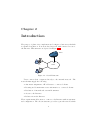

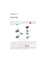
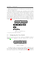


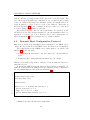
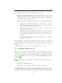
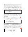
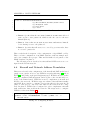
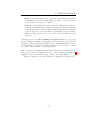


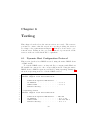


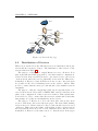
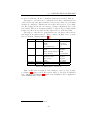

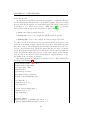
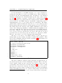
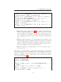
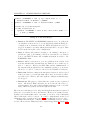
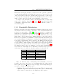
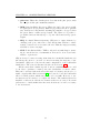

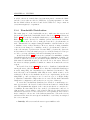
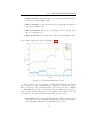


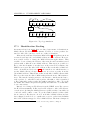
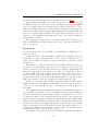
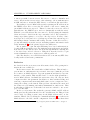
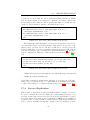
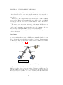
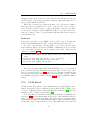
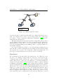
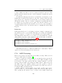
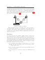


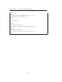


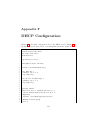
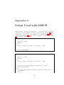


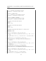
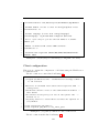
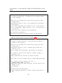
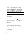
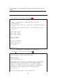
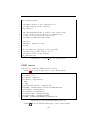
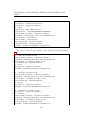
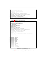


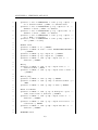
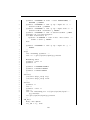
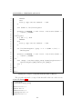
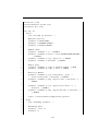


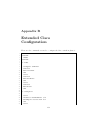
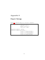

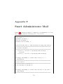


![User Manual [5.5 Mb - pdf]](http://vs1.manualzilla.com/store/data/005950654_1-5f0c3bfbdc0fa52796e7d9a416391587-150x150.png)