1
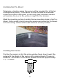
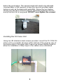
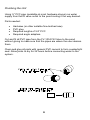
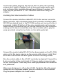
AUTOMATIC WATER LEVELING SYSTEMS
LCS-3401
Automatic Water Leveling
System
User Manual
Copyright Aquility Systems, Inc. 2010
Table of Contents
Table of Contents............................................................................... i
Safety Overview ................................................................................1
Installation.........................................................................................2
Preparing for Installation....................................................................2
Installing the Controller......................................................................3
Installing the Pro-Mount.....................................................................4
Installing the Sensor..........................................................................4
Installing the Fill Valve Unit ...............................................................5
Plumbing the Unit ..............................................................................6
Installing Interconnection Cables.......................................................7
Operation ..........................................................................................8
Adjusting Water Level................................................................8
Fill Cycle ...........................................................................................9
Alarm Condition...............................................................................10
Maintenance....................................................................................10
Troubleshooting ..............................................................................11
Overcycling .....................................................................................12
Overview ..................................................................................12
Strategy....................................................................................12
Manufacturer's Statement................................................................13
Blank Page......................................................................................14
Notes..........................................................................................15/16
Warranty .........................................................................................17
i
Safety Overview
The LCS-3401 Pond Filling System is designed to provide
the user a safe product that is easy to install and use. When installed
as described in this manual, the system presents no unsafe shock
hazards. However, altering any of the components may present an
unsafe circumstance.
Some other considerations to keep in mind during installation and
operations are as follows:
Never mount the LC-901 controller in an outdoors environment where
it will get wet. The controller and power supply are for indoor use
only.
Do not insert metal objects into sensor probes while unit is turned on.
Do not break seals on controller. Doing so may expose the user to
potentially dangerous voltages when unit is turned on and will void the
warranty.
Always mount the controller out of the reach of small children.
Always use safety equipment, such as eye protection, and dust mask
when cutting PVC piping along with other normal safety precautions.
Always carefully follow all installation instructions.
1
Installation
The LCS-3401 Automatic Pond Filling System is simple to install,
requiring simple PVC pipe installation and screw mounting the control,
fill valve and sensor. All electrical connections are done through
waterproof circular connectors for outdoor components and a single
DB9 connector to the controller. The limited plumbing that is necessary
to provide the system with filling water, requires only a hacksaw (or
other appropriate saw), PVC cement and sufficient PVC and adapters.
Preparing for Installation
Open the package and ensure that all of the components are present
and have not been damaged in shipping. Items included in the system
are:
•
•
•
•
•
•
•
•
LC-901 Controller
FV-1034 Fill Valve Module
MNT-P Pro-Mount
WC-001 15’ Control Cable
WC-002 25’ Sensor Cable
24VAC Power Supply
WLS-901 Sensor Unit
Mounting Accessory package w/Hose-MPT adapter
Identify where the FV-1034 fill valve module and the controller will be
mounted. The FV-1034 should be mounted near an outside spigot and
within 24 feet of the pond to allow connection to the sensor with the 25’
WC-002 Sensor Cable.
The LC-901 Controller needs to be located in a dry location within 14
feet of the FV-1034 to allow for connection between the two units with
the 15’ WC-001 Control Cable.
Note: Cables WC-001 and WC-002 should be laid out to determine
proper spacing for the system components when considering
where the cable will run. The WC-002 cable may follow the PVC
run to the pond for ease of installation.
2
Installing the Controller
Make sure that the power switch is in the OFF (0) position. Open the
battery compartment on the backside of the controller. Install the
battery provided. Replace battery cover. Mount controller on wall in a
dry location using the two #6 screws and template provided (Level
Waters recommends that the controller be mounted indoors, although
a well-protected patio will work).
3
Installing the Pro-Mount
Determine a location where the sensor will be mounted (try to find an
inconspicuous place.). If the sensor is to be mounted in a skimmer,
locate the surface it will mount on and verify that the sensor window
will maintain the level at the optimum height for the skimmer.
Mark the mounting surface to match the two mounting holes in the ProMount. Drill a small #4 pilot hole at the marks and screw the Pro-Mount
to the mounting surface with the #6 stainless screws provided.
Installing the Sensor
Position the sensor so that the probe window faces down toward the
water with the dimple of the sensor at the desired level of the pond
waterline. The bottom of the sensor probes should fall approximately
1-½ - 2 inches
4
below the pond edge. The sensor height will need to be adjusted
(covered later in this manual) to take into account ancillary water
systems such as fountains and waterfalls. Screw the two captive
screws into the face of the Pro-Mount alternating between the two
every third turn for a snug seat. DO NOT over-tighten the screws!
Installing the Fill Valve Unit
Using two #6 stainless-steel screws provided, mount the FV-1034 Fill
Valve unit to a suitable structure within 24 feet of the pond by way of
the screw slots in the upper tabs. Leave the screws slightly loose to
allow for installation of drip loops in the cables once connected.
5
Plumbing the Unit
Using ¾” PVC pipe (available at most hardware stores) run water
supply from the fill valve outlet to the pond routing it the way desired.
Parts needed:
•
•
•
•
Hacksaw (or other suitable fine-toothed saw)
PVC glue
Required lengths of 3/4” PVC
Required angle adapters.
Cut and fit all PVC pipe from the FV-1034 Fill Valve to the pond
without gluing to make sure that the pipes are where the user desires
them.
Clean and glue all parts with general PVC cement to form a watertight
seal. Allow joints to dry for 24 hours before connecting water to the
system.
6
Connect the water spigot to the input of the FV-1034 valve module
using a short length of garden hose (a hose reel leader works well)
and a chlorine filter (available through level Waters) if needed. The
input may be plumbed to ¾” FPT if desired rather than using the
adapter.
Installing the Interconnection Cables
Connect the sensor interface cable WC-002 to the sensor connector.
Wrap connector with vulcanizing tape. Run the sensor interface cable
WC-002 as desired back to the FV-1034 module and connect to the 4prong jack. Lightly lift bottom of the valve module and run the sensor
cable through the capture loop on the side farthest from the connector
making sure to leave a small drip loop. Secure cable with a gray tiewrap (provided) using the two holes on the cable guide tab.
Connect the control cable WC-001 to the 6-prong jack on the FV-1034
valve unit in the same manner as the sensor cable above. Install third
#6 screw in the bottom tab and tighten all valve mounting screws.
Run the control cable to the LC-901 controller as desired. Connect the
9-pin connecter to the control jack J2. Secure captive screws snugly.
Do not over-tighten! There may be a small gap between the screw tab
and jackscrew.
Make sure that power is off on the LC-901 Controller. Plug the power
connecter into the power adapter jack in the bottom of the controller.
Plug the power adapter into a wall socket.
7
Operation
Turn the power switch to the on position. The green power lamp
should light. The red light may flash and the Amber fill lamp should
light and stay lit for approximately twenty seconds. (If the amber fill
light does not light, the sensor may be below the waterline.)
Note! Depending on the level of the water at the time of power up, the unit may
goes through several fill cycles before turning off.
Adjusting Water Level
Since each pond’s water dynamic characteristics are different, the
level of the pond will vary with changes in pump cycles for fountains
and waterfalls since these units draw water in and lift it out of the pond.
If there are no pumps that lift water out of the pond (lifting pumps) and
cycle on and off over time, or if the pumps remain on constantly, the
pond’s waterline will remain somewhat constant over time. Adjusting
the WLS-901 sensor to the desired level should work well. The level
will fluctuate slightly between the beginning and end of the fill cycle.
If there are lifting pumps, however, that cycle on a schedule, the water
level will drop when the pumps are on and rise when they are off
(Pumps
8
that merely circulate water will have no effect). This will cause the
waterline to fluctuate between what we term as the quiescent (no
pumps on) and dynamic (any lifting pump on) level. The quiescent
level will be lower than immediately after a dynamic cycle where the
pumps have just turned off.
Sensor level adjustment must account for this and the installer will
need to adjust for optimal level over a period of a few days. To do so,
follow these steps:
1. Adjust the WLS-901sensor so that the bottom edge of the
probe window is between 2 and 2 ½ “from the top edge of the
pond with no lifting pumps on.
2. Observe the level of the water just after a dynamic cycle (a
lifting pump has cycled on and turned off). This is the dynamic
level.
3. Make a mark on the sensor and adjust the sensor to align the
mark to approximately 1” below the top edge of the pond.
4. Observe the waterline in both quiescent and immediately after
a dynamic cycle. Make minor adjustments to reach optimal
water level. Take care not to raise the sensor too high. This will
cause a possible overflow condition and will waste water.
Generally, 1” from the top after a dynamic cycle and
approximately 2” from the top of the pond for the quiescent
level is sufficient.
Even though a pond with lifting pumps will have a dynamic range and
a quiescent range, the quiescent range may never be observed
depending on the frequency of the lifting pump cycles.
Fill Cycle
When the water level goes below the preset level (dynamic or
quiescent), the LC-901 controller will begin a 20 second timed fill. The
amber ‘FILL’ lamp will light and remain on during the fill cycle and will
go out when the fill cycle ends. Depending on the size of the pond, the
supply water pressure and how much water is needed, multiple fill
cycles may occur.
9
Alarm Condition
The LC-901 controller provides an alarm notification in the event of
loss of sensor connectivity or loss of power. During either of these
conditions, the Red lamp will light and the piezo alarm will sound for
the following conditions:
Red
Green – Sensor Loss alarm
Red
Green – Power Loss alarm
The piezo alarm will only sound for a period of time until the battery is
exhausted. To silence the alarm and extend battery life, turn the LC901 Controller power off until problem is resolved (see
troubleshooting).
Maintenance
The LCS-3401 requires little regular maintenance. The following steps
should be taken to ensure optimum operation of the system:
Battery - The battery should be changed every six months or after a
prolonged period of alarm condition with a 9v alkaline battery.
Sensor – Periodically clean debris from probe window to maintain
optimum operation.
Over time, the sensor probes will wear due to electrolytic reactions.
This is normal and will not affect the operation of the unit. A probe that
is ¾ of its original length or moderately pitted should be replaced.
Replacements may be found at www.aquilitysystems.com or from your
favorite dealer.
Note! Most municipal areas add chemicals such as chlorine to the city water
supply, which may harm or kill any fish living in the pond if not treated properly.
Ensure that your water is suitable for fish before using the LCS-3401 or that an
appropriate filter is used. The CLF-4S may be used for all systems to filter out
chlorine for up to 1 year.
10
Troubleshooting
The LCS-3401 Automatic Pond Leveling system should maintain the
level in your pond for many worry-free years. However, if you should
experience problems with it, it may be caused by some of these
common issues that can be resolved by the user:
Pond overflows when filling
Pond will not fill
Check to make sure power is on and green lamp on
controller is lit.
Check for debris on sensor and clean per instructions
Check to ensure sensor connector has weatherproof
tape installed. Allow connector to dry if necessary and
install tape.
Sensor alarm is sounding but sensor looks ok
Readjust sensor height to lower water level
Check sensor cable and connections.
Check control cable and connections.
Power Loss/Over-cycling alarm is sounding
Check that power plug is in and plugged into the wall.
Check to verify that the pond does not have a large leak
(see over-cycling).
11
Over-cycling
Overview
The frequency that the pond fills is an indication of how much water is
being lost over time. Frequent cycling could be the indication of a leak
that could become worse as time progresses. The owner should be
aware of the pond cycling time so that, should the pond develop a
leak, they can take corrective action before it becomes too severe for
the LCS-3401 to compensate for.
Once a leak becomes larger than the flow into the pond from the LCS3401, the system will cycle repeatedly and finally trip the resetable
fuse. The problem should be corrected prior to reaching this stage.
Generally, if the pond is cycling more than a couple of times per day,
there is a leak somewhere unless there is a water replenish system in
use. The LCS-3401 will handle cycling as frequently as one every ten
minutes. After this, depending on the ambient temperature that the
controller is in, the unit will go into over-cycling alarm and will power
down.
To reset the system, the unit must be switched off, the problem
repaired and the pond refilled. This should give the unit time to reset
before it is turned on again.
Strategy
The general belief in many circles is that a pond filling system should
be turned off when a leak is detected thereby saving valuable water.
However, many pond owners that keep fish might disagree. As
expensive as fish are, using some water to save them is economical.
Therefore, the LCS-3401 will attempt to maintain level even though
there is a leak and the owner will need to remain aware of how often
the pond is filling.
12
Manufacturer’s Statement
Thank you for purchasing the Level Waters LCS-3401 Pond Filling
System. The system has taken many years of engineering and
development and it is our wish that it will provide you, the customer,
with years of trouble-free service.
As pond enthusiasts ourselves, we have found that while electronic
sensing is more expensive than float-valves, it is far more dependable
and less intrusive to the beauty of any pond because of the lower
profile of the sensing unit. Other systems have tried a similar
approach, although none have been successful in maintaining a proper
level in turbulent water, as the LCS-3401 is capable of doing.
As well, other systems do not provide a modularized system for ease
of installation. We think that you will find this feature to be superior to
other supplier’s systems that cost considerably more. The average
pond keeper will be able to install the system with ease and will never
have to worry about floats getting clogged or filling with water again.
The LCS-3401 is made for small to medium ponds and is hand
assembled from PVC material instead of molded ABS plastic. PVC
provides for better endurance in sunlight and heat and will extend the
life of the components over time than using other plastics would.
Using a single plane geometric sensor design along with delayed fill
allows the Level Waters’ filling technology to achieve an optimum level
even though the water is turbulent and can be adapted for larger
applications on a special order basis.
For more information on the LCS-3401 or custom orders visit us on the
web at www.aquilitysystems.com.
13
This Page Intentionally Left Blank
14
Notes
15
Notes
16
Warranty
Aquility Systems, Inc warrants this product to the original purchaser for
a period of one year against defects in material or workmanship when
used for normal residential purposes it is intended for. In order to
obtain a replacement unit or repair the existing unit, you must return
the complete unit, postage prepaid, to the place of purchase, or to the
Aquility Systems facility.
(6949 SW 21st Lane, Gainesville, FL 32607)
This warranty is intended to cover product defects only. Aquility
Systems, Inc. is not liable for indirect, incidental or consequential
damages in connection with the use of the Level Waters product
covered by this warranty. This warranty does not cover any cost or
expense incurred by the purchaser in providing substitute equipment
or service during reasonable periods of malfunction or non-use of this
product, while waiting for completion of repairs under this warranty.
Some states do not allow exclusions of incidental or consequential
damages, so the above exclusions may not apply in all states. This
warranty gives you specific legal rights in your state, which vary from
state to state.
If you wish to contact Aquility Systems, Inc., please direct inquiries to:
Customer Service
Aquility Systems, Inc.
6949 SW 21st Ln.
Gainesville, FL 32607
17
LLeevveell W
Waatteerrss is a trademark
of
Aquility Systems, Inc.
6949 SW 21st Ln.
Gainesville, FL 32607
www.aquilitysystems.com