1
QMBox10 series devices:
QMBox10-16, QMBox10-32,
QMBox10-48, QMBox10-128
Technical Description and User Manual.
Revision 2.1.
1.
GENERAL INFORMATION .......................................................................................................................................2
2.
SPECIFICATIONS........................................................................................................................................................3
3.
ARCHITECTURE.........................................................................................................................................................6
4.
PRINCIPLE OF OPERATION....................................................................................................................................7
5.
ACQUISITION SYNCHRONIZATION .....................................................................................................................8
6.
CONNECTING THE DEVICE ....................................................................................................................................9
6.1.
6.2.
7.
CONNECTING THE DEVICE TO THE PC FOR THE FIRST TIME ....................................................................................10
CONNECTING TO THE OBJECT .................................................................................................................................12
SOFTWARE.................................................................................................................................................................15
7.1.
7.2.
QMLAB SOFTWARE SUITE ......................................................................................................................................15
SOFTWARE DEVELOPMENT KIT ...............................................................................................................................16
Contacts:
http://www.RTechElectronics.com
[email protected]
- Common questions
[email protected]
- Sales department
[email protected] - Technical support
1. General information
The QMBox10 series devices are multichannel ADCs with USB 2.0 interface. Depending on
their model, the devices may feature 16 to 128 differential analog inputs or from 32 to 256 singleended analog inputs.
The devices of QMBox20 series are designed for analog-to-digital conversion of signals with
0...200 kHz spectrum components. The devices may be used as multichannel oscilloscopes,
spectrum analyzers, as well as full-fledged data recorders with indefinite continuous data storage on
PC.
Features
•
Minimal “cost / number of channels” ratio alongside with the excellent metrological
characteristics;
•
Single-ended input mode permits doubling the number of channels when the use of
differential inputs is not required;
•
Communication with PC provides a possibility of simultaneous acquisition, visualization and
storage of data without gaps or recording time limits;
•
Free PC software (Windows OS) is sufficient to operate the device without any additional
calibration or programming.
QMBox10 User manual
Rev. 2.1.
2 of 16
2. Specifications
Model
QMBox10-16
QMBox10-32
QMBox10-48
QMBox10-128
Number of input
channels
16 differential /
32 singleended
32 differential /
64 singleended
48 differential /
96 singleended
64 to 128
differential / 128 to
256 single-ended
Design
Input signal range
(programmable per
channel)
Max. aggregate
throughput (all
channels)
Max. sampling rate
(one channel)
ADC resolution
± 10 V; ± 2.5 V, ± 0.625 V, ± 0.156 V
0.4 MS/s
0.8 MS/s
1.2 MS/s
0.4 MS/s
14 bits
Sensitivity
- at input range ± 2.5 V
Reference limiting error
0.7 mV
0.05 %
Typical common-mode
rejection ratio (input
signal 5 V, 10 kHz)
Typical crosstalk (for
input signal 10 kHz with
channel switching
frequency 100 kHz at
input ranges ± 10 V; ±
2.5 V, ±0.625 V)
Input overvoltage
protection:
-75 dB
-83 dB
- Permanent overvoltage (10
sec)
- Impulse (1 ms)
±15 V
PC interface
±50 V
USB 2.0
Power supply
100–240 V AC or 24 V DC
External environment
Dimensions, mm
QMBox10 User manual
1.6 – 3.2 MS/s
from +5°С up to +55°С with relative moisture from 5% up to 90%
140x190x40
140x190x60
Rev. 2.1.
140x190x80
260x260x160
3 of 16
Figures below show typical characteristics of a QMBox10 device: Harmonic distortion; noise in the
½ fADC band; the graph of Crosstalk dependency towards channel switching frequency.
Noise in the ½ fADC band (fADC = 400 kHz)
Harmonic distortion. Input signal - sine-wave 10 kHz, 3V. fADC = 400 kHz.
QMBox10 User manual
Rev. 2.1.
4 of 16
0
-10
Crosstalk, dB
-20
-30
x1
x4
x16
x64
-40
-50
-60
-70
-80
-90
0
100
200
300
400
Frequencies of channel switching, kHz
Crosstalk dependency towards channel switching frequency.
QMBox10 User manual
Rev. 2.1.
5 of 16
3. Architecture
The basic components of QMBox10 devices are 16-channel QMS10 ADC modules that are
installed into one case. Depending on the number of modules installed, a QMBox10 device can have
1-, 2-, 3- or 8-module configurations, thus, different models of the device differ in the number of input
channels.
Model
Number of the
QMS10 modules
installed
Number of input
channels (diff. /
single ended)
Dimensions
QMBox10-16
QMBox10-32
QMBox10-48
QMBox10-128
1
2
3
4 to 8
16/32
32/64
48/96
64/128 to 128/256
140x190x40 mm
140x190x60 mm
140x190x80 mm
260x260x160 mm
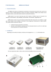
The two-module device QMBox10-32 is used to demonstrate QMBox10 internal construction:
A – the assembled device; В – the same device with the cover removed;
1 – Bottom shell
2, 3 – QMS10 ADC modules – 2 pieces
4 – Interface board that controls operation of the modules and ensures connection of the device to the
computer via USB
5 – Interconnect board that ensures electric connection of the modules to the interface board.
Inside the case the QMS10 modules are plugged into the slots of the interconnect board. This
board joins the modules into a single device and ensures electric connection of the modules to the
interface USB board. The interface board controls operation of the modules and ensures connection
of the device to the PC via USB.
*
This scalable modular architecture allows to combine modules of different types (ADC, DAC, Discrete
I/O, etc.) in a single device. These modules can be combined in one device in any configuration. For
detailed information about Combined devices, see
http://www.rtechelectronics.com/products/qmbox/index.php
QMBox10 User manual
Rev. 2.1.
6 of 16
4. Principle of operation
The QMBox10 series devices operate under PC control (OS Windows) via USB connection. The
software supplied with QMBox10 devices performs stream input of data from the ADC to the PC
memory, its processing and further visualization on the display as well as saving to the PC hard disk:
QMBox
hardware
PC
USB
Object
Analog
signals
Data processing
Digitizing
Data visualization
Data saving
Before starting work the configuration is performed by means of the software – the operation
parameters of the device are set: sampling rate, the number of channels in use, etc.1
After this the device is started, i.e. the data transfer session is launched.
During the data transfer session the QMBox10 device digitizes input analog signals at a preset
rate and sends the data through the interface board to the computer via USB. In the PC the data is
put to a circular buffer in RAM. During the buffer filling, the data is taken from it by the application
software for further processing, visualization and saving to the hard disk. Since the software takes
data from the buffer at a rate higher than the rate of its receipt from the device, the data transfer
session can last for however long, and data from the device is received by the computer without gaps.
Thus, the device can be used as a full-fledged data recorder without record time limits.
1
It should be taken into consideration that the overall rate of all the channels in use cannot be arbitrarily high. For example,
the “Max aggregate throughput” parameter of the QMBox10-48 device = 1.2 MS/s (see Technical Specifications). This
means that one can use all the 48 channels of the device with the sampling rate not higher than (1.2 / 48) = 25 kHz; or 6
channels with the rate not higher than (1.2 / 6) = 200 kHz; or 3 channels with the maximum possible rate (1.2 / 3) = 400 kHz.
QMBox10 User manual
Rev. 2.1.
7 of 16
5. Acquisition synchronization
All the modules installed in the device are clocked by the same generator on the interface board.
That is why in the course of work the modules of the device are precisely synchronised with each
other.
However, sometimes it is necessary not only to synchronize the modules with each other, but to
precisely time the entire device to be started by a certain external event.
By default the device starts the acquisition since after issuing the command “Start” from a PC.
This command can be executed within a few milliseconds. The exact execution time of this command
under OS Windows (that is not a real-time OS) is impossible to be learnt in advance. For the cases
when it is necessary to bind the start of the data acquisition to any external event with high precision
one can use the external start synchronization mode. In this mode for the beginning of the acquisition
after the issuing the “Start” command it is necessary to give a negative digital pulse (logical “1” - “0” “1”) to the "SYN" contact of the device. The data acquisition begins right after negative pulse edge
(logical “1” to “0”) arrives. The duration of the SYN pulse (i.e. of the logic “0”) must be at least 50 ns.
The “SYN” line has an internal pull-up resistor, so one can just short the “SYN” line to “ground” to
generate the required pulse.
Switching between start synchronization modes of data acquisition is software-selectable.
QMBox10 User manual
Rev. 2.1.
8 of 16
6. Connecting the device
The figure shows the rear panel of a QMBox10 device:
“Link” LED
USB Port
Power Supply Port
“Link” LED — turns on when the device is connected to USB and signals that the USB port of the
computer has identified the device correctly.
USB port — type B. A standard connector for connecting the device to the PC via USB with an
standard USB A-B cable.
Power Supply Port — it is used for supplying power from an external supply included in the
delivery set.
The procedure of connecting the QMBox series devices is as follows:
1.
Connect the power supply from the delivery set of the device to the Power Supply Port of
the device.
2.
Connect the power supply from the delivery set of the device to AC network.
3.
Connect the device to the PC via a USB cable. At this the “Link” LED should turn on. When
the device is connected for the first time, driver installation might be required. For further
information see Connecting the device to the PC for the first time.
4.
Connect the signal sources to the device — see Connecting to the object.
The procedure of disconnecting the the QMBox series devices is as follows:
1. Disconnect the object (signal sources) from the device.
2. Disconnect the device from the PC.
3. Disconnect the power supply from the AC network.
4. Disconnect the power supply from the device.
QMBox10 User manual
Rev. 2.1.
9 of 16
6.1.
Connecting the device to the PC for the first time
When the QMBox series device is connected to a Windows PC for the first time, it is necessary to
specify the location of the device driver.
Before connecting the device to the PC for the first time you should first insert the included CD
into the CD-ROM drive of your PC and only then connect the device to the PC via a USB cable.
As a rule, having detected a new device, Windows starts the Found New Hardware Wizard. In this
case you should follow its instructions, choosing not to go to the Windows Update site and specifying
the “\DRV” folder on the included CD as the location of the driver.
Windows might not start the Found New Hardware Wizard automatically, returning a driver error
message in the notification area (in the right bottom corner of the screen):
In this case you should start the Device Manager. In different Windows OS versions the Device
Manager is started differently. For example, in Windows 7 it can be started by right-clicking the
Computer icon, then – Properties, and then – Device Manager.
In the Device Manager QMBox device will appear as Unknown device. You should right-click on it
and select “Update Driver Software”:
QMBox10 User manual
Rev. 2.1.
10 of 16
After this the Found New Hardware Wizard will start up:
You should select “Browse my computer for driver software” and specify the “\DRV” folder on the
included CD as the location of the driver.
Then you should follow the instructions of the Wizard. Once the driver is successfully installed, the
“RT USB30K QMSystem Crate Controller USB” device should appear in the Device Manager:
This means that the device’s Interface board has been identified correctly by the PC, the driver is
installed and the device is ready to work.
Afterwards, when the QMBox device is connected to another USB port of the PC, Windows might
once again detect the QMBox device as “unknown device”. In this case you will have to repeat the
driver installation procedure as described above.
QMBox10 User manual
Rev. 2.1.
11 of 16
6.2.
Connecting to the object
The figure shows the front panel of a QMBox10 device (QMBox10-32 model, consists of 2 QMS10
modules):
37
19
20
1
37
19
20
1
Input Ports
Every QMS10 module which is a part of the QMBox10 device has its own input port for the signals
connection.
The input port of the QMS10 module is described in the table, where Хn —non-inverting, and Yn
— inverting inputs of the differential channel n; NC — the pin is reserved.
Pin
num.
1
2
3
4
5
6
7
8
9
10
11
12
13
14
15
16
17
18
19
Description
+15 V (analog supply) output
-15 V (analog supply) output
AGND – Analog ground 3
Y16 input
Y15 input
Y14 input
Y13 input
Y12 input
Y11 input
Y10 input
Y9 input
Y8 input
Y7 input
Y6 input
Y5 input
Y4 input
Y3 input
Y2 input
Y1 input
Pin
num.
20
21
22
23
24
25
26
27
28
29
30
31
32
33
34
35
36
37
Description
SYN – synchronization input2
AGND32–ground for single-ended mode
X16 input
X15 input
X14 input
X13 input
X12 input
X11 input
X10 input
X9 input
X8 input
X7 input
X6 input
X5 input
X4 input
X3 input
X2 input
X1 input
2
See Acquisition synchronization. Allowable potential on the SYN input is 0… 3,5 V relative to the ground
(contacts 11, 28).
3
Analog ground is connected to USB ground inside the device.
QMBox10 User manual
Rev. 2.1.
12 of 16
The correct connection of the sources of analog signal is the most important condition of the
correct operation of acquisition system which allows to avoid a lot of problems during the device
operation. During the connection of the sources of analog signal to the device it is necessary to keep
to the following recommendations:
1.
2.
3.
4.
Differential connection presupposes measuring voltage difference between the inverting
and non-inverting inputs of the channel, i.e. differential voltage. However, it is necessary to
remember that the voltage in relation to the analog ground of the device on both
inputs (common-mode voltage) should not be higher than the acceptable input
signal range.
Correct connection of a signal to the differential input is always a three-wire connection. It
is necessary to separate signal wires connected to a high-impedance input from the
common ground wire. Thus, circuit of high current through signal wires, which reduces
measurement accuracy, is eliminated.
When several signal sources are connected to the device, it is advisable that their common
wires connect at one point only, on the AGND pin of the input port. This will eliminate
formation of “ground loops” that are a source of extra noise.
The unused analog inputs should be grounded — i.e. just to be connected with AGND pins
of the input port. Unused digital inputs could be left disconnected.
On the scheme there are the examples of the correct connection of 1-phase and 2-phase
(differential) signal sources to the device. Note that even single-phase signal sources should be
connected to a differential input with three wires!
The single-phase signal
sources
The differential signal
sources
X1
Y1
X1
Y1
...
...
Xn
Xn
Yn
Yn
AGND
AGND
Differential connection of a signal source reduces the level of common-mode noise. Besides,
differential inputs allow connecting signal sources so that currents of signal circuits do not flow
through a single wire, which increases measurement accuracy.
QMBox10 User manual
Rev. 2.1.
13 of 16
Single-ended input mode permits doubling the number of channels when the use of differential
inputs is not required.
On the scheme there is the example of the correct connection of 1-phase signal sources to the
device in “single-ended” mode:
The single-phase signal sources
in “single-ended” mode
+
-
X1
Y1
...
+
-
Xn
Yn
AGND32
AGND
QMBox10 User manual
Rev. 2.1.
14 of 16
7. Software
Software of the QMBox10 devices consists of the following components:
- QMLab software suite
- Software development kit (SDK package)
7.1.
QMLab software suite
The QMLab software suite is a universal software tool for working with QMBox devices. It allows
performing most standard tasks within measurement automation.
The QMLab suite allows you to start work immediately after the device is connected: acquire,
process, visualize and save the already calibrated data converted to the required measurement units
without help of programmers or metrologists.
The QMLab suite includes:
• data recorder;
• oscilloscope;
• spectrum analyzer;
• primary data processing unit
Primary data processing can include calibration, averaging, calculation of the signal rate of
change, etc.
For further processing data is saved in standard text and binary formats suitable for conventional
and specialized data processors (Excel, MathLAB, Cool Edit pro, etc.).
A detailed description of the QMLab suite is given in the “QMLab User Manual” document that
can be found on the site www.RTechElectronics.com and on the CD supplied with the device.
QMBox10 User manual
Rev. 2.1.
15 of 16
7.2.
Software development kit
Apart from the complete QMLab software suite, the QMBox10 delivery set includes an SDK
package, which is software and documentation designed for users who would like to create their own
applications for working with the device. This software consists of function libraries (API) and
examples of software development.
The user has a possibility to create full-blown applications using just a limited number of library
functions. These library functions are written so that even an inexperienced programmer who is not
well-versed in multithreaded and object-oriented programming can work with the device. A more
detailed description of the software development kit is given in the “QMBox Programming Guide”
document that can be found on the site www.RTechElectronics.com and on the CD supplied with the
device.
QMBox10 User manual
Rev. 2.1.
16 of 16