1
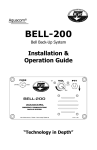
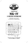
MK-7 BUDDY-LINE
Two-Diver Intercom
User Guide
“Technology in Depth”
- NOTICE This manual and the information contained herein are provided for use as a maintenance and operation guide. No license or rights to manufacture, produce, and/or
sell either the manual or articles described herein are given. Undersea Systems
International, Inc., dba Ocean Technology Systems, reserves the right to change
specifications without notice. It is recommended that all users read and fully understand this manual before using the MK-7 Buddy-Line.
All statements, technical information, and recommendations herein are based on
tests we believe to be reliable, but the accuracy or completeness thereof is not
guaranteed; and the following is made in lieu of all warranties, expressed or implied, including the implied warranties of merchantability and fitness for purpose:
Seller’s and Manufacturer’s only obligation shall be to replace such quantity of the
product proved to be defective. Before using, the user shall determine the suitability of the product for intended use, and the user assumes all risk and liability whatsoever in connection therewith. Neither Seller nor Manufacturer shall be liable
either in tort or in contract for any loss or damage—direct, incidental, or consequential—arising from the use of or the inability to use the product. No statement
or recommendation not contained herein shall have any force or effect unless it is
in an agreement signed by officers of the Seller and Manufacturer.
- IMPORTANT SAFETY NOTICE (Please read before using product.)
It is absolutely essential that all divers are properly trained and equipped and
fully understand this user’s manual before attempting to use the Aquacom®
MK-7 Buddy-Line.
While the Aquacom® MK-7 Buddy-Line provides divers good underwater communications, it does not change or eliminate the potential hazards of diving!
Refer to the Library page of our Web site, www.oceantechnologysytems.com,
for a list of any changes made to this manual since its publication.
Ocean Technology Systems - 3133 W. Harvard St., Santa Ana, CA 92704, USA
Telephone (714) 754-7848 - Toll-free (800) 550-1984 - Fax (714) 966-1639
© Copyright 2003, 2006 by Ocean Technology Systems. All rights reserved.
Specifications are subject to change without prior notice.
P/N 506018-000 (rev. C)
i
TABLE OF CONTENTS
Section
1
2
3
Title
Page
Introduction ...................................................................................... 1
Specifications ................................................................................... 2
Functions & Features ....................................................................... 3
3.1 Functions ............................................................................... 3
3.2 Features ................................................................................. 4
4
Operation .......................................................................................... 6
4.1 Setup for the Tender .............................................................. 6
4.2 Setup for the Diver(s) ............................................................ 6
5
Batteries & Charging ...................................................................... 10
6
Troubleshooting ............................................................................. 11
7
Maintenance ................................................................................... 12
8
Helpful Hints .................................................................................. 13
Warranty Information ..................................................................................... 14
Important Safety Notes ..............................................................i, 3–4, 8, 12, 13
SECTION 1
INTRODUCTION
Congratulations! You have just purchased the finest, state-of-the-art hard-wire intercom in the world. Your new MK-7 Buddy-Line two-diver air intercom represents state-of-the-art technology and innovation—the choice of discriminating divers
throughout the world. Please take the time to read this user guide. With proper care
and use, your Ocean Technology Systems product will provide you with the ultimate in high-quality communications and reliability.
The MK-7 Buddy-Line is a compact, self-contained two-diver air intercom providing clear communications between the operator and diver(s). The MK-7 BuddyLine offers four-wire (round-robin or open-microphone) type communications.
This manual will cover specifications, operating instructions, four-wire communications, batteries and charging, helpful hints, and warranty information.
These guidelines and illustrations are presented to assist you. If you need additional information, do not hesitate to confer with your local Ocean Technology
Systems (OTS) dealer or representative. If you require service, contact us:
Ocean Technology Systems
3133 W. Harvard Street, Santa Ana, California, 92704 USA
Toll-Free: (800) 550-1984 • Tel.: (714) 754-7848 • Fax: (714) 966-1639
E-mail: [email protected]
World Wide Web: http://www.oceantechnologysystems.com
1
SECTION 2
SPECIFICATIONS
Input Voltage:
12 VDC
Input Current:
600 mA peak
Idle Current:
30 mA
Frequency Response:
600 Hz to 10 kHz
Microphone Type:
Dynamic
Power Output:
2 watts RMS
Battery Types:
Eight AA alkaline batteries
One RB-11 NiMH rechargeable battery pack
Battery Life:
12 hours using eight AA alkaline batteries
Battery Chargers:
RC-16 (p/n 900289-000): 120 VAC input; 14.7 VDC, 170
mA output
RC-16i (p/n 900289-001): 90–260 VAC input; 24 VDC,
170 mA output
(Charging time: 14 hours)
Housing:
Injection-molded, high-impact plastic
Size:
Height: 6.750 inches from bottom to top of connector
Width: 4.250 inches from latch to latch
Depth: 2.750 inches from front knob to rear buckle
Weight:
1.0 pounds, without batteries
ComRope Length:
Up to 1200 feet
ComRope:
Nylon, static Kernmantle rope specially designed with two
18-AWG and two 24-AWG wires manufactured in the center. Breaking point approximately 3050 lbs. for the rope
and 1200 lbs. for the communication wires.
2
SECTION 3
FUNCTIONS & FEATURES
3.1
FUNCTIONS
The MK-7 Buddy-Line hard-wire system utilizes the “four-wire” approach. It is a
closed loop comparable to a telephone system. A typical hard-wire system consists of a surface intercom, a headset with a boom microphone, a ComRope (set
up for four wires, shielded or true spiral four), a diver microphone-earphone assembly, a mask microphone, and some sort of diving mask with accommodations
for a microphone. The Interspiro Divator MKII “AGA” full-face mask (FFM) is
what most professionals prefer, according to our statistics. A hard-wire system
requires a physical connection (i.e., umbilical/ComRope) between the listener and
talker. The signal travels over the communication ComRope.
Most hard-wire intercoms can be configured for either two- or four-wire operations. Four-wire communications is defined as a duplex communication route.
Two wires provide the uplink signal path, and two additional wires provide the
downlink path. Thus everyone can be online simultaneously (similarly to a telephone conference call). Since you never cut off the diver while talking, as is the
case with a two-wire system, the four-wire system is the safer of the two configurations. Due to the increased efficiency achieved with a four-wire system (duplex)
and its simplicity of use, the MK-7 is designed for four-wire operation only.
The standard MK-7 configuration functions as follows: After the system is powered up and all connections are properly made, the tender’s speech is picked up by
the boom microphone located on the headset. The voice is amplified by the upper
electronics module and routed through the ComRope. Connected to the ComRope
at the diver’s end is the earphone-microphone assembly (typically an EMA-2 for
the Interspiro FFM). The tender’s speech is reproduced by the earphone part of
the EM cable. When the diver speaks, his voice is picked up by the mask microphone located inside the mask being used. The voice is routed through the
ComRope, received by the upper electronic module, amplified, and then routed to
the tender’s headset. If a second diver is on-line, he will hear and talk as well in
the same manner. The volume of the tender and diver(s) is controlled by separate
volume controls on the outside of the upper electronics module.
- IMPORTANT SAFETY NOTES It is extremely important that the divers are dressed out in a manner that will
strain-relieve the ComRope. Commercial dive schools typically instruct students
to have the ComRope tethered to the diver’s harness or buoyancy compensator
with a quick release. If someone pulls on the ComRope and the diver loses
control of the ComRope, the pull is on the harness, not on the diver’s mask.
This setup prevents accidental removal of the diver’s mask.
3
Additionally, the divers should be dressed out to allow a quick disconnect from
the ComRope to allow for a situation where a diver must free himself from the
ComRope.
In the event divers and the surface tender lose voice communications, both
should have in place a back-up rope-pull system for communication. See Table
1 (p. 9) for the line-pull system recommended by Ocean Technology Systems.
3.2
FEATURES
The following are the item numbers and descriptions for Figures 1, 2 (p. 5), and
3 (p. 7):
1. Headset with boom microphone
2. Noise-canceling boom microphone
3. Female Amp connector
4. Record-out plug (male mini, line level)
5. Small o-ring
6. Male Amp connector
7. Gripper ring
8. Female Amp connector (for ComRope)
9. Upper electronics module
10. Tender volume control
11. Diver 1 and Diver 2 volume controls
12. Housing’s large o-ring
13. Battery snap
14. Eight-cell battery holder (SP-8)
15. Stainless steel latch
16. Lower housing (battery compartment)
17. Male Amp connector (ComRope)
18. ComRope
19. Hi-Use® connector (goes to ComRope)
20. Hi-Use® connector (goes to diving
mask)
21. EMA-2 ear.-mic. assembly for AGA
See Figure 3, Page 7
22. Dual earphones of EMA-2
23. Hot-Mic® microphone element
24. Hi-Use® connector (connects to EMA-2)
Note: The ComRope can be set up for many types of diving masks and/or
earphone-microphone assemblies. If you are not sure what to order, consult
an OTS dealer or OTS directly for the configuration you require.
4
EXPLODED VIEW OF MK-7 BUDDY-LINE SYSTEM
FIGURE 1: MK-7 Buddy-Line
FIGURE 2: ComRope & EMA-2 assemblies
5
SECTION 4
OPERATION
Before operating the MK-7, make certain the batteries are fresh or fully charged
(see Section 5, Batteries & Charging). Ensure that all o-rings are in place and free
of debris or foreign matter. Verify that all connections are securely fastened. Ensure the divers are dressed in such a manner that the umbilical/ComRope will not
snag. These procedures should be performed before each dive.
After you have completed the above steps, proceed as follows:
4.1
SETUP FOR THE TENDER
4.1.1
Place the headset with boom microphone on your head so the two earphones are comfortably over your ears and the boom microphone is within
1/4 inch of your lips.
4.1.2
Connect the headset’s Amp connector to the upper electronics module’s
Amp connector (Fig. 1, #3 & 6).
4.1.3
Locate the Amp connector on the ComRope, and mate it to the Amp
connector located on the top of the electronics module (Fig. 1, #8 and
Fig. 2, #17). If there is a second diver, do the same for his connection.
4.1.4
Secure the MK-7 to your belt (or wherever is most comfortable) by using
the belt clip located on the back of the upper module.
Note: We recommend that the MK-7 main module have some sort of strain
relief at the tender’s end to keep the diver and/or ComRope from putting excess
strain on the connectors. Excess strain on the connectors would cause damage
to the MK-7 and/or loss of communications.
4.2
SETUP FOR THE DIVER(S)
4.2.1
Although the MK-7 Buddy-Line can be used with various full-face or
mouth masks, the mask most commonly chosen is the Interspiro Divator
MKII (“AGA”) full-face mask (FFM). The following are the setup procedures, if you have an AGA FFM. You should have already connected
the headset and ComRopes if you are following this manual (see Section
4.1, Setup for the Tender). We are also assuming you ordered and have
the ComRope set up for four-wire communications with a male Amp
connector on one end and a Hi-Use® connector on the other end.
4.2.2.
The AGA FFM should already have the EMA-2 earphone-microphone
assembly installed. If not, install it per the installation instruction sheet
provided with the EMA-2.
4.2.3.
Locate the Hi-Use® connector on the ComRope, and connect it to the HiUse® connector on the EMA-2. Ensure the Hi-Use® connectors are free
6
of debris and lightly lubricated with a high-grade silicone grease.
4.2.4
Strain-relieve the ComRope in two places on the diver’s end. The first
point should have some sort of “D-ring” heavily taped or tied about 4
feet from the Hi-Use® connector. This “D-ring” will be clipped onto the
diver’s harness or buoyancy compensator via a carabiner or some goodquality quick-disconnector. This connection will help prevent the
ComRope from pulling on the diver’s full-face mask (Figure 3).
4.2.5
The diver should tie the ComRope, making a hand loop about 6 inches in
diameter about 10 feet from the Hi-Use® connector (Figure 3). The diver
will now be secured to his harness or buoyancy compensator and have a
hand-hold he should hold during the dive. The diver should have control
of the ComRope throughout the dive. He should feel what is going on,
giving topside directions when slack needs to be taken up or when more
rope needs to be paid out. If the diver lets go of the hand-hold, the
carabiner–D-ring combination will absorb the tension. In the event the
diver must break lose of the ComRope totally (i.e., in an emergency), the
diver should let go of the ComRope hand-hold and unsnap the device
holding the D-ring. The diver then should let topside know what is going
on before he detaches the Hi-Use® connectors. The diver then should
proceed directly to the surface and reestablish communications (see the
notes on page 8).
4.2.6.
The tender should ensure the ComRope on his end is also strain-relieved
in some manner. This will prevent the diver or topside tender from pulling on the connections made on the MK-7 Buddy-Line electronics module.
Note: See p. 4 (in Section 3.2, Features)
for the item descriptions.
FIGURE 3: Recommended Setup of the Diver ComRope
7
4.2.7
After all connections are made, you can test the system. Have the diver(s)
don the full-face mask. The tender will don the headset with boom microphone. The boom microphone should be positioned 1/4 inch from the
tender’s lips (keep the microphone as dry as possible).
The MK-7 Buddy-Line will power up the moment the headset and boom microphone are connected. There is no on/off switch. As long as the headset is plugged
in, the MK-7 will be on and drawing power.
The tender controls all volumes. The volume control labeled “Tender” controls
the volume of the tender’s voice to both divers. The individual volume controls
labeled “Divers” control what the tender hears from each diver. The tender should
adjust all volumes a little at a time until everyone can hear well. Rotating any
control clockwise brings the volume up. Counterclockwise rotation brings the
volume down.
- NOTE 1.
If the diver is set up properly, the tender’s pulling on the ComRope should
pull on the diver’s hand loop first. If the diver is not holding the hand loop,
the strain should go to the belt “D-ring,” not the diver’s full-face mask or
diver’s earphone-microphone assembly.
Ensure the diver is dressed out such that no unnecessary loops that can
entangle him are present.
2.
Excessive volume will cause distortion and hinder communications. Adjust
all volumes slowly until everyone hears clearly. A good rule to follow is
“Less volume is better than too much noise.”
- IMPORTANT SAFETY NOTES -
1.
The diver should be dressed in such a manner that he can disconnect from
the ComRope and from the earphone-microphone assembly. If it becomes
necessary to make an emergency ascent, if the diver has to break voice
communications, and if line pulls cannot be established, the diver should
surface and establish communications as soon as possible.
2.
We do not recommend you rely solely on MK-7 Buddy-Line voice communications. A back-up safeguard, such as line pulls, should be established
and practiced (Table 1).
- NO POWER! -
If you connect the headset with boom microphone and the MK-7 does not power
up, verify the batteries are fresh (new) or fully charged and that the battery
snap is connected.
8
Table 1: Recommended Line-Pull Signals
Source: U.S. Navy Diving Manual
From Te nde r to Dive r
Se arching Signals (Without Circling Line )
1 Pull
"Are you all right?" When diver is
descending, one pull means "Stop."
2 Pulls
"Going Down." During ascent, two
pulls mean "You have come up too far; 1 Pull
go back down until we stop you."
"Stop and search where you are."
3 Pulls
"Stand by to come up."
2 Pulls
"Move directly away from the tender if
given slack; move toward the tender if
strain is taken on the life line."
4 Pulls
"Come up."
3 Pulls
"Face your umbilical, take a strain,
move right."
2- 1 Pulls
"I understand" or "Talk to me."
4 Pulls
"Face your umbilical, take a strain,
move left."
3- 2 Pulls
"Ventilate."
4- 3 Pulls
"Circulate."
7 Pulls
From Dive r to Te nde r
"Go on (or off) searching signals."
Se arching Signals (With Circling Line )
1 Pull
"I am all right." When descending, one
pull means "Stop" or "I am on the
bottom."
7 Pulls
Same
2 Pulls
"Lower" or "Give me slack."
1 Pull
Same
3 Pulls
"Take up my slack."
2 Pulls
"Move away from the weight."
4 Pulls
"Haul me up."
3 Pulls
"Face the weight and go right."
2- 1 Pulls
"I understand" or "Talk to me."
4 Pulls
"Face the weight and go left."
3- 2 Pulls
"More air."
4- 3 Pulls
"Less air."
Spe cial Signals from the Dive r
Eme rge ncy Signals from the Dive r
1- 2- 3 Pulls
"Send me a square mark."
2- 2- 2 Pulls
"I am fouled and need the assistance of
another diver."
5 Pulls
"Send me a line."
3- 3- 3 Pulls
"I am fouled but can clear myself."
2- 1- 2 Pulls
"Send me a slate."
4- 4- 4 Pulls
"Haul me up immediately."
All e me rge ncy s ignals s hould be ans we re d as give n e xce pt 4-4-4.
9
SECTION 5
BATTERIES & CHARGING
With the MK-7 Buddy-Line is provided an SP-8 eight-cell AA battery holder located in the lower housing (Fig. 1, #14, on p. 5). If you use alkaline instead of
rechargeable batteries, install the eight AA alkaline batteries as follows:
1.
2.
3.
4.
5.
6.
7.
8.
Locate the latches on the sides of the lower housing (Fig. 1, #15, on p. 5). Pull
up on the latches simultaneously.
Separate the upper and lower modules while being careful not to damage the
battery snaps, wires, or o-ring (Fig. 1, #12 & 13).
Remove the SP-8 eight-cell battery holder (Fig. 1, #14) and install eight fresh,
1.5-volt alkaline AA batteries per the diagram on the SP-8.
Carefully connect the wire harness connector (Fig. 1, #13) to the SP-8 battery
holder. Verify that both spring-type connectors mate firmly and that you have
not accidently bent the connectors.
Verify that the o-ring (Fig. 1, #12) is in place, lightly lubricated with a highgrade silicone grease, and free of debris.
Insert the SP-8 battery holder into the lower housing. Carefully mate the upper
and lower housings together. Ensure that you do not pinch any wires and that
nothing is on the o-ring or mating surface.
Connect the latches from the lower housing to the upper strikes. Pull down the
latches simultaneously until fully down. This will spring-load the upper and
lower assemblies.
Look all around the MK-7 to verify the upper and lower assemblies appear
evenly attached with no high spots.
The RB-11 nickel-metal hydride (NiMH) rechargeable battery pack is available from Ocean Technology Systems or your local OTS dealer as an alternative to
alkaline batteries. The RB-11 is recharged outside the housing. To remove and
replace the RB-11 battery pack, follow the same procedure (above, #1–8) as for the
alkaline batteries but with the RB-11 instead of the SP-8 alkaline battery holder.
Recharging the batteries is a simple process. You will need an RC-16 (if in the
U.S.) or RC-16i (if outside the U.S.) battery charger, available from OTS or your
local OTS dealer. Connect the battery snaps of the charger and the RB-11 battery
pack. Plug the power input cord of the charger into an AC power outlet, 120 VAC
50 Hz with the RC-16 or 90–260 VAC 50/60 Hz with the RC-16i. Charge the RB11 for up to 14 hours, but no longer than that to avoid overheating the battery pack.
Note: The battery you receive may have upgraded specifications from what is stated
in this manual. Due to advancing battery technologies, we continually upgrade
our batteries and chargers. Contact OTS or your local OTS dealer for information
about the latest available battery and charger.
10
SECTION 6
TROUBLESHOOTING
Problem: Corrosion buildup on the connectors.
PC
R
Possible Cause and Remedy
Failure to wash and lubricate connectors after use in salt water.
Remove salt water residue or corrosion from the unit by wiping it with a
cloth saturated in warm freshwater (use detergent if necessary). Periodically check the connectors to ensure they are clean and lightly lubricated
with a high-grade silicone grease.
Problem: Poor or no communications.
PC
R.
PC
R
PC
R
PC
R
PC
R
PC
R
Possible Cause and Remedy
Batteries are defective or dead.
Replace alkaline AA batteries with fresh ones. If using a rechargeable
battery pack, recharge it.
Connectors are not properly connected or are damaged.
Clean and check all connectors. Replace damaged ones.
Headset with boom microphone is not plugged in.
Connect headset; unit should power up.
Diver(s) cannot hear topside, but topside can hear divers.
Check topside microphone and make sure the tender volume is turned on
and the microphone is about 1/4 inch from the tender’s lips.
Diver(s) can hear topside, but topside cannot hear the divers.
Check all connections. Check the diver’s microphone. Verify the diver’s
volume controls are turned up.
Tender and divers hear light music over the intercom.
This happens if you are using an unshielded umbilical and are close to a
transmitting station. The only way to solve this problem is to change to a
shielded ComRope.
Problem: A strong but distorted signal is received.
PC
R
PC
R
Possible Cause and Remedy
You are speaking too loudly into the microphone.
Speak with more moderate volume, slowly and distinctly.
Your volume controls are set at too high a level.
Slowly adjust your volumes as to not overdrive the system.
11
SECTION 7
MAINTENANCE
The MK-7 Buddy-Line is virtually maintenance free and should give you great
service during the life of the unit. The following are recommended service tasks:
1) Try to keep the headset with boom microphone as dry as possible.
2) Do not store the ComRope in a sealed container without drying it first. It will
grow mold if not dry.
3) If the ComRope was used in salt water, soak it in freshwater for about five
minutes before drying.
4) If salt water gets onto the headset and/or MK-7, wipe it with a clean cloth and
freshwater. Warm water and a mild soap solution can be used. Wipe it off with
freshwater before drying.
5) Disconnect all connectors when storing.
6) Lightly lubricate the Hi-Use® connector with a high-grade silicone grease.
7) If the MK-7 is not going to be used for a long period of time, the batteries
should be removed.
- PLEASE NOTE Although the MK-7 Buddy-Line is a ruggedly constructed piece of your diving
gear, it should be treated like an electronic piece of equipment!
! ! ! CAUTION ! ! !
Use any standard safe entry into the water, but be aware of the additional equipment you are wearing. Because the ComRope can snag on things, be aware of
obstacles in the area and avoid them. Make sure there is nothing in the water
the diver may hit upon entry.
12
SECTION 8
HELPFUL HINTS
A. All training should be conducted in a controlled environment such as a swimming pool.
B. All personnel who intend to use this system should read and fully understand
this manual and equipment before they use it.
C. Divers should be dressed in such a manner that they can disconnect quickly
from the ComRope and/or earphone-microphone assembly.
D. The ComRope should be strain-relieved at both the diver’s and tender’s ends.
It is extremely important the divers have the ComRope strain-relieved to their
harness or buoyancy compensator and not to the full-face mask.
E. The topside tender is in control of the rope topside, ensuring that it is not
getting tangled and that it is not a safety hazard for those walking about.
F.
The divers should be aware of their surroundings, making sure their ComRopes
do not become entangled.
G. When a diver must enter the water by jumping into the water, the following is
the recommended procedure: The diver should step up to the end of the pier
or edge from which he is about to jump. The ComRope will be connected to
the diver, who will be holding onto the hand loop he has made on the ComRope.
The tender should lower enough slack so as to just touch the water. The diver
looking out toward the horizon will start his giant step. As the diver steps off,
he turns to face the tender holding on to the ComRope. When he enters the
water, he should be looking at the tender.
- SAFETY NOTE If the diver plans to make a jump, it is extremely important the tender does
not forget to pull slack in the ComRope. The ComRope should barely touch
the water while still being attached to the diver. This gives the diver the amount
of rope necessary to hit the water with some slack. If there is no slack in the
rope, the diver could be seriously hurt by being hung or jarred.
13
Undersea Systems International
dba
Ocean Technology Systems
LIMITED WARRANTY
The Aquacom® MK7 Buddy-Line is fully warranted against
defects in materials and workmanship for a period of one
year from the time of purchase. Our obligation under this
warranty is limited to the replacement of any part or parts
that prove to our satisfaction to have been defective and that
have not been misused or carelessly handled. Labor is warranted for one year from time of purchase. The complete unit
and/or part must be returned to our factory, transportation
charges prepaid.
We reserve the right to decline responsibility where repairs
have been made or attempted by other than an Ocean Technology Systems factory-trained service center or properly
trained personnel. In no event shall Ocean Technology Systems be liable for consequential damages.
Ocean Technology Systems
3133 W. Harvard St., Santa Ana, CA 92704, USA
Telephone (714) 754-7848 • Toll-Free (800) 550-1984 • Fax (714) 966-1639
www. oceantechnologysystems.com • [email protected]
© Copyright 2003, 2006 by Ocean Technology Systems. All rights reserved.
14