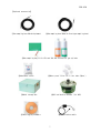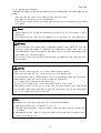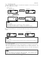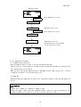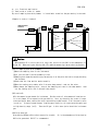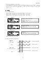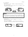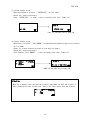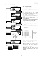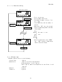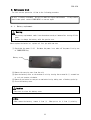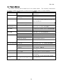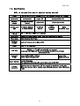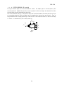
1
PT0E-0730
RIKEN PORTABLE COMBINATION GAS DETECTOR
MODEL RX−516
RX−517
OPERATION MANUAL
MARINE USE
Precaution in operation
・After reading this manual well, start to operate this instrument.
・Keep this manual where to carry out easily
・When take out this manual by use of construction work, be sure to put it
where it was.
・Do not use this instrument for no other than given purpose.
・When operate this instrument without using this manual or repair it by use of
no other parts than the genuine one, the safety and quality of products could
not be guaranteed. When any accident should take place by those irregular
method, we cannot assume the responsibility for it.
2-7-6 Azusawa Itabashi-ku Tokyo, 174-8744 Japan
Phone
Telex
Fax
E-Mail
: Tokyo (03) 3966-1113
: 272 2638 RKNFNE
: (03) 3558 9110 GⅢ
: [email protected]
PT0E-0730
In the beginning
It is of our great pleasure to purchase Riken portable combination gas detector model
RX-516/RX-517 this time. This instrument is an explosion-proof type portable gas
detector which is designed to measure the presence of the following gas at crude oil
tankers shown below.
RX-516
• Hydro carbon(HC)
• Oxygen(O2)
• Hydrogen sulfide(H2S)
:0-100.0%LEL/2-100.0vol% (Iso-butane cal.)
:0-25.0 vol%
:0-100.0ppm
RX-517
• Hydro carbon(HC)
• Oxygen(O2)
• Hydrogen sulfide(H2S)
:0-100.0%LEL/2-100.0vol% (Iso-butane cal.)
:0-25.0 vol%
:0-100.0ppm/0-1000ppm
This instruction manual is a guide book for operation to use and operate model
RX-516/RX-517. It is kindly requested to read and understand this content by
experienced users as well as beginners. The following headline shall be shown to carry
out the safety and effective work in this instruction manual.
Danger
This means that it gives the serious harm to the human life, body or material directly
such as touching high voltage.
Warning
This means that it gives the serious harm to the human body or material if do not
perform the operation according to the instruction manual.
Caution
This means that it gives the slight harm to the human body or material if do not perform
the operation according to the instruction manual.
* Note
This means the advice in the operation.
1
PT0E-0730
C O N T E N T S
1.Caution in operation ・・・・・・・・・・・・・・・・・・・・・・・・・・・・・ 3
2.Name of each part・・・・・・・・・・・・・・・・・・・・・・・・・・・・・・・ 4
3.Operation・・・・・・・・・・・・・・・・・・・・・・・・・・・・・・・・・・・ 8
3−1.Check item before operation・・・・・・・・・・・・・・・・・・・・・ 8
3−2.Preparation・・・・・・・・・・・・・・・・・・・・・・・・・・・・・・ 8
3−3.Start-up and end-up・・・・・・・・・・・・・・・・・・・・・・・・・・ 9
3−4.Flow monitor check・・・・・・・・・・・・・・・・・・・・・・・・・・ 10
3−5.Zero point adjustment・・・・・・・・・・・・・・・・・・・・・・・・ 10
3−6.Operational procedure・・・・・・・・・・・・・・・・・・・・・・・・ 12
3−7.Peak value mode・・・・・・・・・・・・・・・・・・・・・・・・・・・・ 13
3−8.Power pump ON/OFF・・・・・・・・・・・・・・・・・・・・・・・・・・・ 13
3−9.Operation finished・・・・・・・・・・・・・・・・・・・・・・・・・・ 14
3−10. Practical application・・・・・・・・・・・・・・・・・・・・・・・・ 15
4.Alarm・・・・・・・・・・・・・・・・・・・・・・・・・・・・・・・・・・・・ 16
4−1.Alarm display・・・・・・・・・・・・・・・・・・・・・・・・・・・・・ 16
4−2.Alarm buzzer & lamp・・・・・・・・・・・・・・・・・・・・・・・・・ 16
4−3.Trouble display・・・・・・・・・・・・・・・・・・・・・・・・・・・・ 17
5.Each function・・・・・・・・・・・・・・・・・・・・・・・・・・・・・・・・・ 19
5−1.Operation mode control・・・・・・・・・・・・・・・・・・・・・・・・ 19
5−1−1.Alarm setting・・・・・・・・・・・・・・・・・・・・・・・・・・ 20
5−1−2.Date/time setting・・・・・・・・・・・・・・・・・・・・・・・・ 21
5−2.LCD back light・・・・・・・・・・・・・・・・・・・・・・・・・・・・ 21
5−3.Data logger・・・・・・・・・・・・・・・・・・・・・・・・・・・・・・ 22
6.Maintenance check・・・・・・・・・・・・・・・・・・・・・・・・・・・・・・・ 23
6−1.Battery replacement・・・・・・・・・・・・・・・・・・・・・・・・・・ 23
6−2.Gas calibration (Span adjustment)・・・・・・・・・・・・・・・・・・・ 24
6−3.Filter replacement・・・・・・・・・・・・・・・・・・・・・・・・・・ 27
6−4.Sensor replacement・・・・・・・・・・・・・・・・・・・・・・・・・・ 27
6−5.Daily check and regular check・・・・・・・・・・・・・・・・・・・・・ 27
6−6.The replacement of parts・・・・・・・・・・・・・・・・・・・・・・・ 28
6−7.Storage or treatment not to use for a long period)・・・・・・・・・・ 29
7.Scrap of products・・・・・・・・・・・・・・・・・・・・・・・・・・・・・・ 29
8.Trouble shooting・・・・・・・・・・・・・・・・・・・・・・・・・・・・・・・ 30
9.Definition of words・・・・・・・・・・・・・・・・・・・・・・・・・・・・・・ 31
10.Specifications・・・・・・・・・・・・・・・・・・・・・・・・・・・・・・・ 32
11.Detection principle・・・・・・・・・・・・・・・・・・・・・・・・・・・・・ 33
11−1.NDIR method (Non-Dispersive Infrared)・・・・・・・・・・・・・・・・・ 33
11−2.GALVANIC CELL method・・・・・・・・・・・・・・・・・・・・・・・・・ 33
11−3.ELECTRO-CHEMICAL CELL method・・・・・・・・・・・・・・・・・・・・・ 34
RIKEN STANDARD WARRANTY・・・・・・・・・・・・・・・・・・・・・・・・・・・・・・ 35
2
PT0E-0730
1.Caution in operation
To maintain the function for safety, follow the following instruction.
Warning
・Do not modify nor change the circuit and structure etc. When modify or change, it could
not maintain the function.
・This is explosion-proof product. Battery has to be replaced in non-hazardous zone. The
battery replacement in hazardous zone shall be out of the scope for explosion-proof
product.
・This is explosion proof. Be sure to operate with carrying case on.
・Do not measure in the environment of oxidant gas presence. When measure, it may shorten
the sensor life.
・When measure under organic solvent gas presence, do it in short time and make sensor
cleaning by sucking fresh air after measurement.
Caution
・Do not drop or damage it. This is a fire instrument. When strong shock is given, the
function may be the case not to maintain. Especially, when power is on, the shock from
outside is easy to receive. So, the caution at this point is needed.
・Keep it from the direct splash of water. As this is not of drip-proof, it may cause
the trouble by splash of water.
・Do not give the electric noise such as by walkie-talkie during operation. When receive
the electric noise, it may cause the trouble of reading and instrument.
・When the atmospheric pressure and temperature are changed, it may affect the gas reading.
・When it is condensed, the normal operation is impossible.
・Be sure to mount the internal filter and filter tube.
3
PT0E-0730
2.Name of each part
①
⑥
②
③
④
⑤
GAS OUT
H2S Low・HC・O2
GAS IN
⑦
⑧
GAS OUT
H2S high
①POWER/ENTER SW
This is used for power ON/OFF and entering the figure.
②PUMP/− SW
This is used when make the pump ON/OFF and deverse the figure.
③ZERO/+SW
This is used when make zero adjustment and increase the figure.
④PEAK SW
This is used when to let the peak displayed.
⑤MODE/ESC SW
This is used when enter the set mode or cancel the input.
⑥ALARM LAMP
When trouble alarm triggers, this shall blink and light out.
⑦LCD with Back-light
This shows the gas reading.
⑧H2S gas range mode cock (for model RX-517 only)
The mode for H2S Low ⇔ H2S High can be changed over by this switch.
4
PT0E-0730
《Display of RX-516/517》
Hydro carbon「HC」
Oxygen「OXY」
RX-517
Hydrogen sulfide(High)
「H2S」
RX-516/RX-517
Hydrogen sulfide(Low)
「H2S」
*Caution
・For HC, when it goes over 100%LEL, it shall be changed to vol% automatically.
《RX-517 case》
・ H2S can be changed over by H2S gas range mode cock. (H2S High ⇔ H2S Low)
①H2S low display
②H2S high display
5
PT0E-0730
【Standard accessories】
①Carrying case with shoulder strap
②Filter tube with flow monitor and junction tube
③Gas sampling probe
④Gas sampling hose
⑤Alkaline battery
6
PT0E-0730
【Optional accessories】
①Gas sampling hose 30m with plummet
②Gas sampling hose 30m with float type sampling head
③Gas sampling bag 1L for LEL and VOL and calibration gas cylinder
⑤Absorbent cotton
⑥Water proof filter for filter tube (10pcs.)
⑦Metal storage box
⑧H2S calibration checker (for H2S)
⑨Data logging software
⑩Communication cable
7
PT0E-0730
3.Operation
3−1.Check item before operation
RX-516 or 517 instrument:
・Check that there is no damage for display unit etc.
Filter tube with flow monitor:
・Check the dirt of inside cotton filter. When it gets dirt, replace the cotton filter with
new one.
・When water drops remain, wipe it out and change it with new one.
・Check that these is no crack or damage.
・Check that these is no loose mount on the nipple.
Gas sampling hose:
・Check that there is no crack, creek or twist on the instrument.
3−2.Preparation
(1) Dry batteries are put into instrument.
(2) Put carrying case on to instrument.
(3) Connect the ①instrument(Gas inlet)+②Filter tube with flow monitor+③Sampling hose
respectively.
①
③
②
For gas sampling, 3 kinds tip formation are available and change it according to he measuring
environment.
Standard:
Sampling hose (1m) and gas sampling probe
Optional:
Sampling hose (30m) with plummet
Sampling hose with floating gas sampling head (30m)
・Connection with sampling hose
Take knurling part by fingers and pull ①arrow mark to ”→” direction. Put it to the arrow
mark ②←direction. Then, release the finger from the knurling part. Further press and
sound “tick,” and then, locked.
Knurling part
②
①
8
PT0E-0730
3−3.Start-up and end-up
When press power switch for 3 sec, the power gets on and this shall start up sequencing the
program of the voltage check, filter connection check and sensor connection check respectively.
Press power switch for 3 sec.
Date/time display
PREPARATION
Stand-by
PROBE OK?
Accessory connection check
(Display word atternately)
FILTER OK?
・Press ENTER key
ENTER key
SENSOR CHECK
【Sensor normal】
SENSOR OK
Warm up
Operation ready
【Sensor trouble】
FAIL SENSOR
WARM UP 30
WARM UP 30
STAND BY
STAND BY
Operation mode
Press POWER SW for 3 sec
Trouble sensor shall
show “……”.
Power off
GOOD − BYE
9
PT0E-0730
3−4.Flow monitor check
When the power gets ON, the pump shall start operation check that suction works properly by
filter tube with flow monitor.
Float
At normal sucking(Can see float)
Not sucking(Can not see float)
3−5.Zero point adjustment
Zero point calibration for this instrument shall be done HC, O2(Oxygen), H2S(Hydrogen
sulfide).
Caution
When make zero adjustment, proceed to do it after having fresh air sucked into instrument
for over 1 min. When make zero adjustment through the suction of gas present atmosphere,
the correct measurement can not be done and it may lead to the accident.
10
PT0E-0730
<FLOW CHART OF ZERO POINT ADJ>
ZERO MODE DISPLAY
ZERO key
・Press ZERO key for 3 sec.
HOLD KEY
・When press ENTER key, HC, O2, H2S zero adj
ESC key
Move to zero adj
shall start.
FRESH AIR?
ENTER key
for CO2 adj ESC key
ADJ ZERO OK
・Calibration
《Zero set OK》
《Zero adj fails》
FAIL ZERO
ZERO SET OK
Press for 5 sec and move to
the display.
All are OK
HC fails
*Note
・To cancel previous operation, press ESC key.
But can not cancel after press ENTER key.
《RX-517 case》
・For zero adjustment of H2S high, proceed to make zero adjustment by changing to the
display of H2S high
11
PT0E-0730
3−6.Operational procedure
Approach the sampling hose to the sampling site for measurement and leave sampling gas
sucked.
・Take care that any twist on the sampling hose can not be made.
・Stop sampling hose at the point of measurement.
・From the hose length consider the delay time and read out the reading after the reading
gets stable.
Danger
・Oxygen depletion air etc may be exhausted from gas outlet. Do not breathe in there
absolutely.
・High density gas over (LEL) may be exhausted. Do not approach fire there absolutely.
Warning
・In the place where environment temp is remarkably changed, there may be the case that
accurate oxygen measurement is impossible by temperature change. Wait until the
instrument may be used to the ambient temp (About 10 min) and start measurement after
having made zero calibration again.
・Do not use for after purpose then the measurement of combustible gas, vapor and toxic
gas mixchares.
Caution
・When suck air containing gas, do it after removing water vapours.
・When suck high temp gas, do it after being used to be ambient temp.
・Do not have water and oil sucked wrongly, the internal pump and sensor may be troubled.
・When measure, check the roaring sound of pump and flow monitor.
It is impossible to measure at pump work stop.
・Do not block the pump outlet, the reading shall show a little higher.
・When measure oxygen in inert gas for a long time, be sure to measure lower than 15% CO2
by all means. When exeed higher density than 15%, shorten the time for this measurement
as life of oxygen sensor may be shortend.
*Note
When measure the high density gas than LEL, the hung-up phenomenon.
① When measure HC by vol%, do measure it as it is.
② When make zero adjustment, remove the sampling base and supply fresh air sucked into
instrument.
③ When measure by %LEL, make air cleaning of sampling hose and start to measure after
reading goes down to zero.
12
PT0E-0730
3−7.Peak SW value mode
When press PEAK SW during operation, the peak valve from power on to the current point (HC,
H2S = MAX, O2=MIN) shall be shown.
【RX-516/517】
Peak mode
Operation mode
PEAK SW
P E A K
【RX-517】
H2S change over
H2S high display
Peak display
PEAK key
P E A K
*Note
《RX-517 case》
・In the H2S high display, the peak value of H2S is displayed.
・When changed from peak display, it changes to the operation display.
When hold and press ESC key for 3 sec during the peak value display, the peak value shall be
cleared.
Operation mode
Peak mode
ESC SW
P E A K
*注記
《RX-517 case》
All peak value is cleared on both the displays of HC, O2, H2S low and the another one
of H2S high.
3−8.Power pump ON/OFF
When move the sampling point and stop to operate temporarily, the pump only stops operation.
When stop the pump operation, the power consumption shall be reduced by about 40%. Then
the other than pump is on active and once the pump re-starts up, this shall start operation
immediately.
*Note
・When do not operate for the time being, make off the power. Other than pump is active
and if it is left alone, the battery is consumed up.
13
PT0E-0730
Operation mode
PUMP key
・Press pump key for 3 sec.
HOLD KEY
・Pump work will be off.
PUMP OFF
PUMP key
・Press pump key for 3 sec.
HOLD KEY
PUMP ON
・Pump work will be on.
Hold and press for 5 sec and back
to the operation display.
3−9.Operation finished
(1)Treatment after operation
Wind up sampling hose so treat it can not be twisted and bent.
Supply fresh air in the condition of sampling hose connected and make air-cleaning until
the reading gets to zero nearly.
When use the floating gas sampling head or 30m sampling hose (30m: optical acc.), be sure
to make air-cleaning for 5 minutes before use.
(2)Power OFF
When hold and press power SW for about 5 sec, the buzzer sounds 8 times and the power will
be off.
Caution
Never fail to make air cleaning of sampling hose.
When the vapors, water drop and substance remain, there will be the possibility of
remaining material at start-up. This will be the cause for trouble.
14
PT0E-0730
3−10.Practical application
(1) Tank inside of crude oil tanker
By use of sampling hose with plummet, it is available to monitor the gas density in the tank.
《Sample in crude oil tanker》
COMBINATION GAS
DETECTOR
AIR VENT HEAD
GAS
SAMPRING
PIPE
GAS SAMPRING PIPE
WBT
Caution
When measure O2 in insert gas for a long time, be sure to use CO2 in the atmosphere of
below 15%. When use higher density than 15%, make the measuring time as short as possible.
《Use of sampling hose with plummet》
①Mount the sampling hose to the instrument.
②Put into the tank from the plummet of hose.
③Sampling hose shows the mark at every 5m and stop it at the point desired to stop by checking
the distance.
④Check that the flow monitor works normally.
⑤When the reading gets stable after 3 minutes have passed, read out the value.
⑥When change the sampling point, stop at the sampling point and in the same manner, read
out the reading after over 3 minutes have passed.
《HC read out》
HC in the measuring gas stands for iso-butane. But the crude oil to be measured is a mixtures.
It is not always to correspond to the gas density. Here, by exerpting the crude oil vapor
to be considered, when read out the value representing normal hexane, it will be nearly value
in reality. In case of normal hexane, from the vapor condition, this gas can not be vaporiged
to high density range (vol%). Then the HC gas in this description should be iso-butane
gas.
《H2S high density》
High density H2S may effect other sensors for trouble. So, in the atmosphere of high density
H2S to be generated, RX-517 is recommended.
15
PT0E-0730
《Interference measures in inert gas》
In the component of inert gas, a lot of interference gas may be present. When it should be
present so much to affect the measurement, it shall be required to mount the interference
removal filter.
4.Alarm
4−1.Alarm display
①At 1st alarm, the figure will blink and “Warring” will blink.
②At 2nd alarm, the figure will blink and “Alarm” will blink.
③At over alarm, the figure will blink and “Over” will blink.
《1st alarm》
Alarm≧1st alarm set(HC、H2S)
Alarm≦1st alarm set(O2)
W A R N I N G
【WARNING display, Intermittent LED, Blink】
《2nd alarm》
Alarm≧2nd alarm set
【ALARM display, Intermittent LED, ON】
A L A R M
《Over alarm》
Alarm≧F.S.
【OVER display, Intermittent LED, ON】
O V E R
※Non latched mode after alarm
4−2.Alarm buzzer & lamp action
WARNINNG
【Intermittent tone】
(1st alarm)
【LED blinking】
Lamp
【Continuous tone】
ALARM,OVER
nd
(2
alarm, Over alarm)
【LED light-on】
Lamp
16
PT0E-0730
4−3.Trouble display
(1)Low flow alarm
・When low flow trouble triggers, “LOW FLOW” is displayed and pump stops working.
・Buzzer sounds continuously.
・After checking the cause, reset low flow alarm by “ESC” key. The pump will re-start
and return to the operation display.
Pump ON
Pump OFF
LOW FLOW
ESC key
Caution
When low float trouble took place, be sure to check the cause to make low flow.
Especially when suck water, it will be the cause for trouble. After checking the condition
of probe filter tube, re-start the pump by ESC key. (When press ESC and re-start in the
water remaining condition, there will be the case of water intrusion into instrument.
For low flow trouble, it shall be cautioned that no error display will be the setting mode.
(2)Low battery alarm
・When the power of battery is dropped, “REPLACE BATT.” Will be displayed.
・Buzzer will sound continuously.
・After displaying “REPLACE BATT.”, it does not accept other than “Power OFF”.
・After power off, replace the battery with new one.(See it for 6-1. Battery replacement).
Low battery
REPLACE BATT.
POWER OFF operation available only by POWER key.
17
PT0E-0730
(3)System trouble alarm
・When the program is troubled, “SYSTEM FAIL” will be shown.
・Buzzer will sound continuously.
・After “SYSTEM FAIL” is shown, it does not accept other than “Power off”.
SYSTEM FAIL
S A V E
Power off available only by power SW
(4)Sensor trouble alarm
・When sensor is troubled, “FAIL SENSOR” is displayed and the measuring gas for the troubled
will be shown.
(Sensor for trouble detected at start-up time shall be shown.)
・Buzzer will sound continuously.
・After showing “FAIL SENSOR”, it does not accept other than “Power off”.
F A I L S E N S O R
POWER off available only by power SW
*Caution
When try to measure offer gas than the troubled, make power off once and re-start it.
After checking the start-up and error, move to the other sensor than the troubled.
18
PT0E-0730
5.Each function
5−1.Operation mode control
Operation mode
・Press MODE key for 3 sec.
MODE key
HOLD KEY
Displayed in the following order
① 1st alarm
①1st alarm display
② 2nd alarm
MODE key
③ Data display
④ Data logger remaining
W A R N I N G
−
+
PEAK key
To alarm setting
−
・
『+』or『−』 key: When press it,
the display will be changed.
②2nd alarm
MODE key
・When hold and press PEAK key for
3 sec at alarm display (①,②),
A L A R M
+
−
alarm point will be changed to
PEAK key
alarm set display. →To alarm
Alarm setting
setting.
Day/time display
MODE key
・When hold and press PEAK key for
3 sec, it will be changed to date
display.
D A T E T I M E
+
−
PEAK key
Date setting
Data logging
MODE key
+
In case of over write
L O G R E M A I N
LOG OV - WRITE
*Note
《RX-517》
・In the display of alarm, H2S high is displayed simultaneously.
・From both display of H2S low and H2S high, it is available to go into mode.
19
PT0E-0730
5−1−1.Alarm setting
1st alarm display
・Input the password【3002】.
・When press『+』or『−』, the number will be
changed.
W A R N I N G
・Fix the number by ENTER key and move to next
PEAK key
digit.
・After fixing the last digit, move to alarm
setting (When make the password error, it will
show “ERROR”. Press ESC key.)
M ‐ P A S S W O R D
ENTER key
・First, 1st alarm point shall be shown on the
display.
・Change 『+』or『−』key and confirm it by
pressing ENTER key.
・When press ESC key, the setting shall be void
and first alarm point shall be shown.
ESC key
・Then 2nd alarm point of CH4 shall be shown on
W A R N I N G
the display.
ENTER key
・When change by『+』or『−』key, confirm it
by ENTER key.
・When press the setting by ESC key, go back to
ESC key
1st alarm point.
A L A R M
ENTER key
HC:1st alarm point
HC:2nd alarm point
ESC key
W A R N I N G
OXY:1st alarm point
Adjust it
OXY:2nd alarm point
in this
H2S:1st alarm point
procedure.
H2S:2nd alarm point
High H2S:1st alarm point(RX-517)
High H2S:2nd alarm point(RX-517)
・ After finishing 2nd alarm of H2S is
adjusted, it displayed “SAVE ?”.
ESC key
・When press “ENTER” key, save the set value
and shall show “END” display and go back
SAVE?
to 1st alarm point display.
ESC key
・When press “ESC” key, the set value is
END
canceled and go back to 1st alarm point
ESC key
display.
20
PT0E-0730
5−1−2.Date/time setting
Date/time display
D A T E / T I M E
・First, set the year.
・The set number shall blink.
PEAK key
・The change of number is set by 『+』
or『−』key.
・ Press ENTER key and the number is
ESC key
D A T E / T I M E
entered.
・When press “ESC” key, the set work
stops in the way and go back to the date
ENTER key
/time display.
Year
Month
Day
Set each in this
turn.
Hour
Minute
・After finish the minute, press “ENTER”
key. “END” display is shown and go
ESC key
back to date/time display.
D A T E / T I M E
END
5−2.LCD back light
LCD back light will be on in the following
・Initial clear
: Light on
・Operation on
: Light on for 30 sec from operation.
By key operation, it will light on.
After light on, when do not operation for over 30 sec, it will
light out.
・Alarm on
: Light on
・Trouble on
: Light on
21
PT0E-0730
5−3.Data logger
Data logger function has following 5 kinds.
(1)Interval trend
The change of measuring gas shall be recorded until the power on into off. Recording time
can 100 times data. When it is over 100 times, the old data shall be deleted and record
the new data by up-dating.
※But when exceed the max recording time within 100 times, the old data shall be deleted.
The max record time for interval time shall be as follows.
Interval time
10 sec
30 sec
1 min
3 min
5 min
10 min
Max record time
10 H
30 H
60 H
180 H
300 H
600 H
※Standard interval time shall be 30 sec.
The interval time can be adjusted by “Data Management Program (Option)”.
(2)Alarm trend
This record the alarm trigger and the change of measuring valve for 30 minutes (Total: 1 hour)
to fro and back of alarm triggering point.
Alarm trend shows the peak valve of 5 sec every 5 sec.
The recording number shall keep the record of data for up-dating 8 pcs data.
When exceed 8 pcs data, the old data is deleted and shall record the latest data.
(3)Alarm event
It is recorded as event that alarm triggers.
Alarm trigger time and measuring gas and kind of alarm (AL1, AL2, OVER) shall be recorded.
The record number will save the max 100 pcs data from the latest event.
When exceed 100 pcs data, the oldest data shall be deleted and the latest data shall be
recorded.
(4)Trouble event
It is recorded as event that trouble triggers.
Trouble trigger time, measuring gas,
instrument information and trouble event shall be recorded.
This can record 100 pcs data Max from the past by counting from the latest.
When exceeds 100 pcs data, the oldest data is deleted and updated to the latest data.
(5)Calibration history
When calibrated, this cal data is recorded.
The cal hour, density around cal and calibration error shall be recorded.
Past 20 times data by counting from the latest cal history can be saved.
When exceed 2 times, the latest data shall be recorded by deleting the oldest.
※The recorded data can be read out from option “Data management program”.
*Note
This data logger function is based on over-light method (By deleting the oldest data,
the latest data shall be recorded.
22
PT0E-0730
6.Maintenance check
For this correct operation, follow to the following procedure.
As this is safety instrument. Be sure to make the regular maintenance. If any trouble
should take place, contact RIKEN KEIKI or nearest agent.
6−1.Battery replacement
Warning
・ For battery replacement, make it non-hazardous area by all means after turning off the
power.
・ Be sure to change the battery with the genuine ones.
When replace the batteries, replace all four pcs with new ones.
① Check that the power if off. But when the power is on, make off the power first by use
of POWER/ENTER key.
Battery cover
② Remove the carrying case from the unit.
③ Open the battery cover on the bottom of unit by turning the screw with (-) screwdriver
or coin etc counter-clockwise.
④ Remove 4 pcs batteries and put on new batteries by taking care of battery polarity.
⑤ Close the battery cover.
Caution
・Bure sure to close the battery cover.
*Note
・When remove the battery, remove it from (+). When put on, do it from (-) polarity.
23
PT0E-0730
6−2.Gas calibration (Span adjustment)
・ Hold and pressing ZERO and PUMP key
similtaneously in the operation mode.
ZERO key
PUMP key
HOLD KEY
ESC key
+
SPAN GAS HC
ENTER key
・ First, CH4 display shall be shown.
・ When press EMTER key, “HC” gas
calibration shall start.
・ When press 『+』key, it shall change to
gas calibration of 「OXY」→「H2S」.
・ When pressing ESC key, it shall return to
“Operation display”.
・This shall display gas name, gas density and unit.
( When press ESC key, it shall return to HC
ESC key
display.)
・Gas density shall blink.
・Have cal gas sucked into instrument and unit the
A D J > −/+
reading gets stable.
・When the gas density differs, adjust to cal gas
value by 『+』or『−』 key.
・After adjusted to it, fax the span by pressing
ENTER key.
・After span adjusted, proceed to the oxygen
ENTER key
display.
《SPAN cal OK》
《Span cal fails》
S P A N S E T O K
F A I L S P A N
After displaying for 5 sec,
proceed to the next display.
−
・ For gas calibration of O2 and H2S make the
SPAN GAS OXY
−
same operation.
・ After completion calibration, go back to
+
the operation display by pressing “ESC
SPAN GAS H2S
key”.
*Note
《RX-517》
・For measurement of H2S high, the mode display shall be changed from “H2S high” to “cal
display”.
・When mode switch is ON during the cal mode the cal mode shall be cancelled and changed
to operation mode.
24
PT0E-0730
Danger
・Compressed cylinder gas is used for gas calibration and take care at handling.
・At calibration by combustible gas, do not approach it to the fire.
・Exhaust the remaining gas in the sampling gas appropriately.
Caution
Before gas calibration, be sure to make zero adjustment.
《Handling of sampling bag and canned gas》
① Sample the cal gas into sampling bag from canned gas.
Canned gas
Sampling bag
② Sampling bag with cal gas in shall be used by putting to gas in side at gas calibration.
Danger
Do not make gas calibration by use of lighter gas. By the ingredient in the lighter
gas, the sensor function may deteriorate.
Caution
・Do not supply the calibration gas by plugging in the inlet of canned gas directly.
It may lead to the internal damage of instrument.
25
PT0E-0730
《Cal gas make-up by H2S gas checker CK-82》
①
②
③
④
Take out 1 pce. ampoule from accessory ampoule pack.
Check that the rubber caps are fixed in the cover of container.
Open the cover of container and deflate the air by squeezing the pressure adj bag.
Put up the ampoule crusher know and put the ampoule into ampoule crusher inside of the
cover shown below. When the ampoule is put in reversely, the ampoule may be crushed.
Ampoule crusher knob
Crush the ampoule by pressing the ampoule crusher knob
Ampoule
⑤
⑥
⑦
⑧
⑨
After the ampoule is put in, close the cover.
Check that the rubber caps are put on the top cover.
After checking that the cover is closed, put in the ampoule crusher knob and crush the
inside ampoule.
Grip the container with hands and shake it to up & down left & right slightly so that
H2S can not remain in the ampoule crushed.
About 21 ppm H2S is supposed to be produced in the container.
Caution
・21ppm H2S gas density by CK-82 is the theoretical value in the calculation. Actually,
the error of 1-2ppm could be expected. When desired to check H2S in the container,
check it by detector tube. When use gas checker CK-82, see the separate manual for
model CK-82 together.
26
PT0E-0730
6−3.Filter replacement
For filter (cotton) inside of filter with flow monitor, check it before use and when it gets
dirty, replace it.
(1)Turn the knurling part in depth for filter tube with flow monitor and open the inside.
(2)Remove the cotton of it by tweezers etc.
(3)Put the cotton filter uniformly on even base inside of filter tube and return back the
filter tube in reverse procedure.
Knurling cap
Caution
・ Do not put cotton filter too much inside.
・ When suction flow is too much, it will be difficult to monitor accurately.
*Note
・The cotton filter replacement should be make once in a month.
6−4.Sensor replacement
When the following phenomenon took place, it will be the life end of sensor.
(1) It can not calibrate.
(2) Reading can not go back if make air calibration.
(3) The reading is unstable.
When the sensor replacement is needed, contact RIKEN KEIKI or nearest agent.
6−5.Daily check and regular check
(1)Daily
・Is there any damage for switches, lamps, display and panel ?
・Pump suction performance check (Does the pump moving sound correctly ? Can any abnormal
sound be heard ?)
・Performance check of flow monitor (Check that the position of flow is correct at pump “ON”
and “OFF”.
・Battery voltage check
(2)Regular maintenance check
The regular maintenance is recommended to receive from the qualified service agent once in
a year.
27
PT0E-0730
6−6.The replacement of parts
The following parts have a life and each, regular replacement shall be recommended.
When replace, contact RIKEN KEIKI or nearest agent.
《Recommended consumable parts list for replacement》
No.
Name
1
2
3
4
5
6
7
8
9
Sensor pack
Internal filter
Pump
Interference removal filter
Hydrophobic filter
(Filter tube with flow monitor
internal parts, accessories)
Cotton
(Filter tube with flow monitor
internal parts, accessories)
Packing
(Filter tube with flow monitor
internal parts, accessories)
Flow monitor
Filter tube with flow-monitor
internal parts, accessories)
Memory back-up battery
Check
frequency
6 months
6 months
6 months
12 months
Replacement
frequency
(Year)
1
1
1
1
3 months
0.5
3 months
0.5
6 months
1
6 months
1
−
5∼6
*Note
・About replacement frequency is a hint and it may differ by the frequency in use.
They do not show the warranty period.
・In the case of high frequency in use, it may be shorter than the above mentioned frequency
in use.
28
PT0E-0730
6−7.Storage or treatment not to use for a long period
The instrument shall be kept in the following condition.
Temp
:10∼30℃
Humidity :30∼80%RH
Environment:Place free from gas and solvent vapours.
Store the instrument in the box kept in originally.
When the storage box was lost, store it in vinyl pack etc.
7.Scrap of products
When dispose the waste, follow the regional low etc locally and do it in the same category
wite the industrial waste through the appropriate procedure any harmful materials are not used
except oxygen sensor and H2S sensor.
For O2 sensor and H2S sensor waste, contact RIKEN KEIKI or nearest agent.
29
PT0E-0730
8.Trouble shooting
This trouble shooting does not mention all the trouble causes. The following is mentioned
briefly by picking up the point to help survey of trouble cause in high frequency.
Phenomenon
SYSTEM FAIL
Cause
・Excess noise effects etc.
FAIL SENSOR
・Sensor trouble
・Did excess shock etc by dropping,
crushing.
・Water, oil are soaked.
FAIL FLOW
LOW BATTERY
(REPLACE BATT.)
ZERO CAL FAIL
(FAIL ZERO)
SPAN CAL FAIL
(FAIL SPAN)
Power can not be ON
Treatment
・ Re-start up and check status.
Request to
manufacture.
・Check connect status and contact manufacture.
・Check connect status and contact manufacture.
・Filling by filter dust.
・Check whether any damage, suction marks of water,
oil etc shall be found on sampling hose and filter
with flow monitor.
・Replace the filter with new.
・Substance is clogged.
・Remove substance.
・Low battery of dry battery.
・Make power off and replace battery in non-hazardous
area.(See “6-1.BATT. REPLACEMENT”.)
・Fresh air is not sucked normally. ・Make zero adjustment again by having fresh air
sucked into instrument.(See 3-5.ZERO ADJUSTMENT)
・Sensor trouble.
・Make sensor replacement.
・Cal gas is not supplied correctly ・ Make gas calibration again by supplying cal
gas.(See “6-2. GAS CALIBRATION”.)
・Sensor trouble.
・Make sensor replacement.
・No power on.
・Put battery correctly.
・Battery is exhausted.
・Replace batteries.
・Polarity is wrong.
・Correct battery polarity.
・Pressing POWER SW is too short.
・Hold and press POWER SW for 3 sec.
Pump is working
Power can not be ON
Pump does not work
・ All the batteries are put in
reversely.
・Pump life ends or troubled.
・ Not measured and pump stop
working.
・Pump connection fails.
Gas is not sucked
・Filter or hose etc are removed
or clogged.
・Zero is below minus.
・ Put batteries correctly according to battery
replacement (See “6-1. BATTERY REPLACEMENT”.)
・Request manufacture to repair.
・Re-start pump operation. Press PUMP SW until LCD
will display “PUMP ON”.
・Check connection condition and contact RIKEN KEIKI
for repair.
・Check connection status of filter, hose and filth
or twist and use in correct condition.
・ Check that gas is free around and make zero
adjustment.
・For CO2, make it after mounting CO2 scrubber.
・Repeat again the procedure of zero adjustment and
gas calibration.
Zero blinks
“100.0 vol%” blinks
(HC only)
・Zero and span are deviated and
it shall be the output of 100
vol%
30
PT0E-0730
9.Definition of words
Vol%
Gas density is expressed by the unit of a part.
ppm
Gas density is expressed by the unit of a part per.
10,000ppm=1vol%
%LEL
Suppose to put the Lower Explosive Limit as 100 and at that time, combustible gas density
is expressed by the unit of a part per hundred.
Iso-butane:100%LEL=1.8vol%
N-hexane :100%LEL=1.2vol%
Calibration
By use of calibration gas etc, it is to adjust the reading, display value or set value to
the true valued.
PEAK value
MAX or MIN value in a period.
ALARM preset value
This is an alarm preset point value to give alarm when it comes to this alarm point.
Maintenance check
This is a work to maintain the required function and condition to perform.
Data logging
Every internal of period, the function to save memory of gas density at alarm is provided.
Hung-up phenomenon
After suck the high density gas and introduce fresh air into instrument, the phenomenon to
show higher reading by effect of residual gas for a while.
Oxygen deficiency
According to the decrease of oxygen, it is a phenomenon to make trouble for humans.
31
PT0E-0730
10.Specifications
Refer to the specifications for separate catalog overleaf.
Model
RX-516 (HC/O2/H2S 0-100.0ppm) , RX-517 (HC/O2/H2S 0-100.0ppm & 0-1000ppm)
Gas detected
Iso-butane (HC)
Oxygen (O2)
Hydrogen sulfide (H2S)
Detection
principle
NDIR(Non-Dispersive
infrared)
Galvanic cell
Electro-chemical cell
Detection range
(digit)
0-100%LEL (0.5%LEL)
2-100vol% (0.5vol%)
0-25.0vol%
(0.1vol%)
Operating Temp. &
Humidity
<LOW>
0-100.0ppm
(0.5ppm)
<HIGH>
0-1,000ppm (1ppm)
-10 ∼ +50℃, below 90%RH (non-condensing)
Safety rating
ExiadIIBT3X (Alkaline batteries “Size C” only) , KIMM approved, MED approved
Power source
Alkaline batteries (Size C) 4pcs
Continuous
operation
Display
Approx. 30 hours (no alarm or light, at 25℃)
Digital LCD (with back light)
Alarm types
Gas alarm : Standard ……OFF
(Optional ……1st and 2nd user adjustable, self-resetting)
Trouble alarms (Self diagnosis) : Sensor disconnection, low battery, circuit trouble
And calibration error
Dimension &
Weight
Approx. 200(W) x 80(H) x 142(D)mm
Approx. 1.8kg (including batteries)
Special functions
Standard
accessories
Approx. 2.0kg
(including batteries)
Peak hold, Datalogging
High concentration hydrogen sulfide range with manual switch (RX-517)
①Carrying case with shoulder strap, ②Filter tube with flow monitor and junction tube,
③Gas sampling hose, ④Gas sampling probe, ⑤Alkaline batteries (4pcs), ⑥Instruction
manual
32
PT0E-0730
11.Detection principle
11−1.NDIR method (Non-Dispersive Infrared)
The model is based on NDIR method (Non-Dispersive Infrared) and this structure is shown below.
The infrared beam emitted from the light source passes through the measuring cell, and optical
band pass filter which can pass the absorption wave of measuring gas and attains to the infrared
sensor. The amount of infrared attaining to the infrared sensor through the measuring cell and
will decrease according to its density.
The variable amount of infrared is measured by the infrared sensor and it is displayed as gas
concentration.
Then, there is no sensitivity against CO etc which have the different absorption wave from the
measuring gas. Then there is no sensitivity against N2 and H2 etc which cannot absorb infrared.
As compared with the conventional catalytic combustion method, there is no poisoning material
to be absorbed and almost no sensitivity drop on this detection principle.
Band path
Light source
Measuring cell
filter
Detector
Amp
Out
11−2.GALVANIC CELL method
Galvanic cell is consisting of a lead anode and a gold cathode in electrolyte covered by a
membrane. When oxygen enters into the gold cathode, a current which is directly proportional
to the oxygen concentration will be produced, and amplified current will produce a reading on
a meter in percent oxygen.
隔膜
Membrane
Gold electrode
陰極
(Cathode)
Lead electrode
電解液
Solution
陽極
(Anode)
出力端子
Output
サーミスタ
Thermistor
構造図
Figure
33
terminal
PT0E-0730
11−3.ELECTRO-CHEMICAL CELL method
This gas detector applies an electrochemical sensor. The sample gas is electrolyzed by the
electrolyzed cell added with specific electric potential (bias voltage) and detected from the
electrolyzed current generated at that time.
The electrochemical sensor is designed to keep the interface between electrode and electrolyte
at a constant potential (Bias voltage) and is the method to electrolyze gas directly. Then as
the gas has the bias voltage generating its own electrolization (Rrdox reaction) the bias voltage
of sensor is determined by the redox potential.
32
ポテンショスタット回路
PS circuit
気体透過膜
GPF
Gas in
R(抵抗)
電解液
Solution
Gas out
参照電極
RE
対極
CE
作用電極
WE
構造図
Figure
34