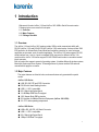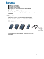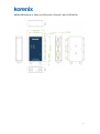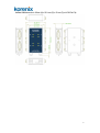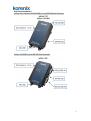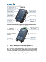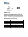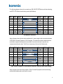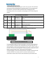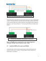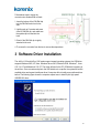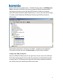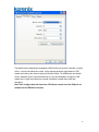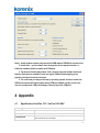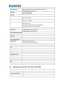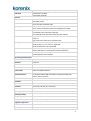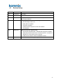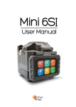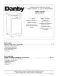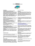
1
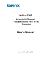
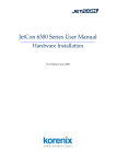
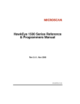
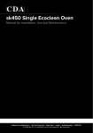
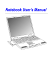
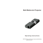
JetCon 1100 / 1200 USB to Serial Converter series User’s Manual Version 1.0 www.korenix.com 1 JetCon 1100 / JetCon 1200 User’s Manual Copyright Notice Copyright 2013 Korenix Technology Co., Ltd. All rights reserved. Reproduction in any form or by any means without permission is prohibited. 2 Declaration of CE This product has passed the CE certification for environmental specifications. Test conditions for passing included the equipment being operated within an industrial enclosure. In order to protect the product from being damaged by ESD (Electrostatic Discharge) and EMI leakage, we strongly recommend the use of CE-compliant industrial enclosure products. Federal Communications Commission (FCC) Statement This equipment has been tested and found to comply with the limits for a Class A digital device, pursuant to Part 15 of the FCC Rules. These limits are designed to provide reasonable protection against harmful interference when the equipment is operated in a commercial environment. This equipment generates, uses, and can radiate radio frequency energy and, if not installed and used in accordance with the instruction manual, may cause harmful interference to radio communications. Operation of this equipment in a residential area is likely to cause harmful interference in which case the user will be required to correct the interference at his expense. The user is cautioned that changes and modifications made to the equipment without approval of the manufacturer could void the user's authority to operate this equipment. 3 Index 1 2 3 4 Introduction.................................................................................................1 1.1 Overview ................................................................................................. 1 1.2 Major Features ......................................................................................... 1 1.3 Package List ............................................................................................ 2 Hardware Installation ....................................................................................3 2.1 Hardware Introduction ............................................................................... 3 2.2 Wiring to Serial Device (DCE) and Host Computer (DTE) ............................... 9 2.3 Install the USB /Serial Converter onto DIN Rail ........................................... 13 Software Driver Installation ..........................................................................14 Appendix ..................................................................................................17 4.1 Specification of JetCon 1101 / JetCon 1101i-5KV......................................... 17 4.2 4.3 4.4 4.5 4.6 Specification of JetCon 1102..................................................................... 18 Specification of JetCon 1104..................................................................... 19 Specification of JetCon 1201 /JetCon 1201i-3KV ......................................... 20 Revision History ...................................................................................... 23 About Korenix ......................................................................................... 24 1 Introduction Welcome to Korenix JetCon 1100 and JetCon 1200 USB to Serial Converter series. Following topics are covered in this chapter: 1.1 Overview 1.2 Major Features 1.3 Package Checklist 1.1 Overview The JetCon 1100 and JetCon 1200 series provides USB to serial communicate ability with RS-232 (JetCon 1100) and RS-422/ RS-485 (JetCon 1200) serial modes. It also provides 15KV ESD protection for Human Body Cotact Mode and Insulation protection for some extereme application environment, such as medical application. The JetCon 1100 series support RS-232 serial interface from 1 port to 4 ports in standard DB-9 connector for different JetCon 110x model; and the JetCon 1200 series support RS-422/ RS485 serial mode in removable terminal block connector. Both of product line supports several of operating system; it includes Microsoft windows system, Macintosh System and Linux System. To learning and use it, please read the QIG and user manual before apply the converter. 1.2 Major Features The major features are listed in below, and some features only presented for special model: JetCon 1100 Series USB / RS-232 DTE and DCE Connection RS-232 with Hand-Shaking function USB 1.1/1.2/2.0 compatible 921.6 Kbps High Speed Serial 12~480Mbps USB Data Throughput 15KV Human Body ESD protection 5KV Isolation for Medical Electrical Equipment (JetCon 1101i-5KV) -30~75°C wide operating temperature JetCon 1200 Series USB to RS_485 /RS_422 Serial Converter USB 1.1/1.2/2.0 compatible 921.6 Kbps High Speed Serial 12Mbps USB Data Throughput 1 Build-in 120ΩLine Terminator 32 x RS-485 devices connection 15KV Human Body ESD protection 3KV isolation, 600W Serial Port surge protection (JetCon 1201i-3KV) -30~75°C wide operating temperature The detail spec is listed in Session- 4 Appendix Note-1: those certifications are pending for special project request, please contact your sales widnow. 1.3 Package List Korenix JetCon 1100/ JetCon 1200 Series are shipped with following items: JetCon 1100 USB/ Serial RS-232 or JetCon 1200 USB/ Serial RS422/485 Converter One Mini-USB female to USB female cable Quick Installation Guide One CD-ROM with User manual and Drivers. JetCon 1101/1101i-5KV JetCon 1102 JetCon 1104 JetCon 1201/1201i-3KV USB to MINI USB Cable If any of the above items is missing or damaged, please contact your local sales representative. 2 2 Hardware Installation This chapter includes hardware introduction, installation and configuration information. Following topics are covered in this chapter: 2.1 Hardware Introduction Model Description Dimension Panel Layout 2.2 Wiring to Serial Device and Host Computer Connectting USB interface Connecting RS-232 (JetCon 1100 series) Connecting RS-422 / RS-485 (JetCon 1200 series) 2.1 Hardware Introduction This session will present different model with dimension and panel/bottom layout for the further install and configuration. Model Name and function description Model Name Product Description USB Port Serial Port ESD / Insulation Protect JetCon 1101 USB to 1-Port RS-232 Serial V1.1/ 1.2/ 2.0 12Mbps 1 x 921.6Kbps 15KV ESD JetCon 1101i-5kv USB to 1-Port RS-232 Serial V1.1/ 1.2/ 2.0 12Mbps 1 x 921.6Kbps 15KV ESD/ 5KV Isolation JetCon 1102 USB to 2-Port RS-232 Serial V1.1/ 1.2/ 2.0 480Mbps 2 x 921.6Kbps 15KV ESD JetCon 1104 USB to 4-Port RS-232 Serial V1.1/ 1.2/ 2.0 480Mbps 4 x 921.6Kbps 15KV ESD JetCon 1201 USB to 1-Port RS-422/485 Serial V1.1/ 1.2/ 2.0 12Mbps 1 x 921.6Kbps 15KV ESD JetCon 1201i-3kv USB to 1-Port RS-422/485 Serial V1.1/ 1.2/ 2.0 12Mbps 1 x 921.6Kbps 15KV ESD/ 3KV Isolation 3 JetCon 1101 / JetCon 1101i-5KV dimension is: 80 (H) x 42 (W) x 22 (D) / without DIN Rail Clip 4 JetCon 1102 dimension is: 89mm (H) x 58.3mm (W) x 22mm (D) / without DIN Rail Clip 5 JetCon 1104 dimension is: 89mm (H) x 62.6 mm (W) x 22 mm (D) w/o DIN Rail Clip 6 JetCon 1201 / JetCon 1201i-3KV dimension is: 89mm (H) x 62.6 mm (W) x 22 mm (D) w/o DIN Rail Clip 7 Deice Panel Introduction JetCon 1101 / JetCon 1101i-5KV USB to 1-port RS-232 Serial Converter JetCon 1102 USB to 2-port RS-232 Serial Converter 8 JetCon 1104 USB to 4-port Serial RS-232 Converter JetCon 1201 / JetCon 1201i-3KV USB to 1-port RS-422/RS-485 Serial Converter 2.2 Wiring to Serial Device (DCE) and Host Computer (DTE) The JetCon 1100 series and 1200 series support one Mini-USB interface with version 1.1/1.2 and 2.0, and the serial interface supports RS-232 for JetCon 1100 and RS-422/ RS-485 for JetCon 1200. The major function of JetCon 1100 and JetCon 1200 is provides logical serial interface for non-serial interface computer system which is only support USB port. Thus, it is not only connect the cabl, and also need install software driver to convert and make data link between logial serial com port and physical USB port. So, the first step is make connection between Conveter and Host computer – connecting USB interface. 9 Connecting USB Interface In the unit box, there is one Mini USB to USB cable, connects Converter and Host PC by this cable as following diagram. Connecting RS-232 Interface The RS-232 interface presented in JetCon 1100 series. In the session 2.1 Hardware Introduction have introduced the model name and function description. So, the JetCon 1100 series support RS-232 interface from 1 port to 4 ports, and JetCon 1101i-5KV provides isolated design for medical application, all of JetCon 1100 supports 15KV Human Body mode ESD protection. The RS-232 serial interface offer handshaking with fully communicatin control mechanism. Therefore, it could be connect to Data Communication Equipment, such as modem or other equipment without handshaking. The following table described the definitations of RS-232 signals with DB-9 and DB-25 connectors. DB-9 Pin No. DB-25 Pin No. Abbreviation Full Name 3 2 TD (TxD) Transmit Data 2 3 RD (RxD) Receive Data 7 4 RTS Request To Send 8 5 CTS Clear to Send 6 6 DSR Data Set Ready 5 7 S.G. Signal Ground 1 8 CD Carrier Detect 4 20 DTR Data Terminal Ready 9 22 RI Ring Indicator No mater the femal or male connector, the signal definitation of DB-9 and DB-25 follows the table above. 10 The following diagram shows the connections of RS-232 DTE-DTE device with hand-shaking, and DTE- DTE without hand-shaking mode (Null Modem). DB-9 DB-25 Signal Signal DB-25 DB-9 3 2 TD TD 2 3 2 3 RD RD 3 2 7 4 RTS RTS 4 7 8 5 CTS CTS 5 8 6 6 DSR DSR 6 6 5 7 S.G. S.G. 7 5 1 8 CD CD 8 1 4 20 DTR DTR 20 4 9 22 RI RI 22 9 Null Modem Connection Above diagram shows the best wiring method with 3 wires straight cable connection between 2 DTE (Data Terminal Computer / Host Computer). This method emulates modem behavior and makes computer thinking there is a modem is conneted, and each computer can communicate with each other. The RI is not necessary to link, just left it disconnect. DB-9 DB-25 Signal Signal DB-25 DB-9 3 2 TD TD 2 3 2 3 RD RD 3 2 7 4 RTS RTS 4 7 8 5 CTS CTS 5 8 6 6 DSR DSR 6 6 5 7 S.G. S.G. 7 5 1 8 CD CD 8 1 4 20 DTR DTR 20 4 9 22 RI RI 22 9 Data Terminal Computer vs Data terminal Computer connection with hand-shaking Above diagram shown the wiring between 2 Data Terminal Equipments with hand-shaking, and the hand-shaking also same as flow control. 11 Connecting RS-422/ RS-485 Interface The RS-422/ RS-485 interface only presented in JetCon 1201 and JetCon 1201i-3KV. Both of model support RS-422 and RS-485 serial communication ability in 5-pin removable terminal block connector. The RS-422/ RS485 communication does not support flow control / hand-shaking; therefore, the recommended connecting diagram and DIP-Switch setting show as below. JetCon 1200 Serial Mode Select DIP-Switch DIP-SW1 DIP-SW2 DIP-SW3 DIP-SW4 OFF OFF - ON OFF - OFF ON OFF OFF ON ON Serial Mode and Description ON ( with T.R. ) RS-422 4-Wire Serial Mode+ DIP-SW4 (120ohm line terminator resistor OFF (without T.R.) selection) ON ( with T.R. ) RS-485 4-Wire Serial Mode + DIP-SW4 (120ohm line terminator resistor OFF (without T.R.) selection) ON ( with T.R. ) RS-485 2-Wire Serial Mode without ECHO + DIP-SW4 (120ohm line OFF (without T.R.) terminator resistor selection) ON ( with T.R. ) RS-485 2-Wire Serial Mode with ECHO + DIP-SW4 (120ohm line terminator OFF (without T.R.) resistor selection) Note: Before mounting the JetCon1200 series, please setting the DIP-Switch first. RS-422 4-wire communication mode It is recommended to enable the 120 ohm line terminaltor, in case the connection distance is too short or signal is not stronger to offer a stable signale, then the wiring need install a 120 ohm line terminator onto the one node of the wire that cross TX+ and TX-, and RX+ and RX-. In the JetCon 1200 series, the system embedded 120ohm lne terminators and just click on the DI Switch to occupy the resistor on the 1st and last node of RS-422 serial bus. The following diagram is 4-wire RS-485 wiring architecture in full duplex communication mode. It is similar as RS-422 4-wire, and the network is connected so that the master node communicates to all slave nodes. All slave nodes communicate only with the master node. 12 RS-485 4-wire communication mode (Full Duplex Communication mode) The RS-485 multi-drop mode offers 32 nodes at same current loop bus, and it is recommended to enable 120ohm line terminator to obtain better data communication reliability in RS-485 bus. It is not necessary to add extra 120 ohm line terminator on each RS-485 node, just enable the DIP Switch-4 of line Terminator Resistor of 1st and last node of RS-485 bus for reliable current looping. RS-485 2-wire communication mode (Half Duplex Communication) Note: the RS-485 2-wire communication speed will downgrade to 57600bps if RS-485 2-wire link distance up to 1.2KM. 2.3 Install the USB /Serial Converter onto DIN Rail The DIN Rail clip is screwed on the rear panel of JetCon 1100 and JetCon 1200, which supports EN 50022 type rail installation. The below diagram includes the dimension of EN50022 rail for your reference. 13 Follow below steps to mount the converter onto standard DIN rail track. 1. Insert the bottom of the DIN-Rail clip into the DIN-Rail track from its low side. 2. Lightly push up Converter and press close to DIN-Rail clip, and make sure the upside clip is locked into the track. 3. Check if the DIN-Rail clip is tightly attached to the rack. 4. To remove the converter from the track, reverse the steps above. 3 Software Driver Installation The JetCon 1100 and JetCon 1200 series support several operating systems; the USB driver supports Windows 2000, XP, Vista, Windows Server 2003, Windows 2008, Windows 7, Linux O.S. 2.4~2.7 and Macintosh O.S. 6/7. The driver will exist in the CD_ROM which is packing in the unit box. Once connects and plus-in the USB interface to computer, the system will search available driver and request install new driver if computer did not install proper software driver before. The following figure shows the computer request user to install 4-port high speed USB/RS-232 driver. 14 Perform install driver from specific location – CD-ROM. The path of driver is CD-ROM\product \Driver\, and under the folder there are several sub-folders for different operating systems. Above figure shows there is 4-port High Speed RS-232 device. Therefore, the computer system will request install driver 4 times for physical port-1 to port-4, and in the device manager of computer system will add new USB-Serial port with new logical COM port number as following figure. If the computer system shows- “the driver is not verified..”, and asking to stop install driver. Then ingonre it and click the cutton “Continue Anyway” to finish the driver installation. Configure the COM port Properies Sleclec the USB/Serial COM port and click the right button of mouse, then into the USB serial Port Proerties setting interface. Click and select the parameters to matchserial baud rate with connection partner. The following picture show serial communication parameters includes bit rate, data bit, parity check mode,stop bit and flow control mode. 15 The default serial communication parameters is 9600 bit rate/ per second, 8 data bits, no parity check, 1 stop bit and without flow control. It also supports advanced configuration for USB transfer size, latency time, time out setting for Read and Write. The USB transfer size default value is maximum size for receive and transmit. It is not recommended to change the USB transfer size, it might cause data loss occurred if the buffer is smaller than serial data throughput. Note: don’t configure baud rate lower than 150 bits/per second, since the 150bps is not avaliabel for the USB/Serial converter. 16 Note:1. Install hadware system, and connect the USB cable to USB/Serial converter first. 2. Install drive – you can install driver through the device manger interface, or follow the hardware wizard to install each COM port. 3. The driver will install many times, if the converter supports multiple serial port function. Each dreiver installation creat one logical COM port and mapping to the physical serial port from first to last port. 4. The serial com port may not release by operating system, and once install new USB/serial conveter will cause system wrong COM port number occupy. In this case, user can configure the COM port setting to recovery the serial COM port. 4 Appendix 4.1 Specification of JetCon 1101 / JetCon 1101i-5KV Technology Standard EIA/TIA-232, RS-232 (ITU-T v.28) System performance Forwarding Rate USB 2.0 compatible with 12Mbps data throughput RS-232 baud rate up to 921.6Kbps 17 FIFO Buffer Transmit Buffer: 128Bytes Receive Buffer: 256Bytes Interface Connector Connection Distance Serial Parameters USB: Mini USB slave , B-Type Serial: DB-9, Female USB:5 Meters RS-232 Serial: 15 Meters Length of Data bit: 7, 8 bits Stop bit:1,2 Type of parity check: None, Even, Odd, Space, Mark Type of Flow Control: RTS/ CTS, XON/ XOFF Serial Signal TxD, RxD, RTS, CTS, DTR, DSR, DCD, GND System LED TX Blinking ( Green): Transmitting Data RX Blinking ( Amber): Receiving Data Operating System Support Windows XP, 2003, Vista, 2008, Win 7 Macintosh System 8, 9 Linux 2.4, 2.6 Power Requirements System Power Isolation System power Obtain from USB Host interface JetCon 1101 power consumption: 0.2W, 5V/40mA (Max) JetCon 1101i-5KV power consumption:0.27W, 5V/55mA (Max) 5KV insulation between USB Host interface and RS-232 interface (JetCon 1101i-5KV) Mechanical Installation DIN Rail mount Case Plastic Case with IP-30 protection Dimension 93.3 mm (H) x 42 mm (W) x 22 mm (D) Weight JetCon 1101: 0.22kg with package JetCon 1101i-5KV: 0.225kg with package Environmental Operating Temperature -30°C ~75°C Operating Humidity 0% ~ 90% non-condensing Storage Temperature -40°C ~ 80°C Storage Humidity 0%~ 95%, non-condensing Regulatory Approvals EMC CE, FCC Class A Warranty 3 Years 4.2 Specification of JetCon 1102 Technology Standard EIA/TIA-232, RS-232 (ITU-T v.28) 18 System performance Forwarding Rate FIFO Buffer USB 2.0 compatible with maximum 480Mbps data throughput RS-232 baud rate up to 921.6Kbps Transmit Buffer: 4KBytes Receive Buffer: 4KBytes Interface Connector Connection Distance Serial Parameters USB: Mini USB slave , B-Type Serial: 2 x DB-9- Male USB:5 Meters RS-232 Serial: 15 Meters Length of Data bit: 7, 8 bits Stop bit:1,2 Type of parity check: None, Even, Odd, Space, Mark Type of Flow Control: RTS/ CTS, XON/ XOFF Serial Signal TxD, RxD, RTS, CTS, DTR, DSR, DCD, GND System LED TX Blinking ( Green): Transmitting Data RX Blinking (Amber): Receiving Data Operating System Support Windows XP, 2003, Vista, 2008, Win 7 Macintosh System 8, 9 Linux 2.4, 2.6 Power Requirements System Power Obtain from USB Host interface Power consumption: 0.57W, 5V/ 115mA (Max.) Mechanical Installation DIN Rail mount Case Plastic Case with IP-30 protection Dimension 89mm(H) x 58.3mm (W) x 22mm (D) Weight 0.235kg with package Environmental Operating Temperature -30°C ~75°C Operating Humidity 0% ~ 90% non-condensing Storage Temperature -40°C ~ 80°C Storage Humidity 0%~ 95%, non-condensing Regulatory Approvals EMC CE, FCC A Warranty 3 years 4.3 Specification of JetCon 1104 Technology Standard EIA/TIA-232, RS-232 (ITU-T v.28) 19 System performance Forwarding Rate FIFO Buffer USB 2.0 compatible with maximum 480Mbps data throughput RS-232 baud rate up to 921.6Kbps Transmit Buffer: 2KBytes Receive Buffer: 2KBytes Interface Connector Connection Distance Serial Parameters USB: Mini USB slave , B-Type Serial: 4 x DB-9- Male USB:5 Meters RS-232 Serial: 15 Meters Length of Data bit: 7, 8 Bits Stop Bit:1Bit, 2 Bits Type of parity check: None, Even, Odd, Space, Mark Type of Flow Control: RTS/ CTS, XON/ XOFF Serial Signal TxD, RxD, RTS, CTS, DTR, DSR, DCD, GND System LED TX Blinking (Green): Transmitting Data RX Blinking (Amber): Receiving Data Operating System Support Windows XP, 2003, Vista, 2008, Win 7 Macintosh System 8, 9 Linux 2.4, 2.6 Power Requirements System Power Obtain from USB Host interface Power Consumption: 0.83W, 5V/0.165A Mechanical Installation DIN Rail mount Case Plastic Case with IP-30 protection Dimension 89mm(H) x 62.6 mm (W) x 22 mm (D) w/o DIN Rail Clip Environmental Operating Temperature -30°C ~75°C Operating Humidity 0% ~ 90% Non-Condensing Storage Temperature -40°C ~ 80°C Storage Humidity 0%~ 95%, Non-Condensing Regulatory Approvals EMC CE, FCC Class A Warranty 3 Years 4.4 Specification of JetCon 1201 /JetCon 1201i-3KV Technology Standard TIA/EIA RS-422, TIA/EIA RS-485 System performance Forwarding Rate USB 2.0 compatible with maximum 12Mbps data throughput 20 FIFO Buffer RS-422 / RS-485 baud rate up to 921.6Kbps Transmit Buffer: 128 Bytes Receive Buffer: 256 Bytes Interface Connector USB: Mini USB slave , B-Type Serial: DB-9, Female Cable for Serial Interface RS-422 / RS-485: Twisted Pair Cable. Operating Mode Select and Control by DIP Switch setting. Build-in 120ohm line terminator resistor and configured by DIP Switch. USB:5 Meters 4-wire RS-422 mode: 1500 meters (4,900 feet) 2/4-wire RS-485 mode: 1200 meters (4,000 feet), Max 32 Nodes. Length of Data bit: 7, 8 bits Stop bit:1,2 Type of parity check: None, Even, Odd, Space, Mark RS-422: TX+, TX-, RX+, RX-, Signal GND. RS-485 (4-Wire): TX+, TX-, RX+, RX-, Signal GND RS-485 (2-Wire):Data+, Data-, Signal GND Serial communication mode selection (DIP-Switch 1,2),RS_485 ECHO mode selection (DIP-Switch 3), Line Terminator selection (DIP-Switch 4) TX Blinking ( Green): Transmitting Data RX Blinking (Amber): Receiving Data Connection Distance Serial Parameters Serial Signal DIP Switch System LED Operating System Support Windows XP, 2003, Vista, 2008, Win 7 Macintosh System 8, 9 Linux 2.4, 2.6 Power Requirements System Power Obtain from USB Host interface Isolation Protection 3KV insulation between USB Host interface and RS-422/ RS-485 serial interface (JetCon 1201i-3KV) Mechanical Installation DIN Rail mount Case Plastic Case with IP-30 protection Dimension 101.9 mm(H) x 42.0mm (W) x 22.0mm (D) Environmental Operating Temperature -30°C ~75°C Operating Humidity 0% ~ 90% non-condensing Storage Temperature -40°C ~ 80°C Storage Humidity 0%~ 95%, non-condensing Regulatory Approvals EMC CE, FCC A Warranty 3 Years 21 22 4.5 Revision History Edition Date Modifications V01 25-Feb-2013 New editting V02 27-Feb,2013 Update with driver path. V03 12-Mar-2013 Modify RS-485 four-wire architecture and add some description for RS-485 and RS-422 wiring architecture. V04 15-Mar-2013 Update product specification with I-Testing’s suggestion: 1. RX LED change to amber color 2. Modify USB 2.0 compatible.. 3. Add power consumption 4. Update advanced configuration for buffer and installation. 5. Add installation. V05 29-Mar-2013 Update information after Integration testing 1. Add note about the 485 baudrate: 1.2KM, Baudrate downgrade to 57600bps 2. Modify RS_485 line terminate resistor: add line terminator at 1st and last not of RS-485 bus, if communication quality is not stable. 3. COM port will not release if install more USB/Serial converter. V1.0 Apr-2013 1. Final version, remove front page wrong information. 23 4.6 About Korenix Less Time At Work! Fewer Budget on applications! The Korenix business idea is to let you spend less time at work and fewer budget on your applications. Do you really want to go through all the troubles but still end up with low quality products and lousy services? Definitely not! This is why you need Korenix. Korenix offers complete product selection that fulfills all your needs for applications. We provide easier, faster, tailor-made services, and more reliable solutions. In Korenix, there is no need to compromise. Korenix takes care of everything for you! Fusion of Outstandings You can end your searching here. Korenix Technology is your one-stop supply center for industrial communications and networking products. Korenix Technology is established by a group of professionals with more than 10 year experience in the arenas of industrial control, data communications and industrial networking applications. Korenix Technology is well-positioned to fulfill your needs and demands by providing a great variety of tailor-made products and services. Korenix’s industrial-grade products also come with quality services. No more searching, and no more worries. Korenix Technology stands by you all the way through. Core Strength---Competitive Price and Quality With our work experience and in-depth know-how of industrial communications and networking, Korenix Technology is able to combine Asia’s research / development ability with competitive production cost and with quality service and support. Global Sales Strategy Korenix’s global sales strategy focuses on establishing and developing trustworthy relationships with value added distributors and channel partners, and assisting OEM distributors to promote their own brands. Korenix supplies products to match local market requirements of design, quality, sales, marketing and customer services, allowing Korenix and distributors to create and enjoy profits together. Quality Services KoreCARE--- KoreCARE is Korenix Technology’s global service center, where our professional staffs are ready to solve your problems at any time and in real-time. All of Korenix’s products have passed ISO-9000/EMI/CE/FCC/UL certifications, fully satisfying your demands for product quality under critical industrial environments. Korenix global service center’s e-mail is [email protected] Business service : [email protected] Customer service: [email protected] 24