1
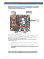
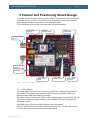
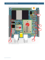
Cellular and Positioning Shield - User’s Guide Page 9 Next, connect the shield to a system. It can be via the Arduino, Raspberry Pi connectors or, in the case of the 3G version, a direct USB connection to a PC. As an illustrated example, the picture below shows the shield mounted on the LPC4088 Experiment Bundle. micro-B USB connector for powering Cellular and Positioning shield GPS/GNSS antenna connector Cellular antenna connector Figure 2 –Shield Mounted on LPC4088 Experiment Bundle The next step is to mount the antennas. Only use the antennas that are shipped with the shield. The picture above also shows where the GPS/GNSS and cellular antennas shall be mounted. The GPS/GNSS antenna has a big puck/box at the very end and a long antenna cable. The cellular antenna is short and connects directly to the SMA connector. The final step is to provide an external power source to the shield. A 5-12V DC / 1Amp supply is suitable. Three options exist: 4.2 Power the shield via the micro-B USB connector. This will by default be a 5V supply, for example a USB charger. Power the shield via the Arduino connectors; either the +5V power supply or the VIN (12V max) power supply can power the shield, whichever has highest voltage. Power the shield via the Raspberry Pi connector; pin 2, 4 are +5V input and pin 6, 9, 14, 20, 25 are ground. m-center Application u-box has created a (Windows) PC application for direct evaluation, configuration and testing of the cellular modem. The application is called m-center. The PC application communicates with the cellular modem via the UART channel. The application can be downloaded from here: http://www.u- Copyright 2014 © Embedded Artists AB