1
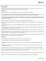
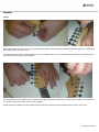
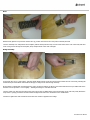
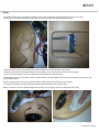
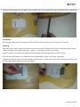
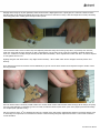
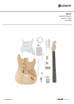
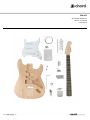
CAL-K1
SELF-BUILD GUITAR KIT
Item ref: 174.460UK
User Manual
Introduction
Thank you for buying the CAL-K1 kit. All the wood, hardware and electrical components of a Chord CAL93 guitar are contained in this
package. Please read the following instructions to help with assembly and finishing
Body Finish
The first consideration to be made before assembly is choosing the preferred finish of the guitar body.
The alder body of the CAL-K1 is sealed and prepared for various types of lacquer coating. A wide variety of finishes can be procured from
DIY, timber and automotive outlets in aerosol cans making finishing straightforward without requiring specialist skills.
Firstly, check the fit of the body to neck joint. The CAL-K1 is machined from very high grade tone-woods to avoid any misalignments but
all woods have a natural propensity to change shape very slightly over time. If the fit is too tight, gentle adjustment using a sharp chisel
or sandpaper may be required.
Please remember that the coating of lacquer will make the neck fit a little more tightly into the pocket.
Before coating the body, ensure all surfaces are clean and free of dirt and dust. Conduct all coating processes in a well-aired, dust-free
environment.
Slow and patient progress is the key to a good quality body finish and it is advised to test the colour and technique on a spare piece of
wood first.
A hole is drilled in the neck pocket so that it can be suspended by a hook for spraying and drying or alternatively, a spare length of wood
can be screwed in place of the neck in the pocket as a handle.
Spray the edges of the body first and allow to “touch-dry”. Once the edges are dry, move on to the back and then the front of the body.
Gradual and smooth passes will ensure an even coat. If there are any imperfections, allow to fully dry and then sand out with fine grade
(e.g. 800+ grit) before re-spraying. Apply 3 or more coats for full coverage.
Finally, after allowing 2 to 3 days drying to fully cure the finish, then buff or polish the body as required to give the desired level of gloss.
Take care not to buff too vigorously as this may remove the finish.
Neck finish
The neck of the CAL-K1 is supplied sealed with a light coat of matte lacquer and is ready to use.
If preferred, the neck can be finished with a colour or gloss lacquer. If so, do the following.
The rosewood fingerboard does not need coating with lacquer, so it is important to mask off the exposed rosewood and frets prior to
spraying.
Ensure all parts to be sprayed are free from dirt and dust and that the environment is dust-free and well-aired. Use of a dust-mask is
essential when spraying.
Choose a good quality, clear or lightly tinted wood lacquer aerosol for the neck and begin with the front and sides of the headstock.
Start with a gradual, even pass to apply a thin coat, allow drying (to the touch) and repeating 2 or 3 times, taking care not to apply too
much, which may cause runs. If this happens, sand down the area and re-apply evenly.
When the headstock is dry, turn the neck over and lay it on its fingerboard. Repeat the above process for the rest of the exposed maple.
Allow 2 to 3 days for the lacquer to fully harden and then, if desired, polish the lacquered surfaces to a suitable shine.
174.460UK User Manual
Assembly
Tuners
Before attaching the neck to the body, fit the tuning machine-heads to the headstock by inserting the thread through the pre-drilled holes
and setting a washer and bush over it.
Screw down the bush onto the thread until tight to the touch and then adjust the rear of the machine-head so that the tuning button sits
vertically above the top edge of the headstock
Fix the retaining screw through the loop on the rear of the gear housing into the pilot hole to hold the tuner in position. Then tighten the
nut on the front face of the tuner until firm using a spanner
Repeat this for the remaining 5 tuners and then fit the 2 string trees with the one with the taller spacers nearer to the top nut.
174.460UK User Manual
Neck
With the body placed on a protective surface face-up, position the neck into the neck pocket until fully inserted.
Turn the assembly over and position the neck plate (with its black protective seal) over the 4 bolt-holes at the rear of the body and drive
in the 4 long screws through the neck plate, body and pilot holes in the neck until tight.
Bridge assembly
Lie the body face-up on a soft surface. Take the vibrato bridge and sit it into the routed section toward the rear of the body, allowing the
sustain block (the metal block underneath the bridge) to hang into the hole through the body.
Ensure that the sustain block is positioned in the centre of the hole and line up the six screw holes that have been pre-drilled and secure
with the 6 screws provided – not too tightly – allowing the bridge to rock back and forth.
Turn the guitar over and screw the spring claw part-way into the pre-drilled holes at the forward edge of the rear body cavity Attach the
loops of the 3 springs provided to the claw and the straight hook ends to the small holes in the sustain block.
Continue to tighten the claw towards the neck until some tension is applied to the bridge.
174.460UK User Manual
Wiring
The Ground or Earth wire is a loose wire soldered to a pot on the scratch plate assembly (below you can see it in yellow)
This Ground wire should be threaded through the body via the hole inside the cavity as shown below left.
Turning the guitar body over, the Ground wire should be visible in the rear body cavity (above right)
The tinned end of this wire should be inserted into the small flap on the vibrato claw as shown in the photograph
To ensure a good connection, squeeze the flap down onto the Earth wire with some pliers.
Turning again to the front of the guitar, feed the signal connector (on the red/black wires from the scratch plate) through to the jack
cavity as shown below.
Push the signal connector from the scratch plate and the signal connector from the jack socket together.
Screw the jack socket into the jack cavity and carefully fit the scratch plate over the main cavity.
Making sure that no wires are trapped and that it fits properly over the cavity, screw the scratch plate to the body.
174.460UK User Manual
The plastic rear body plate can now be fitted to cover the spring cavity. Secure the plate with dome-head screws into the pre-drilled holes.
Strap buttons
Screw the strap buttons into the pre-drilled holes at the rear edge of the body and at the tip of the upper horn of the body.
Setting up
Fitting strings to the guitar is achieved by threading from the rear, through the sustain block to the front, emerging through the relevant
saddle on the bridge. Start with the thickest string – bottom E – in the uppermost position on the bridge.
Stretch the strings in turn, keeping them straight across the fretboard and into the appropriate groove in the top nut.
Ensure the string sits smoothly over its saddle and keep taut whilst winding a couple of turns on the relevant tuner.
Thread through the string post and bend the string back on itself to anchor it in place. Apply a little tension from the tuner and move on to
the next string, repeating the above process for all 6 strings.
174.460UK User Manual
Bringing all the strings up to pitch gradually is better achieved with a digital guitar tuner or pitch pipes as a reference. Please be aware
that the tension in the strings and vibrato springs may take some time to settle and re-tuning a few times might be necessary. Stretching
each string gently after reaching pitch will help to take up slack.
The neck is fitted with a truss rod which may need adjusting. When the strings are tuned up, they will try to pull away from the neck,
which may mean that the action becomes too high. If this happens, use the larger of the 2 hex keys provided to gradually tighten the
truss rod – a half turn is usually enough and may not take effect immediately – allow adjustments to settle each time – do not be tempted
to over-tighten the truss rod.
Sighting along the neck should show a very slight concave tendency – this is called “relief” and too straight a neck may lead to “fret
buzzing”.
Some strings may need to be raised or lowered individually to give the correct action and this can be adjusted using the smaller of the 2
hex keys provided.
Once the desired action is achieved, all that remains is to set the vibrato tension and intonation. After tuning up all the strings, the spring
claw may need tightening (or slackening) in the rear cavity to make the vibrato system “float” (note: some players prefer that the bridge
lies completely flat against the body).
Also, the harmonic at the 12th fret should be the same as a fretted note in this position. Adjusting the saddle for each string back or forth
on the bridge can compensate for inconsistencies with this. Careful listening and gentle adjustment until the 2 notes match will achieve
correct intonation.
174.460UK User Manual
Please also remember that over time, slight adjustments may need to be made and different gauges of strings will need compensating for
in the set up.
Pickup height can now be adjusted for best performance and balance by adjusting the screws at top and bottom of each pickup. As a
general rule, hold down the strings at the 22nd fret and adjust so that the strings are at least 2mm clear of the pickup. Any pickups that
are noticeably louder than others can be made quieter by adjusting them further away from the strings.
For future adjustments, keep these instructions as a reference and enjoy your custom made Chord CAL guitar.
Errors and omissions excepted.
Copyright© 2014. AVSL Group Ltd.
174.460UK User Manual