1
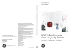
ÄKTA™ ready
Operating Instructions
Original instructions
Table of Contents
Table of Contents
1
Introduction ..........................................................................................................
1.1
1.2
1.3
2
3
4
5
6
7
7
9
12
Safety instructions ...............................................................................................
14
2.1
2.2
2.3
2.4
2.5
Safety precautions ...............................................................................................................................
Labels .........................................................................................................................................................
Emergency procedures ......................................................................................................................
Recycling information .........................................................................................................................
Declaration of Hazardous Substances (DoHS) ........................................................................
15
24
27
30
31
System description ..............................................................................................
33
3.1
3.2
3.3
3.4
3.5
Overview ...................................................................................................................................................
Layout ........................................................................................................................................................
Flow chart ................................................................................................................................................
Equipment ................................................................................................................................................
UNICORN control system ..................................................................................................................
34
36
45
48
52
Installation ............................................................................................................
55
4.1
4.2
4.3
4.4
4.5
4.6
Included in the delivery ......................................................................................................................
Site requirements ..................................................................................................................................
Transport ..................................................................................................................................................
Unpacking ................................................................................................................................................
Positioning the system .......................................................................................................................
Connections ............................................................................................................................................
57
58
60
65
66
67
Starting ÄKTA ready .............................................................................................
74
5.1
5.2
Start and log on to UNICORN ..........................................................................................................
Start the system ....................................................................................................................................
75
76
Flow kit installation .............................................................................................
77
6.1
6.2
6.3
ÄKTA ready flow kits ............................................................................................................................
Unpacking the flow kit ........................................................................................................................
Mounting the flow kit ..........................................................................................................................
78
80
81
ÄKTA ready gradient ............................................................................................
97
7.1
7.2
7.3
8
2
5
Important user information .............................................................................................................
Regulatory information ......................................................................................................................
Associated documentation ..............................................................................................................
ÄKTA ready gradient pump ..............................................................................................................
ÄKTA ready gradient flow section .................................................................................................
Calibrate and operate the ÄKTA ready gradient pump ......................................................
98
99
103
Component test ....................................................................................................
107
8.1
108
Run a component test ........................................................................................................................
ÄKTA ready Operating Instructions 28960345 AD
Table of Contents
8.2
8.3
The test report ........................................................................................................................................
Troubleshooting a failed component test .................................................................................
113
117
Column installation .............................................................................................
122
9.1
9.2
9.3
9.4
9.5
Columns ....................................................................................................................................................
Installing a column ...............................................................................................................................
Optional column test ...........................................................................................................................
Optional column rinsing ....................................................................................................................
Adding columns to the column list ...............................................................................................
124
127
135
138
139
10 Creating a method ...............................................................................................
141
9
10.1
The Method Editor ................................................................................................................................
10.1.1
10.1.2
10.1.3
10.2
143
145
147
An example of using the Method Editor .....................................................................................
152
10.2.1
10.2.2
10.2.3
10.2.4
10.2.5
10.2.6
10.2.7
10.2.8
10.2.9
10.2.10
10.2.11
10.3
142
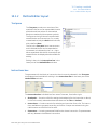
Introduction to the Method Editor ..........................................................................................
Method Editor layout ....................................................................................................................
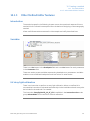
Other Method Editor features ...................................................................................................
Creating the method and selecting a column ...................................................................
Block 1: Opening valves ..............................................................................................................
Block 2: Auto-zeroing pressure sensors ...............................................................................
Block 3: Setting PID parameters ..............................................................................................
Block 4: Filling the flow kit ..........................................................................................................
Block 5: Equilibration ....................................................................................................................
Block 6: Sample load ....................................................................................................................
Block 7: Washing unbound sample .......................................................................................
Block 8: Elution ................................................................................................................................
Block 9: Regeneration ..................................................................................................................
Saving the method ........................................................................................................................
153
154
156
157
158
160
161
163
164
166
167
Creating a column efficiency test .................................................................................................
168
11 Run a method ........................................................................................................ 170
11.1
11.2
11.3
11.4
Final preparations before a run .....................................................................................................
Starting a run ..........................................................................................................................................
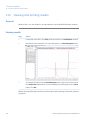
Viewing and printing results ............................................................................................................
After the run ............................................................................................................................................
171
175
178
180
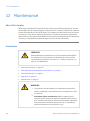
12 Maintenance .........................................................................................................
182
12.1
12.2
12.3
12.4
Daily maintenance ...............................................................................................................................
Yearly maintenance .............................................................................................................................
Spare parts ..............................................................................................................................................
Storage ......................................................................................................................................................
184
187
194
195
13 Troubleshooting ...................................................................................................
196
14 Reference information ........................................................................................
201
14.1
14.2
14.3
14.4
Specifications .........................................................................................................................................
Process wetted materials .................................................................................................................
Chemical resistance ............................................................................................................................
Ordering information ..........................................................................................................................
ÄKTA ready Operating Instructions 28960345 AD
202
206
207
210
3
Table of Contents
14.5
14.6
14.7
14.8
4
PID control ................................................................................................................................................
Checklists ..................................................................................................................................................
Health and Safety Declaration Form ...........................................................................................
More information ..................................................................................................................................
214
216
221
223
Index .......................................................................................................................
224
ÄKTA ready Operating Instructions 28960345 AD
1 Introduction
1
Introduction
Purpose of the Operating
Instructions
The Operating Instructions provides you with the instructions needed to handle ÄKTA ready
in a safe way.
It also describes the procedures required to operate ÄKTA ready on a day-to-day basis,
as well as technical information and instructions for troubleshooting and maintenance.
Prerequisites
In order to operate the system in the way it is intended, the following pre-requisites must
be fulfilled:
•
You should have a general understanding of how a PC and Microsoft® Windows®
works.
•
The user must have a working knowledge of UNICORN™ software. A user account
has been created according to the UNICORN™ Administration and Technical Manual.
•
The user must be acquainted with the use of general bioprocessing equipment and
with handling of biological materials.
•
The user must read and understand Chapter 2 Safety instructions, on page 14.
About this chapter
This chapter contains important user information, regulatory information, list of associated documentation, definitions of safety notices, etc.
ÄKTA ready Operating Instructions 28960345 AD
5
1 Introduction
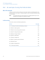
In this chapter
This chapter contains the following sections:
Section
1.1 Important user information
7
1.2 Regulatory information
9
1.3 Associated documentation
6
See page
12
ÄKTA ready Operating Instructions 28960345 AD
1 Introduction
1.1 Important user information
1.1
Important user information
Read this before using
ÄKTA ready
All users must read the safety instructions in the ÄKTA ready user documentation to
fully understand the safe use of ÄKTA ready, before installing, using, or maintaining the
system.
Do not operate the ÄKTA ready system in any other way than described in the user
documentation. Otherwise, you may be exposed to hazards that can lead to personal
injury, and you may cause damage to the equipment.
Safety notices
This user documentation contains WARNINGS, CAUTIONS and NOTICES concerning the
safe use of the product. See definitions below.
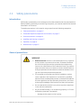
Warnings
WARNING
WARNING indicates a hazardous situation which, if not avoided,
could result in death or serious injury. It is important not to proceed
until all stated conditions are met and clearly understood.
Cautions
CAUTION
CAUTION indicates a hazardous situation which, if not avoided,
could result in minor or moderate injury. It is important not to
proceed until all stated conditions are met and clearly understood.
ÄKTA ready Operating Instructions 28960345 AD
7
1 Introduction
1.1 Important user information
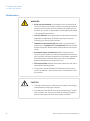
Notices
NOTICE
NOTICE indicates instructions that must be followed to avoid
damage to the product or other equipment.
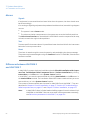
Notes and tips
Note:
A note is used to indicate information that is important for trouble-free and
optimal use of the product.
Tip:
A tip contains useful information that can improve or optimize your procedures.
Typographical conventions
Software items are identified in the text by bold italic text. A colon separates items in a
group, for example Flowpath:Injection valve refers to the Injection valve item in the
Flowpath group.
Hardware items are identified in the text by bold text (for example, the Power button).
8
ÄKTA ready Operating Instructions 28960345 AD
1 Introduction
1.2 Regulatory information
1.2
Regulatory information
In this section
This section describes the directives and standards that are fulfilled by ÄKTA ready.
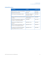
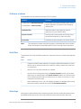
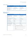
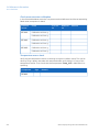
Manufacturing information
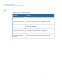
The table below summarizes the required manufacturing information. For further information, see the EU Declaration of Conformity (DoC) document.
Requirement
Content
Name and address of manufacturer
GE Healthcare Bio-Sciences AB,
Björkgatan 30, SE 751 84 Uppsala, Sweden
Conformity with EU Directives
This product complies with the European directives listed in the table, by fulfilling the
corresponding harmonized standards.
A copy of the EU Declaration of Conformity is included in the documentation package.
Directive
Title
2011/65/EU
Restriction of Hazardous Substances (RoHS) Directive
2006/42/EC
Machinery Directive (MD)
2004/108/EC
Electromagnetic Compatibility (EMC) Directive
2006/95/EC
Low Voltage Directive (LVD)
ÄKTA ready Operating Instructions 28960345 AD
9
1 Introduction
1.2 Regulatory information
CE marking
The CE marking and the corresponding EU Declaration of Conformity is valid for the instrument when it is:
•
used as a stand-alone unit, or
•
connected to other products recommended or described in the user documentation,
and
•
used in the same state as it was delivered from GE Healthcare, except for alterations
described in the user documentation.
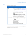
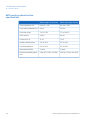
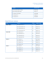
International standards
Harmonized standard requirements fulfilled by this product are summarized in the following table:
Standard
Description
Notes
EN ISO 12100
Safety of machinery. General
principles for design. Risk assessment and risk reduction.
EN ISO standard is harmonized with EU directive 2006/42/EC
EN/IEC 61010-1,
UL61010-1, CAN/CSA
C22.2 No. 61010-1
Safety requirements for electrical equipment for measurement, control, and laboratory
use.
EN standard is harmonized with EU directive
2006/95/EC
EN/IEC 61326-1
Electrical equipment for measurement, control and laboratory use - EMC requirements
EN standard is harmonized with EU directive
2004/108/EC
(Emission according
to CISPR 11, Group 1,
class A)
10
ÄKTA ready Operating Instructions 28960345 AD
1 Introduction
1.2 Regulatory information
FCC compliance
This device complies with part 15 of the FCC Rules. Operation is subject to the following
two conditions: (1) This device may not cause harmful interference, and (2) this device
must accept any interference received, including interference that may cause undesired
operation.
Note:
The user is cautioned that any changes or modifications not expressly approved
by GE Healthcare could void the user’s authority to operate the equipment.
This equipment has been tested and found to comply with the limits for a Class A digital
device, pursuant to part 15 of the FCC Rules. These limits are designed to provide reasonable protection against harmful interference when the equipment is operated in a
commercial environment. This equipment generates, uses, and can radiate radio frequency energy and, if not installed and used in accordance with the instruction manual, may
cause harmful interference to radio communications. Operation of this equipment in a
residential area is likely to cause harmful interference in which case the user will be required to correct the interference at his own expense.
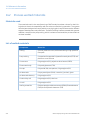
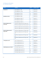
Environmental conformity
This product conforms to the following environmental requirements.
Requirement
Title
2012/19/EU
Waste Electrical and Electronic Equipment (WEEE) Directive
94/62/EC and
2004/12/EC
Packaging and Packaging Waste Directive and amendment
ACPEIP
Administration on the Control of Pollution Caused by Electronic
Information Products, China Restriction of Hazardous Substances (RoHS)
Regulation (EC)
No 1907/2006
Registration, Evaluation, Authorization and restriction of
CHemicals (REACH)
Regulatory compliance of
connected equipment
Any electrical equipment connected to ÄKTA ready should meet the safety requirements
of EN/IEC 61010-1, or relevant harmonized standards. Within EU, connected equipment
must be CE marked.
ÄKTA ready Operating Instructions 28960345 AD
11
1 Introduction
1.3 Associated documentation
1.3
Associated documentation
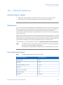
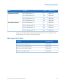
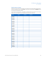
Generic documentation
Together with each system, the following manuals are supplied providing information
that applies to ÄKTA ready independent of the specific configuration.
1
Document
Purpose/Contents
ÄKTA ready Operating
Instructions
Instructions on how to handle ÄKTA ready in a safe
way (this manual).
UNICORN™ User Manual
package 1
Detailed instructions on how to use the UNICORN
control system.
ÄKTA ready can be controlled by both UNICORN 5 and UNICORN 7.
Third-party component
documentation
Documentation for components produced by a third-party are, if existent, also included
in the document package.
12
ÄKTA ready Operating Instructions 28960345 AD
1 Introduction
1.3 Associated documentation
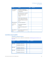
Related literature
Document
Product
Product code
ReadyToProcess™ columns User Manual
User Manual
28925644
ReadyToProcess columns
Data file
28915987
ÄKTA ready chromatography system
Data file, including Site
Preparation Guide
28915986
Keep your ÄKTA ready operating in peak
condition
Preventive Maintenance
PM Fact Sheet
28998083
Process chromatography: A guide to optimization, scale-up and validation
Handbook
18112156
Efficiency test of ReadyToProcess
columns
Application note
28919821
Ready-to-use fluid management solutions for chromatography systems
Application note
28995879
Purification of a monoclonal antibody
using ReadyToProcess™ columns
Application note
28919856
ÄKTA ready Operating Instructions 28960345 AD
13
2 Safety instructions
2
Safety instructions
About this chapter
This chapter describes safety precautions and emergency shutdown procedures for the
product. The labels on the system and information regarding recycling are also described.
Important
WARNING
Before installing, operating or maintaining the product, all users
must read and understand the entire contents of this chapter
to become aware of the hazards involved.
In this chapter
This chapter contains the following sections:
Section
14
See page
2.1 Safety precautions
15
2.2 Labels
24
2.3 Emergency procedures
27
2.4 Recycling information
30
2.5 Declaration of Hazardous Substances (DoHS)
31
ÄKTA ready Operating Instructions 28960345 AD
2 Safety instructions
2.1 Safety precautions
2.1
Safety precautions
Introduction
ÄKTA ready is powered by mains voltage and handles materials that may be hazardous.
Before installing, operating or maintaining the system, you must be aware of the hazards
described in this manual.
The safety precautions in this section are grouped into the following categories:
•
General precautions, on page 15
•
Flammable liquids and explosive environment, on page 17
•
Personal protection, on page 16
•
Installing and moving, on page 17
•
Operation, on page 19
•
Maintenance, on page 22
General precautions
WARNING
•
Risk assessment. Perform a risk assessment for any risks due
to the process or process environment. Evaluate the effects
the use of the product and the operational processes may
have on the classification of the hazardous area. The process
might cause the area to increase or the zone classification to
change. Implement the risk reduction measures needed, including use of personal protective equipment.
•
The customer must make sure that all installation, maintenance, operation and inspection is carried out by qualified
personnel who are adequately trained, understand and adhere
to local regulations and the operating instructions, and have
a thorough knowledge of the product and the entire process.
•
Do not operate the product in any other way than described
in the user documentation.
•
Do not use ÄKTA ready if it is not working properly, or if it has
suffered any damage, for example:
-
ÄKTA ready Operating Instructions 28960345 AD
damage to the power cord or its plug
15
2 Safety instructions
2.1 Safety precautions
WARNING
-
damage caused by dropping the equipment
-
damage caused by splashing liquid onto it
•
Emergency stop. Pressing the EMERGENCY STOP does not
automatically depressurize the flow path.
•
Do not use any accessories not supplied or recommended by
GE Healthcare.
CAUTION
•
Waste tubes and containers must be secured and sealed to
prevent accidental spillage.
•
Make sure that the waste container is dimensioned for maximum possible volume when the equipment is left unattended.
NOTICE
Any computer used with the equipment must comply with IEC
60950 and be installed and used according to the manufacturer's
instructions.
Personal protection
WARNING
16
•
Always use appropriate Personal Protective Equipment (PPE)
during operation and maintenance of this product.
•
Hazardous substances and biological agents. When using
hazardous chemical and biological agents, take all suitable
protective measures, such as wearing protective glasses and
gloves resistant to the substances used. Follow local and/or
national regulations for safe operation and maintenance of
ÄKTA ready.
ÄKTA ready Operating Instructions 28960345 AD
2 Safety instructions
2.1 Safety precautions
WARNING
•
Personal Protective Equipment (PPE). Whenever packing,
unpacking, transporting or moving the product, wear:
-
Protective footwear, preferably with steel toe-cap.
-
Working gloves, protecting against sharp edges.
-
Protective glasses.
Flammable liquids and explosive
environment
WARNING
•
Flammable liquids. This product is not approved to handle
flammable liquids.
•
Explosive environment. The product is not approved for work
in a potentially explosive atmosphere, in areas classified as
Zone 0 to Zone 2 according to IEC 60079-10 2002. The product
does not fulfill the requirements of the ATEX Directive.
Installing and moving
WARNING
•
Move transport crates. Make sure that the lifting equipment
has the capacity to safely lift the crate weight. Make sure that
the crate is properly balanced so that it will not accidentally
tip when moved.
•
Heavy object. Because of the significant weight of the product,
great care must be taken not to cause squeezing or crushing
injuries during movement. At least two, but preferably three
or more, people are recommended when moving the unit.
ÄKTA ready Operating Instructions 28960345 AD
17
2 Safety instructions
2.1 Safety precautions
WARNING
•
Access to power switch and power cord with plug. Do not
block access to the power switch and power cord. The power
switch must always be easy to access. The power cord with
plug must always be easy to disconnect.
•
Protective ground. The product must always be connected
to a grounded power outlet.
•
Supply voltage. Before connecting the power cord, make sure
that the supply voltage at the wall outlet corresponds to the
marking on the instrument.
•
High voltage. The mains cable must only be connected by
authorized service personnel. Faulty connection might result
in live system parts that can give lethal electric shocks.
•
Installing the computer. The computer must be installed and
used according to the instructions provided by the manufacturer of the computer.
CAUTION
18
•
The wheels of ÄKTA ready should be locked during normal use.
The wheels should be unlocked only when moving the unit.
•
Make sure that all tubing, hoses and cables are placed so that
the risk of tripping accidents is minimized.
•
The product is designed for indoor use only.
•
Do not use the product in a dusty atmosphere or close to
spraying water.
•
Make sure that correct air pressure is always maintained. Too
high or too low air pressure may be hazardous and may cause
erroneous results and leakage.
•
If the system is re-configured, the system label must be updated accordingly. Use a permanent ink pen, or the stickers supplied with the system.
ÄKTA ready Operating Instructions 28960345 AD
2 Safety instructions
2.1 Safety precautions
CAUTION
•
Do not attempt to lift the system by the handle on the left side
of the system cabinet. The handle is for maneuvring the cabinet
on the floor, not for lifting.
NOTICE
•
Do not turn on the Mains power switch before all connections
are made.
•
ÄKTA ready shall be installed and prepared by personnel from
GE Healthcare or third party authorized by GE Healthcare.
Contact GE Healthcare if you require re-installation at a new
site.
Operation
WARNING
•
ÄKTA ready Operating Instructions 28960345 AD
Do not operate the ÄKTA ready instrument in any other way
than described in the ÄKTA ready and UNICORN manuals.
19
2 Safety instructions
2.1 Safety precautions
WARNING
•
Never exceed the operating limits stated in this document and
on the system label. Operation of the product outside these
limits can damage equipment and cause personal injury or
death.
•
High pressure. The flow rate may under no circumstances
exceed the specified column maximum flow rate. High flows
might affect the packed medium, causing the pressure to exceed the specified column maximum pressure.
•
Use columns that withstand expected pressures. If not, the
columns might rupture, resulting in injury. Preferably use
ReadyToProcess columns from GE Healthcare.
•
Over-pressure. Never block the outlet tubing with, for instance,
stop plugs, since this will create over-pressure and might result
in injury.
•
Never touch the pump or pump lid while the pump is running.
•
Never put fingers or any objects other than the intended tubing
in to the pinch valve opening.
•
Corrosive substance. NaOH is corrosive and therefore dangerous to health. When using hazardous chemicals, avoid spillage
and wear protective glasses and other suitable Personal Protective Equipment (PPE).
•
Emergency stop. Pressing the EMERGENCY STOP will not shut
off mains power to the cabinet.
•
Power failure. During a power failure, or if the EMERGENCY
STOP button is pressed, the equipment may remain pressurized. Opening a line or vessel at this point could result in the
release of potentially hazardous process or cleaning fluid, and
cause bodily harm.
When recovering from a power failure or emergency shutdown,
make sure all lines and vessels are depressurized before
opening.
•
20
Emergency stop. Pressing the EMERGENCY STOP does not
automatically depressurize the flow path.
ÄKTA ready Operating Instructions 28960345 AD
2 Safety instructions
2.1 Safety precautions
CAUTION
•
Knowledge of how to use UNICORN is required to safely operate the product. Refer to UNICORN user documentation as required.
•
Do not insert your fingers or other objects into fans or other
moving parts.
•
Make sure that clothing or other equipment does not get
caught in the pinch valves.
•
Before use, check that the column is not damaged or otherwise
defective. Damaged or defective columns may leak.
•
Do not use chemicals at temperatures above the specified
limits.
NOTICE
•
Only use flow kits, supplied by GE Healthcare.
•
Excessive temperatures may damage the equipment. Do not
run the system at higher temperatures than the specified
maximum operation temperature as stated on the system label.
•
Check that the Pressure Control Regulator for the system air
supply is set to the pressure stated in the specifications.
•
Keep UV flow cell clean. Do not allow solutions containing
dissolved salts, proteins or other solid solutes to dry out in the
flow cell. Do not allow particles to enter the flow cell, as damage to the flow cell may occur.
•
The flow rate may under no circumstances exceed the specified
column maximum flow rate. Excessive flow may affect the
packed medium, causing the pressure to exceed the specified
column maximum pressure. Excessive pressure may also
damage the flow kit.
•
Ensure that the chromatography media, columns and system
components are compatible with NaOH at the concentration,
time, and temperatures used.
ÄKTA ready Operating Instructions 28960345 AD
21
2 Safety instructions
2.1 Safety precautions
Maintenance
WARNING
•
Electrical shock hazard. All installation, service and maintenance of components inside the electronics cabinet should be
done by service personnel authorized by GE Healthcare. Do
not open any covers or replace parts unless specifically stated
in the Operating Instructions.
•
Use only GE parts. Only spare parts and accessories that are
approved or supplied by GE Healthcare may be used for
maintaining or servicing the product.
•
Hazardous chemicals during run. When using hazardous
chemicals, run System CIP and Column CIP to flush the entire
system tubing with distilled water, before service and maintenance.
•
Shut down before maintenance. Before inspecting and
maintaining the system, shut down and depressurize the system, and disconnect the accessories. If the system is powered
and pressurized, accidental pump start-up or unexpected
pressure release can cause human injury.
•
Disconnect power. Always disconnect power from the instrument before replacing fuses.
•
Only personnel authorized by GE Healthcare may perform
service, installation, and maintenance of components inside
the cabinet.
CAUTION
22
•
To avoid contamination, make sure the system is thoroughly
cleaned before changing the flow kit.
•
Connectors on the cabinet, such as connectors for pH, conductivity, network, etc., that are not used, should be plugged to
prevent cleaning liquid from entering the connector.
ÄKTA ready Operating Instructions 28960345 AD
2 Safety instructions
2.1 Safety precautions
NOTICE
•
Only use 0.5 M NaOH in the flow kit for a maximum time of 2
hours. Flush the flow kit tubing with a suitable rinsing liquid to
remove the NaOH.
•
Disconnect power. To prevent equipment damage, always
disconnect the power from the product before an instrument
module is removed or installed, or a cable is connected or
disconnected.
ÄKTA ready Operating Instructions 28960345 AD
23
2 Safety instructions
2.2 Labels
2.2
Labels
Introduction
This section describes the various labels on ÄKTA ready and their meaning.
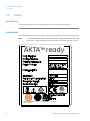
System label
The system label is located on the right side of the leg support of the ÄKTA ready cabinet.
Note:
The specific data shown on this system label is only an example. Actual data
is specific for each individual system and may vary from system to system.
ÄKTA ready
TM
Conforms to ANSI/UL Std. 61010-1 Cert. to CAN/CSA Std. C22.2 No. 61010-1
CAN ICES-1/NMB-1
24
ÄKTA ready Operating Instructions 28960345 AD
2 Safety instructions
2.2 Labels
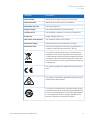
Label text
Description
Code Number
Identifies the system as being an ÄKTA ready.
System Number
Identifies the (unique) system installation.
Manufacturing Year
Manufacturing year
Supply Voltage
The voltage alternatives for ÄKTA ready.
Configured For
The voltage the system is currently configured for.
Frequency
Supply voltage frequency
Max Power Consumption
The maximum effect of the system.
Pneumatic Supply
Required pressure for pressurized air supply.
Protection Class
The electrical appliances protection classification according to international standard IEC 60529.
This symbol indicates that electrical and electronic
equipment must not be disposed of as unsorted municipal waste and must be collected separately. Please
contact an authorized representative of the manufacturer for information concerning the decommissioning
of equipment.
The system complies with applicable European directives.
The system complies with applicable requirements for
Australia and New Zealand.
This symbol indicates that the product might contain
hazardous materials in excess of the limits established
by the Chinese standard SJ/T11363-2006 Requirements
for Concentration Limits for Certain Hazardous Substances in Electronic Information Products.
ÄKTA ready Operating Instructions 28960345 AD
25
2 Safety instructions
2.2 Labels
Label text
Description
This symbol indicates that ÄKTA ready has been certified by a Nationally Recognized Testing Laboratory
(NRTL). NRTL means an organization, which is recognized by the US Occupational Safety and Health Administration (OSHA) as meeting the legal requirements
of Title 29 of the Code of Federal Regulations (29 CFR),
Part 1910.7.
Indicates that this product complies with the Canadian
standard ICES-001/NMB-001 concerning electromagnetic compatibility
Safety labels
The following table describes the various safety labels that may be found on the product.
Symbol/text
Description
Warning! Read the user documentation before using
ÄKTA ready. Do not open any covers or replace parts
unless specifically stated in the user documentation.
Warning! Pinch hazard. This sign is located next to
pinch valves and close to the pump. Never put your
fingers or any objects other than the intended tubing
in the pinch valve openings. Ensure that clothing or
other equipment do not get caught in the pinch valves.
Warning! Rotating rollers/cogwheels. This sign is located on the pump. Never touch the pump or pump lid
while the pump is running. In case of emergency, press
the emergency stop button (see Emergency shutdown,
on page 28). This immediately stops the pump.
26
ÄKTA ready Operating Instructions 28960345 AD
2 Safety instructions
2.3 Emergency procedures
2.3
Emergency procedures
In this section
This section describes how to do an emergency shutdown of ÄKTA ready and the result
in the event of power failure.
Precautions
WARNING
•
Emergency stop. Pressing the EMERGENCY STOP will not shut
off mains power to the cabinet.
•
Power failure. During a power failure, or if the EMERGENCY
STOP button is pressed, the equipment may remain pressurized. Opening a line or vessel at this point could result in the
release of potentially hazardous process or cleaning fluid, and
cause bodily harm.
When recovering from a power failure or emergency shutdown,
make sure all lines and vessels are depressurized before
opening.
•
ÄKTA ready Operating Instructions 28960345 AD
Emergency stop. Pressing the EMERGENCY STOP does not
automatically depressurize the flow path.
27
2 Safety instructions
2.3 Emergency procedures
Emergency shutdown
In a situation where there is a risk of injury, switch off the ongoing run by pressing the
EMERGENCY STOP on the front of the system cabinet. If required, also switch off the
mains power supply.
The EMERGENCY STOP immediately stops the pump motor and sets the system in pause
mode.
28
ÄKTA ready Operating Instructions 28960345 AD
2 Safety instructions
2.3 Emergency procedures
Power failure
The system power is lost if the Mains power switch on the cabinet is turned off, the
mains cable disconnected or the power supply is lost.
The pump stops if the electrical power to the system is lost. All valves will immediately
revert to default positions. Any data that has not been saved at that time may be lost.
If only the system is affected by the power failure and not the computer, UNICORN will
display text saying that communication has been broken and that no data are recovered.
When power returns to normal, the system will be in End state (i.e., it will not resume the
run).
A UPS (Uninterrupted Power Supply) protects against temporary power failures by enabling the system to continue to operate for a limited time. A UPS is not included with
the system. Contact your local GE Healthcare representative for more information about
the options for your specific system.
NOTICE
If the compressed air is lost, all inlet and outlet valves will close and
all valves at the system front will open. The pressure is let out via
the air trap. There is no risk for the user or the system, but the
product may be damaged.
Restart after emergency shut
down or power failure
Step
Action
1
Make sure that the condition that caused the power failure or emergency
stop is corrected.
2
Reset the EMERGENCY STOP button by twisting it clock-wise.
3
Press the PAUSE/CONTINUE button. The system will continue the run with
all settings intact.
ÄKTA ready Operating Instructions 28960345 AD
29
2 Safety instructions
2.4 Recycling information
2.4
Recycling information
Introduction
This section contains information about the decommisioning of ÄKTA ready.
Decontamination
The product must be decontaminated before decommissioning. All local regulations
must be followed with regard to scrapping of the equipment.
Disposal of the product
When taking the product out of service, the different materials must be separated and
recycled according to national and local environmental regulations.
Recycling of hazardous
substances
The product contains hazardous substances. Detailed information is available from your
GE Healthcare representative.
Disposal of electrical
components
Waste electrical and electronic equipment must not be disposed as unsorted municipal
waste and must be collected separately. Please contact an authorized representative
of the manufacturer for information concerning the decommissioning of the equipment.
30
ÄKTA ready Operating Instructions 28960345 AD
2 Safety instructions
2.5 Declaration of Hazardous Substances (DoHS)
2.5
Declaration of Hazardous Substances (DoHS)
根据 SJ/T11364-2014《电子电气产品有害物质限制使用标识要求》特提供如下有关污染控制方面
的信息。
The following product pollution control information is provided according to SJ/T11364-2014 Marking
for Restriction of Hazardous Substances caused by electrical and electronic products.
电子信息产品污染控制标志说明
Explanation of Pollution Control Label
该标志表明本产品含有超过中国标准 GB/T 26572 《电子电气产品中限用物质的限
量要求 》中限量的有害物质。标志中的数字为本产品的环保使用期,表明本产品
在正常使用的条件下,有毒有害物质不会发生外泄或突变,用户使用本产品不会
对环境造成严重污染或对其人身、财产造成严重损害的期限。单位为年。
为保证所申明的环保使用期限,应按产品手册中所规定的环境条件和方法进行正
常使用,并严格遵守产品维修手册中规定的定期维修和保养要求。
产品中的消耗件和某些零部件可能有其单独的环保使用期限标志,并且其环保使
用期限有可能比整个产品本身的环保使用期限短。应到期按产品维修程序更换那
些消耗件和零部件,以保证所申明的整个产品的环保使用期限。
本产品在使用寿命结束时不可作为普通生活垃圾处理,应被单独收集妥善处理。
This symbol indicates the product contains hazardous materials in excess of the limits
established by the Chinese standard GB/T 26572 Requirements of concentration
limits for certain restricted substances in electrical and electronic products. The
number in the symbol is the Environment-friendly Use Period (EFUP), which indicates
the period during which the hazardous substances contained in electrical and electronic products will not leak or mutate under normal operating conditions so that the
use of such electrical and electronic products will not result in any severe environmental pollution, any bodily injury or damage to any assets. The unit of the period is “Year”.
In order to maintain the declared EFUP, the product shall be operated normally according to the instructions and environmental conditions as defined in the product
manual, and periodic maintenance schedules specified in Product Maintenance Procedures shall be followed strictly.
Consumables or certain parts may have their own label with an EFUP value less than
the product. Periodic replacement of those consumables or parts to maintain the
declared EFUP shall be done in accordance with the Product Maintenance Procedures.
This product must not be disposed of as unsorted municipal waste, and must be
collected separately and handled properly after decommissioning.
ÄKTA ready Operating Instructions 28960345 AD
31
2 Safety instructions
2.5 Declaration of Hazardous Substances (DoHS)
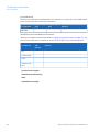
有害物质的名称及含量
Name and Concentration of Hazardous Substances
产品中有害物质的名称及含量
Table of Hazardous Substances’ Name and Concentration
List of hazardous substances
Component name
Hazardous substance
部件名称
有毒有害物质或元素
ÄKTA ready,
29-0320-38 1
1
32
Pb
Hg
Cd
Cr6+
PBB
PBDE
铅
汞
镉
六价铬
多溴联苯
多溴二苯醚
X
0
0
0
0
0
The product has not been tested as per the Chinese standard SJ/T11363-2006 Requirements for Concentration Limits for Certain Hazardous Substances in Electronic Information Product.
ÄKTA ready Operating Instructions 28960345 AD
3 System description
3
System description
About this chapter
This chapter provides an overview of the technical properties of ÄKTA ready.
In this chapter
This chapter contains the following sections:
Section
See page
3.1 Overview
34
3.2 Layout
36
3.3 Flow chart
45
3.4 Equipment
48
3.5 UNICORN control system
52
ÄKTA ready Operating Instructions 28960345 AD
33
3 System description
3.1 Overview
3.1
Overview
Intended use of ÄKTA ready
ÄKTA ready is an isocratic, low pressure, automated liquid chromatography system using
ÄKTA ready flow kits (ÄKTA ready Low Flow Kit or ÄKTA ready High Flow Kit) and ReadyToProcess columns up to 20 liter.
The system is based on proven liquid chromatography techniques, such as ion exchange,
affinity chromatography, and hydrophobic interaction.
ÄKTA ready is biocompatible and hygienic, and meets all GLP and cGMP demands for
Phase I–III in drug development and final-scale production. ÄKTA ready is controlled by
the UNICORN software.
ÄKTA ready can be equipped with an extra gradient pump in parallel to the existing
pump using ÄKTA ready gradient sections together with ÄKTA ready flow kits and
ReadyToProcess™ columns up to 20 liter. More information can be found in Chapter 7
ÄKTA ready gradient, on page 97.
ÄKTA ready is not suitable for operation in a potentially explosive atmosphere or for
handling flammable liquids.
Flow kits and columns are ordered separately. See Section 14.4 Ordering information,
on page 210 for ordering information and lists of available flow kits and columns.
WARNING
Do not operate the ÄKTA ready instrument in any other way than
described in the ÄKTA ready and UNICORN manuals.
Material compliance
All plastic and polymer materials that come in contact with buffers and samples are
compliant with USP Class VI, FDA and AFO.
Used materials are traceable back to their production batches.
You can find information about the design and materials used for your unit in the System
Documentation.
Chemical resistance is described in Section 14.3 Chemical resistance, on page 207.
34
ÄKTA ready Operating Instructions 28960345 AD
3 System description
3.1 Overview
Features
ÄKTA ready features include:
•
Liquid flow rates of up to 510 l/h.
•
4 bar operating pressure.
•
ÄKTA ready flow kits with Product Documentation. Animal free origin or equivalent
safety certification (EMEA/410/01). USP class VI material.
Areas of application
ÄKTA ready is designed for process scale-up, and small scale production. Scale-up to
production is predictable and trouble-free. In small-scale production, the system can be
used to produce purified material for clinical testing programs, or for small-scale production of diagnostic or therapeutic products.
WARNING
Flammable liquids. This product is not approved to handle
flammable liquids.
Explosive environment. The product is not approved for
work in a potentially explosive atmosphere, in areas classified as Zone 0 to Zone 2 according to IEC 60079-10 2002.
The product does not fulfill the requirements of the ATEX
Directive.
What is included in the delivery
See Section 4.1 Included in the delivery, on page 57 for a complete list.
Associated products
ÄKTA ready is intended for use with ÄKTA ready flow kits (ÄKTA ready Low Flow Kit or
ÄKTA ready High Flow Kit) and ReadyToProcess columns up to 20 l. Flow kits and columns
are ordered separately. See Chapter 14 Reference information, on page 201 for ordering
information and lists of available flow kits and columns.
ÄKTA ready Operating Instructions 28960345 AD
35
3 System description
3.2 Layout
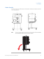
3.2
Layout
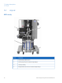
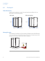
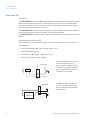
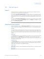
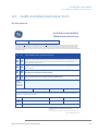
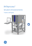
ÄKTA ready
1
2
4
3
36
Part
Function
1
ÄKTA ready cabinet unit
2
ÄKTA ready flow kit (ordered separately)
3
Column trolley
4
ReadyToProcess column (ordered separately)
ÄKTA ready Operating Instructions 28960345 AD
3 System description
3.2 Layout
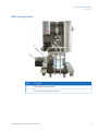
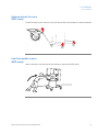
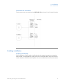
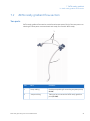
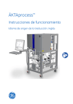
ÄKTA ready gradient
2
1
Part
Function
1
ÄKTA ready gradient pump
2
ÄKTA ready gradient flow section
ÄKTA ready Operating Instructions 28960345 AD
37
3 System description
3.2 Layout
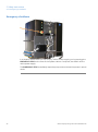
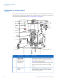
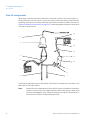
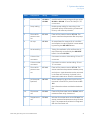
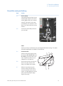
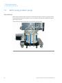
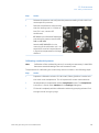
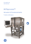
Components on system cabinet
— front
The drawing below shows the location of components on the ÄKTA ready cabinet. The
cabinet is shown without the cabinet door and with a flow kit mounted. (Components
of the flow kit are described in Flow kit components, on page 42.)
1
13
2
12
3
11
4
14
5
9
8
7
6
10
Part
Component
ID tag
Function
1
PAUSE/CONTINUE button
and alarm indicator lamp
-
Press button to pause an ongoing process.
Press again to continue. (See Pinch valves, on
page 48 for valve positions.)
RUN indicator
lamp
-
2
38
15
Lamp shows steady yellow light during pause.
Flashing yellow light indicates UNICORN
alarm.
Shows green light when system is running.
No light when system is idle (i.e., between
runs, or during pause).
ÄKTA ready Operating Instructions 28960345 AD
3 System description
3.2 Layout
Part
Component
ID tag
Function
3
POWERindicator
-
Shows flashing green light during initial communication connection with UNICORN software, when power is switched on. Steady
green light when power is on and communication is established.
4
EMERGENCY
STOP button
5
Mains power
switch
-
System mains power switch, located on the
left side of the unit.
6
Inlet valves
XV-001 to
XV-006
6 valves, located on the left side of the unit.
7
Pump
P-201
A peristaltic pump capable of delivering up
to 510 l/h of buffer and sample liquids at a
back pressure of up to 4 bar.
Stops the pump and places the system in
pause mode. (See Pinch valves, on page 48
for valve positions.)
A peristaltic pump is the simplest type of
pump, with no valves or seals that can be
clogged or corroded. The liquid is in contact
only with the bore of the tubing, eliminating
the risk of the pump contaminating the liquid,
or the liquid contaminating the pump. Peristaltic pumps can run dry.
8
Air trap valves
XV-021 to
XV-023
3-valve arrangement for air trap bypass/inline.
9
Air trap holder
-
Holder for the flow kit's air trap.
10
Column valves
XV-031 to
XV-033
3-valve arrangement for column bypass/inline.
11
Air trap vent
valve
HV-301
Manual valve controlling level in air trap.
12
AIR VENT —
Air trap ventilation button
-
Button controlling air trap ventilation through
valve HV-301. Used for releasing excess air
from air trap.
ÄKTA ready Operating Instructions 28960345 AD
39
3 System description
3.2 Layout
Part
Component
ID tag
Function
13
Installation
switch
HS-5
Used for releasing and engaging valves during flow kit and column installation. Three
different positions:
FLOW KIT INSTALL: Opens all valves. User
can manually open/close valve locks.
RUN: Engages all valves. User cannot open
safety valve locks — valves are controlled by
UNICORN.
COLUMN INSTALL: Releases valves between
airtrap outlet to column inlet. Allows for removal of air in tubing between column and
air trap.
14
Outlet valves
XV-051 to
XV-056
6 valves, located on the right side of the
chromatography unit.
15
Air filter
-
The air filter is located in a holder underneath
the system cabinet.
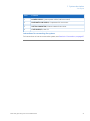
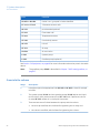
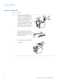
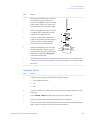
Components on system cabinet
— back
Location of connectors
Connectors for system power, pressurized air, customer I/O, and computer network are
located on the rear of the system unit, at the bottom of the cabinet:
1
40
2
3
4
ÄKTA ready Operating Instructions 28960345 AD
3 System description
3.2 Layout
Part
Function
1
POWER SUPPLY, System power cable (cable mounted)
2
PNEUMATIC AIR SUPPLY, Compressed air connector
3
SYSTEM COMPUTER, Ethernet network connector
4
CUSTOMER I/O, User I/O
Instructions for connecting the system
For instructions on how to connect the system, see Section 4.6 Connections, on page 67.
ÄKTA ready Operating Instructions 28960345 AD
41
3 System description
3.2 Layout
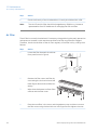
Flow kit components
ÄKTA ready uses flow kits that include all the necessary tubing, from inlet to outlet, including flow cells, air trap, column connection tubing, and pump tubing. Specifications
regarding the flow kits, including materials and chemical resistance tables, are found in
Chapter 14 Reference information, on page201. The drawing below shows the components
of an ÄKTA ready flow kit.
14
5
15
4
13
12
3
11
2
10
1
9
8
6
7
The following table gives a brief description of the flow kit components. Numbers in the
table refer to the figure above.
Note:
42
Several flow kit components are flow cells for sensors located on the system
cabinet. In such cases, the ID tag technically refers to the sensors rather than
the flow cells/adapters. Here, however, the tags are used for identification of
both sensors and their corresponding flow cells.
ÄKTA ready Operating Instructions 28960345 AD
3 System description
3.2 Layout
Part
Component
ID tag
Function
1
Inlet manifold
XV-001 to
XV-006
Manifold with 6 inlets corresponding to valves
XV-001 to XV-006. 25 mm TRI-Clamp™ (TC)
connectors.
2
Pump tubing
-
Double pump tubing for mounting in the
peristaltic pump. Double tubing increases efficiency and reduces pulsation.
3
Flow cell for
pressure sensor
PT-111
Flow cell for pressure sensor PT-111. The
sensor measures the pressure after the pump.
4
Air trap
AT-221
Air trap allows for removal of air in buffers
and sample. Air trap is filled (air is evacuated)
by pressing the AIR VENT button.
5
Air vent tubing
-
Tubing for ventilation of air to/from the air
trap. (Manually controlled by the AIR VENT
button via valve HV-301.)
6
Column inlet
connector
-
Connector to column inlet tubing. 25 mm TC
connector.
7
Column outlet
connector
-
Connector to column outlet tubing. 25 mm
TC connector.
8
Flow cell for
pressure sensor
PT-112
Flow cell for pressure sensor PT-112. The
sensor measures the pressure between pump
and column. A pH electrode can be mounted
in the flow cell. (A dummy is placed in the
electrode holder when flow kit is delivered.)
9
pH electrode
(optional)
AE-121
Sensor measuring pH of the liquid. Can be
mounted in flow cell for pressure sensor PT112.
See information about sanitization below table.
10
Flow meter
cell
FE-141
Flow cell for flow meter sensor FE-141, which
measures flow using ultrasound.
11
Temperature
cell
TE-161
Window for temperature sensor TE-161. The
sensor measures temperature using infrared
light. The temperature window is integrated
with the flow meter cell.
ÄKTA ready Operating Instructions 28960345 AD
43
3 System description
3.2 Layout
Part
Component
ID tag
Function
12
Conductivity
sensor
CE-101
Sensor measuring the conductivity of the liquid.
13
UV flow cell
AE-131
Flow cell for UV detector AE-131.
14
Flow cell for
pressure sensor
PT-113
Flow cell for safety pressure sensor PT-113,
which measures pressure after the sensors.
15
Outlet manifold
XV-051 to
XV-056
Manifold with 6 outlets corresponding to
valves XV-051 to XV-056. 25 mm TC connectors.
Sanitization
Except for the pH electrode, all parts of the flow kit are sanitized at delivery, either through
gamma radiation (inlet manifold and main part of flow kit) or autoclaving (pump tubing).
The pH electrode should be sanitized by the user.
44
ÄKTA ready Operating Instructions 28960345 AD
3 System description
3.3 Flow chart
3.3
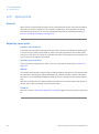
Flow chart
Chart and components
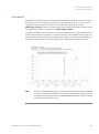
The liquid flow through ÄKTA ready is illustrated in the chart below.
(Black: standard components; Red: optional components)
A
B
C
D
HV-301
P-202
PT-111
XV-001
XV-002
XV-003
XV-004
XV-005
XV-006
XV-056
XV-055
XV-054
XV-053
XV-052
XV-051
AT-221
PT-112 FE-141 CE-101 PT-113
P-201
AE-121 TE-161 AE-131
The table below specifies the maximum operating pressure the flow path could be
pressurized to with the pressure upgrade strategy in the different parts of the system.
Part
Description
Pressure
A
Low pressure, over the Inlet Manifold
0.6 bar
B
High pressure, over the air trap manifold and column
5.0 bar
C
Medium pressure
2.0 bar
D
Medium pressure, over the outlet manifold
0.95 bar
The table below describes the system components shown in the flow chart.
Part
Function
XV-001 to XV-006
Inlet 1 to 6, grouped in Inlet Manifold
ÄKTA ready Operating Instructions 28960345 AD
45
3 System description
3.3 Flow chart
Part
Function
XV-051 to XV-056
Outlet 1 to 6, grouped in Outlet Manifold
PT-111 to PT-113
3 Pressure sensors cells
AE-121
pH electrode (optional)
FE-141
Flow meter cell
TE-161
Temperature sensor
CE-101
Conductivity sensor
AE-131
UV cell
AT-221
Air trap
HV-301
Air vent valve
P-201
System pump
P-202
Gradient pump (optional)
See Section 3.4 Equipment, on page 48 for more information about the parts in the table
above.
Note:
The gradient pump (P202) is described in Chapter 7 ÄKTA ready gradient, on
page 97.
From inlet to column
46
Stage
Description
1
Inlet valves open the appropriate inlet (XV-001 to XV-006 in chart) for sample
or buffer.
2
The system pump (P-201) and the gradient pump (P-202) deliver the liquid
to the column via a pressure sensor cell (PT-111) and, if preferred, via the
air trap (AT-221), where air in the liquid is removed.
3
There are two sets of valves between the pump and the column:
•
the air trap manifold, which allows for bypassing the air trap, and
•
the column manifold, which allows for bypassing the column.
ÄKTA ready Operating Instructions 28960345 AD
3 System description
3.3 Flow chart
From column to outlet
Stage
Description
1
Downstream of the column, the liquid passes through a second pressure
sensor cell (PT-112), which has an integrated flow cell for a pH electrode
(AE-121).
2
The liquid then continues through:
•
a flow meter cell (FE-141) with integrated temperature sensor (TE-161),
•
a conductivity cell (CE-101), and
•
a UV cell (AE-131).
3
The last sensor in the path is a third pressure sensor (PT-113).
4
Downstream from the sensors, the liquid continues via the outlet tubing to
the outlet manifold, where valves (XV-051 to XV-056) divert the liquid to either
waste or fraction collection.
Maximum pressures
•
At the outlet manifold, the system works under a pressure of max 0.95 bar.
•
Between pump and column the pressure is max 5 bar.
•
Between column and outlet manifold the pressure is max 2 bar.
•
The different pressure zones are monitored by pressure sensors PT-111 to PT-113.
ÄKTA ready Operating Instructions 28960345 AD
47
3 System description
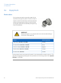
3.4 Equipment
3.4
Equipment
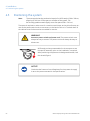
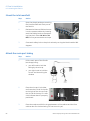
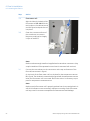
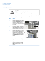
Pinch valves
Pinch valves are used to control the path of the
liquid flow through the system. There are 19 pinch
valves in total. The valves have manually operated
safety locks keeping the tubing in place and preventing the valves from accidentally closing during
flow kit installation.
WARNING
Never put fingers or any objects other than the intended tubing in
to the pinch valve opening.
Valves
Default position
Inlet valves, XV-001 to XV-006
Closed
Air trap valves, XV-021 to XV-023
Inline
Column valves, XV-031 to XV-033
Bypass
Outlet valves, XV-051 to XV-056
Closed
Air Vent Valve, HV-301
Closed
During pause, the air trap valves will remain in the same position as during the run. The
user can change this by setting the air trap valves to inline during pause, in the System
Settings in UNICORN.
48
ÄKTA ready Operating Instructions 28960345 AD
3 System description
3.4 Equipment
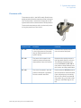
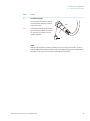
Pressure cells
The pressure cells in the ÄKTA ready flow kits are
designed with a flexible membrane that is brought
into contact with a transducer (load cell) on the
system cabinet for measurement of fluid pressure.
There are three pressure cells, continuously measuring the pressure of the liquid:
Pressure cell
Location
Function
PT-111
The first pressure cell is located
in the high pressure flow path,
directly downstream from the
system pump.
Measures the total pressure
over the entire flow path.
PT-112
The second is located in the
medium pressure flow path,
downstream from the column.
Measures the total pressure in
the flow path after the column.
The difference between pressures at PT-111 and PT-112 is
the pressure drop (Delta p) over
the column and the packed bed.
PT-113
The third is located in the low
pressure flow path, upstream
from the outlet manifold.
Pressure sensor PT-113 protects
the low pressure outlet manifold
from overpressure, caused by
failure in the fluid lines outside
the system (e.g., pinched outlet
tubing or overfilled bag at outlet).
ÄKTA ready Operating Instructions 28960345 AD
49
3 System description
3.4 Equipment
pH electrode (optional)
The pH electrode, AE-121, is an optional accessory (see Section 14.4 Ordering information,
on page 210). The electrode can be mounted in a holder on top of pressure cell PT-112.
When a flow kit is delivered, a dummy is located in the pH electrode holder. Unlike the
rest of the flow kit, the pH electrode has not been autoclaved or subjected to gamma
radiation at delivery and must therefore be cleaned by the user.
The pH electrode should be calibrated at least once a day (see pH calibration, on page186).
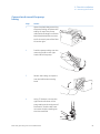
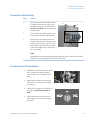
Flow meter cell
The flow meter cell, FE-141, is placed after the pressure cell PT-112/pH electrode AE-121
in the flow path. The flow meter measures the liquid velocity using ultrasound. Transducers are connected to both sides of a straight channel through the cell. The difference
between upstream and downstream ultrasound velocity is measured and the result is
used to compute the flow. In order to ensure proper transmission of the sound energy,
the contact surfaces should be coated with a thin layer of Vaseline™ delivered with the
flow kit or similar lubricant before the transducers are connected.
Air sensor
The air sensors, AE-151 and AE-152, are high precision monitors designed for continuous
monitoring of air bubbles in the flow path. When air is detected, the system is either
paused, or performs an action that is set in the method.
Temperature sensor
The temperature sensor, TE-161, is located on the front of the system cabinet, beneath
the flow meter cell. The sensor measures the infrared radiation emitted from a dedicated
measurement window in the body of the flow meter cell. A lens in front of the sensor
focuses the infrared radiation.
Note:
50
A system that is not properly temperature equilibrated may produce incorrect
temperature readings. Therefore, if the system or flow kit is moved between
rooms with different temperatures, time must be allowed for the equipment
to adjust to the new ambient temperature. In particular, the body of the flow
meter cell may need several hours to adjust to room temperature.
ÄKTA ready Operating Instructions 28960345 AD
3 System description
3.4 Equipment
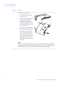
Conductivity sensor
The conductivity sensor, CE-101, is included with the flow kit (for all other sensors, the
flow kit includes only the flow cells). The conductivity sensor is located after the flow
meter cell in the flow path. It is primarily used to verify the conductivity of buffer solutions.
Conductivity measurement is temperature compensated and thus dependent on correct
temperature readings. The conductivity sensor cable is connected to the system cabinet
using a screw-on connector secured by a fastening nut. The standard setting of the cell
constant is 12.5 cm-1.
UV cell
The UV cell, AE-131, is located after the conductivity cell in the flow path. The cell consists
of a transparent rectangular flow cell. The cell is mounted in a holder containing a UV
LED emitting at 280 nm and two detectors measuring the UV absorbance of the liquid.
For correct measurements it is important that UV cell and sensor windows are properly
fitted, kept clean and dry. The temperature of the process liquid must not be lower than
10ºC from the ambient temperature. Otherwise there is a risk for condensation of
moisture on the flow cell window.
ÄKTA ready Operating Instructions 28960345 AD
51
3 System description
3.5 UNICORN control system
3.5
UNICORN control system
Overview
ÄKTA ready is controlled by UNICORN process control software. ÄKTA ready can be
controlled by both UNICORN 5 and UNICORN 7.
UNICORN can save established processes as methods. The methods include the
instructions necessary for process operation and documentation.
UNICORN includes a comprehensive system of user access levels to be programmed
limiting the operations a given user may perform on ÄKTA ready. To secure safe operation
of the system, you should limit access to the system to those qualified and trained in its
operation.
The UNICORN software wizards and the UNICORN user documentation provide complete
instructions for programming and for using the software for process control.
System operators are responsible for designing methods which conform to standard
operating procedures and Good Manufacturing Practice procedures.
UNICORN is compliant with FDA 21 CFR Part 11.
Knowledge prerequisite
At least basic knowledge of UNICORN is expected to operate ÄKTA ready in a safe
manner.
Information on how to use UNICORN can be obtained from the UNICORN documentation
and available tutorials. This manual does not cover how to use UNICORN.
Contact your local GE Healthcare representative for advice if required.
System networks
UNICORN can be installed on a stand-alone computer to control one to four locally
attached systems. However, the computer can only show one system at a time. Multiple
computers can view the output data from one system. UNICORN can also be installed
on a network.
52
ÄKTA ready Operating Instructions 28960345 AD
3 System description
3.5 UNICORN control system
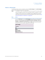
Software modules
The UNICORN control software consists of four modules:
Module
Function
In UNICORN 5: UNICORN Manager
File handling and administration tasks; for example, definition of systems and managing
user profiles.
In UNICORN 7: Administration
Method Editor
Method creation and editing for preprogrammed control of ÄKTA ready.
System Control
Process online control and monitoring using
pre-defined methods or manual control.
Evaluation
Evaluation and presentation of stored results.
Note:
The modules are active when the program is operating and are not closed
when minimized. A minimized System Control unit may control a process.
Workflow
The workflow for using UNICORN system for automatic control includes these general
steps:
Step
Action
1
Program an ÄKTA ready method run using the UNICORN software. It is possible to use an existing method or modify an existing method to meet your
run objectives.
2
Start the run using the method you created.
3
Monitor the run's progress using the System Control module. All the data
about your run is displayed in the System Control module. You have a choice
of four different panes that can be open one at a time or all at once, in separate parts of the window.
4
After completing the run, you can display the data in a detailed report using
extensive tools provided by the UNICORN Evaluation Module.
Warnings
Warnings are generated to warn operating personnel that process parameters have
exceeded preset high and/or low limits, and that the process method continues.
ÄKTA ready Operating Instructions 28960345 AD
53
3 System description
3.5 UNICORN control system
Alarms
Signals
If equipment is connected that has lower limits than the system, the alarm levels must
be set accordingly.
If an analog or digital signal passes the predetermined alarm level, several things happen
at once:
•
The system is set to Pause mode.
•
The valves and other components on the system are set to their default positions.
The Valve Pause Function can be enabled in UNICORN for certain components (air trap,
column) to retain the original valve positions.
Test
To test a specific instrument alarm it is possible to lower the alarm limit for the instrument
below the current process value.
Reset
The alarm is reset through the control system by acknowledging the alarm message.
The process can be started again using the Continue function in UNICORN, if the situation
has been rectified.
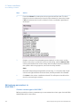
Differences between UNICORN 5
and UNICORN 7
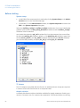
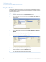
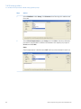
In UNICORN 5 you start the three installation wizards (Flow Kit Installation with Component Test, Troubleshoot Failed Component Test and Column Installation) by clicking
Instant Run on the File menu in the System Control module.
In UNICORN 7 you start the same wizards by clicking New Method on the File menu in
the Method Editor module. The installation wizard will create a method that you must
save and then run in the System Control module.
The content of these methods are the same for UNICORN 5 and UNICORN 7. They are
described in Chapter 6 Flow kit installation, on page 77, Section 8.3 Troubleshooting a
failed component test, on page 117 and Chapter 9 Column installation, on page 122.
Note:
54
In UNICORN 5 there is limited method editing support from the column list in
UNICORN. In UNICORN 7 the user must enter column parameters manually,
see Edit column parameters in UNICORN 7, on page 130.
ÄKTA ready Operating Instructions 28960345 AD
4 Installation
4
Installation
About this chapter
This chapter describes how to transport and install ÄKTA ready.
ÄKTA ready is designed for ease-of-use. As a consequence, the system is easy to install
and setup for the first run. Most of the components are mounted on the system cabinet
or on the flow kit.
There are few loose parts that require assembling or mounting, and the physical connections are simple and straightforward. Installation should, however, always be performed
by experienced personnel authorized by GE Healthcare.
Apart from a suitable environment for the instrument, the prerequisites for installation
of ÄKTA ready include outlets for electrical power and compressed air, and access to a
computer. Some tools are required for unpacking the instrument, and test liquids must
be prepared.
Precautions
WARNING
Before attempting to perform any of the procedures described in
this chapter, you must read and understand all contents of the
corresponding section(s) in the Section 2.1 Safety precautions, on
page 15 as listed below:
•
Installing and moving, on page 17
•
Personal protection, on page 16
NOTICE
ÄKTA ready shall be installed and prepared by personnel from GE
Healthcare or third party authorized by GE Healthcare.
Contact GE Healthcare if you require re-installation at a new site.
ÄKTA ready Operating Instructions 28960345 AD
55
4 Installation
In this chapter
This chapter contains the following sections:
Section
56
See page
4.1 Included in the delivery
57
4.2 Site requirements
58
4.3 Transport
60
4.4 Unpacking
65
4.5 Positioning the system
66
4.6 Connections
67
ÄKTA ready Operating Instructions 28960345 AD
4 Installation
4.1 Included in the delivery
4.1
Included in the delivery
General
ÄKTA ready is delivered in a wooden box containing:
•
the system cabinet,
•
a column trolley,
•
a smaller box containing an accessory kit, system documentation folder and user
documentation.
The accessory kit
The accessory kit delivered with the system contains:
•
Bar code scanner (USB),
•
two computer network cables (10 and 3 m), and a RJ45 coupling connector,
•
key for the back door of the system cabinet,
•
compressed air tubing (5 m),
•
customer I/O connector,
•
CD disks containing UNICORN and ÄKTA ready strategy software,
•
documentation, including UNICORN and ÄKTA ready manuals,
•
system log book,
•
labels for configured voltage.
A 10 mm wrench for the bolts holding the pump lid is also located on the inside of the
front cabinet door.
Associated products
ÄKTA ready gradient pump is optional and used together with the ÄKTA ready gradient
flow section.
ÄKTA ready is intended for use with ÄKTA ready flow kits (ÄKTA ready Low Flow Kit or
ÄKTA ready High Flow Kit) and ReadyToProcess columns up to 20 L.
Flow kits and columns are ordered separately. See Chapter 14 Reference information,
on page 201 for ordering information and lists of available flow kits and columns.
ÄKTA ready Operating Instructions 28960345 AD
57
4 Installation
4.2 Site requirements
4.2
Site requirements
Precautions
WARNING
Explosive environment. The product is not approved for work in
a potentially explosive atmosphere, in areas classified as Zone 0
to Zone 2 according to IEC 60079-10 2002. The product does not
fulfill the requirements of the ATEX Directive.
CAUTION
•
Do not use the product in a dusty atmosphere or close to
spraying water.
•
The product is designed for indoor use only.
Dimensions of ÄKTA ready
Property
ÄKTA ready
ÄKTA ready gradient
Width / Depth / Height
100 × 80 ×165 cm
116 x 80 x 165 cm
Weight
230 kg
250 kg
Ambient environment
58
•
Relative air humidity 20% to 95%, non-condensing.
•
Particle free (filtered) air.
•
Clean and dust-free environment.
•
Temperature +2ºC to +30ºC (-25ºC to +60ºC for storage).
•
Atmospheric pressure 950-1050 mbar.
ÄKTA ready Operating Instructions 28960345 AD
4 Installation
4.2 Site requirements
Compressed air
•
Dry and particle free air
•
Airflow 50 Nl/min
•
Working pressure 5.5 to 10 bar
•
Air hose connector, a 5 m long air hose with an inner diameter of 7.5 mm is supplied
with the system.
Electrical power
•
Delivered with a permanent power cable, equipped with an IEC 60309 connector.
•
Preconfigured for 230V 50/60 Hz AC power supply.
See Section 4.6 Connections, on page 67 for instruction on how to reconfigure the power
supply.
ÄKTA ready Operating Instructions 28960345 AD
59
4 Installation
4.3 Transport
4.3
Transport
Crate dimensions
The ÄKTA ready is delivered in a crate. The crate dimensions are different if it is an
ÄKTA ready or an ÄKTA ready gradient.
ÄKTA ready
ÄKTA ready gradient
190 cm
190190
cm cm
110 cm
115 cm
110 110
cm cm
190 cm
135135
cmcm
Moving the crate
Use a pallet jack or forklift with a minimum capacity of 400 kg to move and lift ÄKTA ready
in the crate. Make sure that intended openings and apertures are large enough to allow
passage of the crate when lifted from the floor for transport.
>400 kg
60
ÄKTA ready Operating Instructions 28960345 AD
110 c
4 Installation
4.3 Transport
Release wheels to move
ÄKTA ready
The ÄKTA ready can be rolled on hard and level surface with brakes on wheels released.
Use the handle to move
ÄKTA ready
Use the handle on the left side of the cabinet to maneuver ÄKTA ready.
ÄKTA ready Operating Instructions 28960345 AD
61
4 Installation
4.3 Transport
Lifting ÄKTA ready
There are no lifting hooks on ÄKTA ready. Use a forklift or a pallet jack with a minimum
capacity of 400 kg for lifting the system. Appropriate safety precautions should be followed.
CAUTION
Do not attempt to lift the system by the handle on the left side of
the system cabinet. The handle is for maneuvring the cabinet on
the floor, not for lifting.
62
ÄKTA ready Operating Instructions 28960345 AD
4 Installation
4.3 Transport
Center of gravity
The center of gravity for ÄKTA ready is indicated with a dashed and dotted, vertical line
in the drawings below.
Note:
The line is located slightly towards the back of the cabinet. This must be taken
into consideration when moving or lifting the cabinet.
ÄKTA ready Operating Instructions 28960345 AD
63
4 Installation
4.3 Transport
Positioning forks
•
EU
`
•
64
US
ÄKTA ready Operating Instructions 28960345 AD
4 Installation
4.4 Unpacking
4.4
Unpacking
Check for damage
Check the equipment for damage before starting assembly and installation. There are
no loose parts in the crate. All parts are either mounted on the system or located in the
accessory kit box. If any damage is found, document the damage, and contact your local
GE Healthcare representative.
Safety Precautions
WARNING
Personal Protective Equipment (PPE). Whenever packing, unpacking, transporting or moving ÄKTA ready, wear:
•
Protective footwear, preferably with steel lining.
•
Working gloves, protecting against sharp edges.
•
Protective glasses.
WARNING
Because of the significant weight of ÄKTA ready, great care must
be taken not to cause squeezing or crushing injuries during
movement. It is recommended that two persons move the system.
WARNING
At least two persons are required to unpack ÄKTA ready gradient!
Instructions for unpacking
For a full description of how to unpack ÄKTA ready refer to the following unpacking instructions:
•
ÄKTA ready Unpacking instructions, article number 28-9944-89, and
•
ÄKTA ready gradient Unpacking instructions, article number 29-0420-82
ÄKTA ready Operating Instructions 28960345 AD
65
4 Installation
4.5 Positioning the system
4.5
Positioning the system
Note:
The area required at the production location for ÄKTA ready is 280 x 300 cm,
allowing for 100 cm of free space on all sides of the system. The
ÄKTA ready gradient needs slightly more free space (280 x 316 cm).
The space is required to make room for containers and hoses, and to allow for easy access to the power switch and to connectors on the back of the unit. The back door of
the cabinet must furthermore be accessible for service.
WARNING
Access to power switch and power cord. The power switch must
always be easy to access. The power cord must always be easy to
disconnect.
ÄKTA ready arrives preassembled in the transport crate.
No specific assembly prior to site installation is required.
After positioning the system at its designated location, lock
the wheels (figure).
NOTICE
Check that the Pressure Control Regulator for the system air supply
is set to the pressure stated in the specifications.
66
ÄKTA ready Operating Instructions 28960345 AD
4 Installation
4.6 Connections
4.6
Connections
Connector locations
A cable for system power is permanently mounted on the back of the system cabinet.
Connectors for pressurized air, computer network and customer I/O are are also located
on the back of the system unit, at the bottom of the cabinet. Two computer network
cables, and a connector for the customer I/O are supplied but not mounted. For more
information about connector locations, see Components on system cabinet — back, on
page 40.
Power
WARNING
High voltage. The mains cable must only be connected by authorized service personnel. Faulty connection might result in live system
parts that can give lethal electric shocks.
NOTICE
Do not turn on the Mains power switch before all connections are
made.
Power connection
The mains power supply must be connected and configured by authorized service personnel. Please contact your GE Healthcare representative.
Compressed air
NOTICE
Check that the Pressure Control Regulator for the system air supply
is set to the pressure stated in the specifications.
ÄKTA ready Operating Instructions 28960345 AD
67
4 Installation
4.6 Connections
CAUTION
Make sure that correct air pressure is always maintained. Too high
or too low air pressure may be hazardous and may cause erroneous
results and leakage.
Instruction
68
Step
Action
1
Connect your compressed air supply to the air input connector on the back
of the system, labeled PNEUMATIC AIR SUPPLY. Use the supplied 5 m air
hose with inner diameter 7.5 mm.
2
Switch on the air supply.
3
Check for air leaks.
ÄKTA ready Operating Instructions 28960345 AD
4 Installation
4.6 Connections
Computer
Requirements
WARNING
Installing the computer. The computer must be installed and used
according to the instructions provided by the manufacturer of the
computer.
UNICORN is the controlling software for ÄKTA ready. It is recommended that the computer
used is dedicated to UNICORN and related software. Due to the risk for computer viruses,
it is also recommended that the computer is not directly connected to Internet.
See the UNICORN manuals for further details about software requirements and installation.
Instruction
Two network cables are delivered with the system and should be connected according
to the instruction below:
Step
Action
1
Connect the encapsulated end of the longer (10 m) straight cable to to the
connector (of type RJ45) marked SYSTEM COMPUTER on the back of the
system.
2
Connect the other end of the long cable to:
Note:
•
the controlling computer if a direct connection is used, or
•
the shorter (3 m) crossover cable, which, in turn, is connected to a switch
or hub (the shorter cable is only used when connecting to the controlling
computer via a network).
In order not to compromise the protection of the cabinet, use only the enclosed
communication cables.
ÄKTA ready Operating Instructions 28960345 AD
69
4 Installation
4.6 Connections
Customer I/O
Connector
The CUSTOMER I/O connector (C1 in figure below) is located on the left side of the system
cabinet, beneath the inlet valves. The connector is a 15-pole IP67-proof Dsub male
connector. A female mating connector containing a screw terminal block with water
tight housing is supplied with the system.
The CUSTOMER I/O connector can be used for an external alarm, and to receive a signal
indicating that a UPS has been activated. This is described below.
The CUSTOMER I/O connector is also used for connecting the air sensors, as described
below.
Connection for alarm or UPS
Input voltage is 24 V (acceptable range 15 to28 V), and output signal is 24 V/max 1 A.
The signals are:
•
Pin 1: Remote Alarm (A in figure) digital output +24 V
•
Pin 4: GND, Digital ground
•
Pin 11: UPS On (B in figure), digital input (+24 V)
•
Pin 15: +24 V Digital Supply voltage.
ÄKTA ready
A
+24 V
C1
1
Pins 1 and 4 provide an output
for an alarm device (e.g., a
warning light, a buzzer, or similar device). The external alarm
will be triggered when the internal buzzer is activated.
4
ÄKTA ready
C1
15
B
70
+24 V
Pins 11 and 15 are used to receive an On signal (B in figure)
from an (optional) UPS during a
power failure.
11
l
ÄKTA ready Operating Instructions 28960345 AD
4 Installation
4.6 Connections
Connection for air sensors
The air sensors are connected to the CUSTOMER I/O as shown in the illustration below.
Finishing installation
Verifying connections
Finish installation of ÄKTA ready by verifying that the system is properly connected to
mains power, to compressed air supply, and to the computer. Next, verify that communication between UNICORN and the system unit can be established, see instruction below.
ÄKTA ready Operating Instructions 28960345 AD
71
4 Installation
4.6 Connections
Establishing computer connection
Step
Action
1
Turn on ÄKTA ready using the Mains power switch, located on the left side
of the cabinet.
Check that the green POWER lamp on the front of the unit lights up (bottom
lamp in figure). The light flashes slowly when communication with UNICORN
is not established.
2
Switch on the computer and computer screen, and check that a booting
process starts.
3
After booting is finished, check that the UNICORN software is installed and
available (UNICORN symbol visible on the computer’s desktop).
Start UNICORN by double-clicking its icon.
4
72
Check that the green POWER lamp now shows a steady green light, indicating that UNICORN recognizes and can communicate with the system unit.
ÄKTA ready Operating Instructions 28960345 AD
4 Installation
4.6 Connections
Installing the barcode reader
The barcode reader is installed and configured as described below.
Note:
Installation requires barcodes to be scanned from the Quick Start Guide supplied with the barcode reader. If the Quick Start Guide is lost, it can be downloaded from the barcode reader manufacturer's web site.
Step
Action
1
Connect the barcode reader to the computer with a USB cable, as shown
in the Quick Start Guide.
2
Locate the USB Keyboard (PC) interface barcode in the Quick Start Guide
and scan it using the barcode reader.
3
Place the barcode reader in its holder. The installation is complete when it
beeps.
4
To verify the barcode function, open an empty Notepad document (type
notepad in the Start menu search field, click the Notepad item that is dis-
played as the search result). Scan any barcode. A text string should appear
in the Notepad document.
The Notepad document may be discarded.
5
If the barcode reader does not function, locate the Standard Products Default barcode in the Quick Start Guide and scan it with the barcode reader.
Repeat the installation procedure.
ÄKTA ready Operating Instructions 28960345 AD
73
5 Starting ÄKTA ready
5
Starting ÄKTA ready
About this chapter
This chapter describes how to start and log on to UNICORN and ÄKTA ready.
Precautions
WARNING
Before attempting to perform any of the procedures described in
this chapter, you must read and understand all contents of the
corresponding section(s) in the Section 2.1 Safety precautions, on
page 15 as listed below:
•
General precautions, on page 15
In this chapter
This chapter contains the following sections:
Section
74
See page
5.1 Start and log on to UNICORN
75
5.2 Start the system
76
ÄKTA ready Operating Instructions 28960345 AD
5 Starting ÄKTA ready
5.1 Start and log on to UNICORN
5.1
Start and log on to UNICORN
UNICORN software
The UNICORN control software is delivered with the system. UNICORN should be installed
on a PC (optional) with Microsoft Windows operating system. Refer to the UNICORN
manuals for software installation instructions.
Starting UNICORN
See Alarms, on page 54 for more information regarding the UNICORN control system,
warnings and alarms.
Step
Action
1
Switch on the computer.
2
Log on to Windows.
3
Start UNICORN by double-clicking on the UNICORN icon on
the Windows desktop.
4
When the Logon dialog box appears, select a user from the Users list and
enter the password.
If you log on for the very first time, select the user default and enter the
password default.
5
Click OK.
6
In the System Control module, on the System menu, click Connect.
7
In the dialog shown, select the appropriate system name and click OK. The
system name is specified during installation configuration.
8
When UNICORN is connected to the system, the Run button in the status
bar is enabled. The button initially has a green color indicating the system
is ready to run.
ÄKTA ready Operating Instructions 28960345 AD
75
5 Starting ÄKTA ready
5.2 Start the system
5.2
Start the system
General
ÄKTA ready is normally left switched on between runs. The unit is switched off only during
monthly maintenance and repair, or when not in operation for a longer period of time
(more than a few days).
Starting ÄKTA ready
Step
Action
1
Switch on power to ÄKTA ready by turning the Mains Power switch to the
"I" position. See Components on system cabinet — front, on page 38 for location.
2
Make sure that UNICORN is started according to the instruction above. Wait
for connection.
After this sequence is completed, the following occurs:
•
The POWER indicator lamp flashes. See Components on system cabinet — front, on
page 38 for location.
•
When communication with UNICORN software is established, the POWER indicator
lamp shows a steady green light.
Note:
76
When power is switched on ÄKTA ready will perform a stray light calibration
without the UV flow cell installed. This will result in a very high calibration
factor. Therefore it is very important to perform a stray light calibration as
soon as the flow kit is mounted and water or any other actual liquid has been
purged through the flow kit.
ÄKTA ready Operating Instructions 28960345 AD
6 Flow kit installation
6
Flow kit installation
About this chapter
This chapter presents the different flow kits that can be used with the ÄKTA ready, and
describes how to install an ÄKTA ready flow kit. Much of the information in this chapter
is also available in the ÄKTA ready installation wizard (part of supplied software). How
to install the gradient flow section is described in Section 7.2 ÄKTA ready gradient
flow section, on page 99.
Precautions
WARNING
Before attempting to perform any of the procedures described in
this chapter, you must read and understand all contents of the
corresponding section(s) in the Section 2.1 Safety precautions, on
page 15 as listed below:
•
General precautions, on page 15
•
Flammable liquids and explosive environment, on page 17
•
Personal protection, on page 16
•
Operation, on page 19
In this chapter
This chapter contains the following sections:
Section
See page
6.1 ÄKTA ready flow kits
78
6.2 Unpacking the flow kit
80
6.3 Mounting the flow kit
81
ÄKTA ready Operating Instructions 28960345 AD
77
6 Flow kit installation
6.1 ÄKTA ready flow kits
6.1
ÄKTA ready flow kits
Three parts
ÄKTA ready flow kits are delivered in three parts. Each of the three parts constituting the
flow path are sanitized and ready for use with the ÄKTA ready.
3
2
1
No.
Part
Function
1
Inlet manifold
Tubing with 6 connectors for inlets and one for
the pump tubing.
2
Pump tubing
Double pump tubing for mounting in the peristaltic
pump, with connectors to inlet tubing and to the
main part of the flow kit tubing.
3
Main part
Tubing with all required flow cells (pressure, flow
meter, temperature, conductivity, and UV), air trap,
6 outlets, and connectors to pump tubing and
column.
Note:
The pH electrode is optional. For ordering information, see Section 14.4 Ordering information, on
page 210.
78
ÄKTA ready Operating Instructions 28960345 AD
6 Flow kit installation
6.1 ÄKTA ready flow kits
It is possible to assemble a flow kit before it is mounted onto the system cabinet. The
recommended procedure, however, is to connect the three parts to each other in connection with mounting of the flow kit. This is the procedure described in this chapter.
Flow kit types
Two different ÄKTA ready flow kits are available:
•
ÄKTA ready High Flow Kit, with tubing diameter 9.5 mm (inlet manifold 12.7 mm,
pump tubing 12 mm). Intended for 10 to 20 liter ReadyToProcess columns.
•
ÄKTA ready Low Flow Kit, with tubing diameter 6.4 mm (inlet manifold 9.5 mm, pump
tubing 8 mm). Intended for columns with a volume of less than 10 liters.
Both flow kits use 25 mm TC connectors for connecting to inlet and outlet containers,
pump tubing, and column.
NOTICE
Only use flow kits, supplied by GE Healthcare.
Specifications for ÄKTA ready flow kits are found in ÄKTA ready flow kit specifications,
on page 203. Ordering information is in ÄKTA ready flow kits, on page 210.
ÄKTA ready Operating Instructions 28960345 AD
79
6 Flow kit installation
6.2 Unpacking the flow kit
6.2
Unpacking the flow kit
Flow kit package
To protect against contamination, ÄKTA ready flow kits are delivered in double plastic
bags.
The flow kit package contains the following items:
•
The main part of the flow kit and the inlet manifold (6 inlets). The main part includes
air trap, column connection tubing, sensor flow cells, and outlet manifold (6 outlets).
•
The pump tubing, including 2 TC clamps with gaskets.
•
Vaseline.
•
A binder containing product documentation for the flow kit.
Unpack flow kit
Unpack ÄKTA ready flow kits as follows:
Step
Action
1
Cut open the outer plastic bag in a clean environment near the ÄKTA ready,
for example in the air lock, if the system is in a clean room.
2
Take out the inside plastic bags and move them together with the other flow
kit equipment to the system cabinet. Open the bags immediately before
mounting the flow kit onto the system cabinet.
Note:
In addition to the plastic wrappings, ÄKTA ready flow kits are equipped with
plastic end caps protecting the connectors from contamination. Do not remove
any of the end caps until it is time to connect the flow kit to buffer bags/tanks
and to column, which are the last steps in the mounting procedure (see Section 6.3 Mounting the flow kit, on page 81 and Section 9.2 Installing a column,
on page 127).
Labeling of flow kits
The different parts of the ÄKTA ready flow kits are labeled and equipped with bar codes.
The bar codes are primarily used for traceability. ReadyToProcess Columns have bar
codes for the same purpose.
80
ÄKTA ready Operating Instructions 28960345 AD
6 Flow kit installation
6.3 Mounting the flow kit
6.3
Mounting the flow kit
Introduction
This section contains a step-by-step description of how to install a flow kit onto the
ÄKTA ready cabinet. The procedure described here is an extended version of the procedure described in the Flow Kit Installation part of the ÄKTA ready Installation Wizard.
There is, however, no direct correspondence between the numbering of the steps in the
wizard and the numbering used here.
You are recommended to always use the wizard when installing a new flow kit. It helps
to ensure that all the steps are performed, and performed in the right order. The wizard
thereby provides a simple way of securing the correctness of a flow kit installation. The
wizard also includes a component test and provides the option of producing a printed
report containing installation information and test results.
ÄKTA ready Operating Instructions 28960345 AD
81
6 Flow kit installation
6.3 Mounting the flow kit
Before starting
System setup
•
In UNICORN 5 the component list is reached by clicking System Setup on the Administration menu in the UNICORN Manager
•
In UNICORN 7, in the Administration module, click System Properties and then click
Edit in the System Properties dialog box.
Select the Profibus_Config5 or Profibus_Config6 checkboxes. If you have installed the
gradient system both the Äkta_Ready_Gradient checkbox and the Profibus_Config6
checkbox must be selected.
You should also select the pH_Cell checkbox if pH is to be measured, the correct flow
kit size (the LowFlow_Kit checkbox, default, or the HighFlow_Kit checkbox), type of air
sensor (the Air_AE151 or the Air_AE152 checkbox). By selecting the Service checkbox
you will have the possibility to display UV_131_S and UV_131_R in RunData.
TC clamps
Two TC clamps are provided with the flow kit. An additional three clamps are required
in order to mount the flow kit and run a component test.
Aseptic solution
A suitable disinfectant solution should be available for aseptic treatment of tubing connectors. Connectors can, for instance, be treated with 70% Ethanol before connecting.
82
ÄKTA ready Operating Instructions 28960345 AD
6 Flow kit installation
6.3 Mounting the flow kit
End caps
At delivery, all connectors on the flow kit, except those on the pump tubing, are covered
by protective end caps. The caps are removed during installation. Remember to save
the end caps as they are used to seal the tubing when the flow kit is removed and disposed of (see Section 11.4 After the run, on page 180).
Test liquids
Wash and test liquids required for component testing should be prepared after mounting
a new flow kit. It is important that the liquids, which contain acetone are freshly prepared.
For details about volumes and concentrations required see description in Prepare a test,
on page109. A Test solution preparation protocol template is available on the ÄKTA ready
CD.
pH calibration
If pH is to be measured, the pH electrode should be calibrated and sanitized before installing the flow kit. pH calibration is described in pH calibration, on page 186.
ÄKTA ready Operating Instructions 28960345 AD
83
6 Flow kit installation
6.3 Mounting the flow kit
Open the installation wizard
Step
Action
1
•
UNICORN 5: In the ÄKTA ready System Control module, on the File menu,
click Instant Run and then click Run in the dialog box shown.
•
UNICORN 7: In the ÄKTA ready Method Editor module, on the File menu,
click New Method. Click Method Wizard in the New Method dialog box
and then click OK.
2
In the wizard, click Flow kit Installation with Component Test. Installation
of a new flow kit normally includes a component test.
3
Select the Print Report Automatically checkbox if you want to automatically
print a report with installation information and test results.
Note:
A printed report can also be produced later. In the Evaluation module, on the
File menu, click Report.
4
84
In UNICORN 7 the installation wizard creates a new method. Save the method
and then run it in the System Control module.
ÄKTA ready Operating Instructions 28960345 AD
6 Flow kit installation
6.3 Mounting the flow kit
Open all safety locks on pinch
valves
The safety locks keep the pinch valves locked in an open position, thereby preventing
injuries due to, for instance, a faulty compressed air supply. To open them:
Step
Action
1
Start the installation by turning
the Installation switch (in the
upper, right corner of the system cabinet) to its left position,
FLOW KIT INSTALL. UNICORN
must be in END mode.
2
Open the safety locks on all
pinch valves. The valve safety
locks are opened by turning the
black handles 180 degrees.
There are 19 valves in total.
ÄKTA ready Operating Instructions 28960345 AD
85
6 Flow kit installation
6.3 Mounting the flow kit
Remove the pump lid
86
Step
Action
1
Locate the bolts holding the
pump lid. Use the supplied 10
mm wrench, located on the inside of the front cabinet door, to
rotate the right-hand bolt
counter-clockwise, and the lefthand bolt clockwise, until both
are fully open. It will be necessary to reposition the wrench.
2
Check the position of the two
pegs at the back of the lid. The
pegs indicate when the bolts are
fully open/closed.
3
Lift the pump lid and remove it
completely.
ÄKTA ready Operating Instructions 28960345 AD
6 Flow kit installation
6.3 Mounting the flow kit
Open pressure cell holders
Step
Action
1
Locate the three pressure cell
holders for pressure sensors PT111, PT-112, and PT-113.
PT-113
PT-111
2
PT-112
Release (but do not remove) the
screws on the latches, and turn
the latches open.
ÄKTA ready Operating Instructions 28960345 AD
87
6 Flow kit installation
6.3 Mounting the flow kit
Mount the inlet manifold
Step
Action
1
Open the plastic package containing
the inlet manifold and main part of
the flow kit.
2
Retrieve the inlet manifold and mount
it on the system cabinet by inserting
each inlet tubing into the corresponding inlet pinch valve (XV-001 to XV006). Do not yet remove the end caps.
3
Close each safety lock on the pinch valves by turning the black handles 180
degrees.
Attach the main part tubing
88
Step
Action
1
Lift the main part of the flow kit
(see image) using:
•
your left hand to hold the
tubing by the air trap
•
your right hand to hold the
UV cell. Avoid touching the
window.
2
Place the air trap in its holder,
and insert the UV cell in the slot
to the right of the air trap. Push
the UV cell all the way in. A soft
click indicates that it is properly
positioned.
3
Place the outlet manifold in the gap between of the cabinet and the front
cabinet door for the time being. (Do not mount it yet.)
ÄKTA ready Operating Instructions 28960345 AD
6 Flow kit installation
6.3 Mounting the flow kit
Connect and mount the pump
tubing
Step
Action
1
Open the plastic bag containing
the pump tubing and place the
tubing on top of the pump
rollers with the larger connector
block (the block with the connector for the main part of the flow
kit) to the right.
2
Push the pump tubing over the
mounting knob on the right
hand side of the pump.
3
Stretch the tubing, and push it
over the left hand mounting
knob.
4
Using TC clamps, connect the
right hand connector of the
pump tubing to the main part of
the flow kit, and the left hand
connector and the sealings to
the inlet manifold.
ÄKTA ready Operating Instructions 28960345 AD
89
6 Flow kit installation
6.3 Mounting the flow kit
Step
Action
5
To attach the pump lid:
•
Press down the pump lid
with one hand,
•
Secure it by rotating the left
and right bolts counterclockwise and clockwise,
using the supplied wrench
(also see Remove the pump
lid, on page 86).
•
The pegs at the back of the
lid indicate when the bolts
have been turned all the
way. The pegs should be in
their lowermost position
when the lid is closed. Note
that the system will not
work if the lid is not properly
secured.
Note:
Do not turn the pump lid the wrong way around! The arrow label on the lid
indicates the flow direction and should point to the right. The pegs should be
located at the back of the lid, on the side closest to the instrument.
90
ÄKTA ready Operating Instructions 28960345 AD
6 Flow kit installation
6.3 Mounting the flow kit
Mount the main part tubing
Step
Action
1A
Pinch valves:
Insert the tubing into the air trap
valves (1-3 in figure), the column
valves (4-6), and the air release
valve (7). Proceed in the order
indicated by the numbers in the
figure (i.e., start with the air trap
valves).
1B
Close the valve safety locks as
you proceed.
7
2
1
3
4
5
6
Note:
Make sure the pH cable does not get trapped behind the tubing. The cable
should be attached to its holder on the cabinet.
2A
Pressure cells:
Attach the three pressure cells
(for sensors PT-111, PT-112, and
PT-113) by pushing them onto
their respective pressure cell
adapters on the cabinet.
2B
Secure the cells by turning the
latch over the pressure cell
body, and fasten the screws.
2C
Before firmly fastening the
screws, check that the cell is
correctly positioned and that
there is no gap between the cell
body and the adapter. Apply
finger force only.
ÄKTA ready Operating Instructions 28960345 AD
91
6 Flow kit installation
6.3 Mounting the flow kit
Step
Action
3A
Flow meter cell:
Align the holes in the body of the
flow meter cell (FE-141) with the
two knobs on the cabinet (see 1
and 2 in figure) and push the cell
into place.
3B
Clean the contact surfaces of
the transducer connectors
(bayonet couplings) and apply
a layer of Vaseline.
3
1
2
Note:
Make sure that enough Vaseline is applied to the transducer connectors. (Any
surplus Vaseline will be squeezed out and can be removed with a tissue.)
3C
Connect the transducers to the connectors at the top and bottom of the
flow cell (see arrows in figure).
On the back of the flow meter cell is a window for the temperature sensor
(3 in figure). The window is automatically aligned with the temperature sensor
when the flow meter cell is mounted. No further action is necessary to prepare for temperature measurements.
Note:
Make sure the flow meter cell is properly pushed onto its mounting knobs. A
soft click indicates correct mounting. Improper mounting of the flow meter
cell may result in erroneous temperature measurements and leakage.
92
ÄKTA ready Operating Instructions 28960345 AD
6 Flow kit installation
6.3 Mounting the flow kit
Step
Action
4A
Conductivity cell:
Unscrew the protective cap (1)
on the system cabinet´s conductivity connector.
4B
Connect the conductivity sensor
by screwing its cable connector
(2) onto the connector on the
system cabinet.
2
1
Note:
Before inserting the connector, make sure it is correctly positioned. There is
a small ridge on the male connector and a corresponding groove on the female
connector. Do not use force when inserting the connector.
ÄKTA ready Operating Instructions 28960345 AD
93
6 Flow kit installation
6.3 Mounting the flow kit
Step
Action
5A
pH electrode:
Unscrew the plastic fastening
nut (1) on top of pressure cell
(PT-112) and pull out the dummy
from the electrode holder (2).
5B
5C
Release the pH cable from its
storage position by unscrewing
the lower cable connector from
the system cabinet. Do not unscrew the upper connector!
Calibrate and sanitize the pH
electrode. See pH calibration, on
page 186 for calibration instructions.
5D
Make sure the O-ring (3) is in
place in PT-112.
5E
Push the pH cable through the
fastening nut, and connect the
pH electrode (AE-121) to the cable.
5F
Insert the pH electrode in its
holder. Secure the electrode
with the plastic fastening nut.
Use finger force only.
6
UV cell:
1
AE-121
2
4
3
PT-112
The UV cell is mounted when the main part of the tubing is attached to the
system cabinet. No further actions are required to connect the UV sensor.
However, make sure that the cell has been pushed all the way in (a soft click
indicates that the cell is in correct position).
94
ÄKTA ready Operating Instructions 28960345 AD
6 Flow kit installation
6.3 Mounting the flow kit
Mount the outlet tubing
Step
Action
1
Mount the outlet manifold by inserting each outlet tube into the corresponding outlet pinch valve (valves
XV-051 to XV-056). Do not yet remove
the end caps.
2
Close each valve safety lock by turning the black handles 180 degrees.
3
Snap the air vent tubing (that runs
from the top of the air trap) onto the
holder (1 in figure) on top of the system cabinet, and remove the protective end cap (2) from the end of the
air vent tubing.
1
2
XV-051 to XV056
Note:
Remember to remove the protective end cap from the air vent tubing. The air
trap will not work properly if the cap is left in place.
Finishing flow kit installation
•
Make sure that the safety locks on all
pinch valves have been properly
closed. There are 19 safety locks in
total.
•
Make sure that the three pressure
flow cells are in place and properly
connected.
•
Set all pinch valves to run position by
turning the Installation switch to
RUN.
•
Check that the end cap on the air
vent tubing of the air trap has been
removed.
ÄKTA ready Operating Instructions 28960345 AD
95
6 Flow kit installation
6.3 Mounting the flow kit
NOTICE
The end of the air trap tubing should be directed away from the
operator (preferably, it should be connected to a waste hose).
A component test should always be performed after mounting a new flow kit. If the installation wizard is used, a component test is automatically included in the installation
procedure. The component test is described in Chapter 8 Component test, on page 107.
Alternative mounting procedure
To minimize microbiological contamination it is possible to assemble a flow kit in, for
instance, a LAF cabinet before it is mounted onto the system cabinet. However, if you
decide to preassemble a flow kit, be careful to check that the angles between the different
parts are correct. If they are not, the flow kit will not fit properly on the cabinet, possibly
causing kinked tubing. To adjust the different parts it is necessary to loosen the TC connectors.
Connecting the flow kit parts after they have been mounted on the cabinet is the recommended procedure since this ensures correct positioning. Stray light calibration should
be done prior to run of system.
96
ÄKTA ready Operating Instructions 28960345 AD
7 ÄKTA ready gradient
7
ÄKTA ready gradient
About this chapter
This chapter provides an overview of the details of ÄKTA ready gradient. It describes
how to install the ÄKTA ready gradient flow section. It also provides an instruction how
to calibrate the pump.
Gradient linearity is ±4% between 10% to 90%.
Precautions
WARNING
Before attempting to perform any of the procedures described in
this chapter, you must read and understand all contents of the
corresponding section(s) in the Section 2.1 Safety precautions, on
page 15 as listed below:
•
General precautions, on page 15
•
Flammable liquids and explosive environment, on page 17
•
Personal protection, on page 16
•
Operation, on page 19
In this chapter
This chapter contains the following sections:
Section
See page
7.1 ÄKTA ready gradient pump
98
7.2 ÄKTA ready gradient flow section
99
7.3 Calibrate and operate the ÄKTA ready gradient pump
ÄKTA ready Operating Instructions 28960345 AD
103
97
7 ÄKTA ready gradient
7.1 ÄKTA ready gradient pump
7.1
ÄKTA ready gradient pump
Introduction
ÄKTA ready gradient pump consists of a stainless steel box containing a pump motor,
a pump head and electrical cables. It also includes a motor driver installed inside the
ÄKTA ready cabinet.
The gradient pump is mounted on the left foot of ÄKTA ready.
98
ÄKTA ready Operating Instructions 28960345 AD
7 ÄKTA ready gradient
7.2 ÄKTA ready gradient flow section
7.2
ÄKTA ready gradient flow section
Two parts
ÄKTA ready gradient flow section are delivered as two parts. Each of the two parts constituting the flow parts are autoclaved and ready for use with ÄKTA ready.
1
2
No.
Part
Function
1
Pump tubing
Double pump tubing for mounting to system pump
(P-201).
2
Jumper tubing
Tubing to be connected to ÄKTA ready gradient
pump (P-202).
ÄKTA ready Operating Instructions 28960345 AD
99
7 ÄKTA ready gradient
7.2 ÄKTA ready gradient flow section
Gradient flow section types
Two different ÄKTA ready gradient flow sections are available:
•
ÄKTA ready gradient High Flow section, with pump tubing diameter 12 mm and
tubing diameter 9.5 mm.
•
ÄKTA ready gradient Low Flow section, with with pump tubing diameter 8 mm and
tubing diameter 6.4 mm.
Both flow kits use 25 mm TC connectors for connecting to inlet and outlet containers,
pump tubing, and column.
NOTICE
Only use ÄKTA ready flow sections, supplied by GE Healthcare.
Specifications for ÄKTA ready flow kits are found in ÄKTA ready gradient section specifications, on page 204. Ordering information is in ÄKTA ready gradient flow section, on
page 210.
Installation of gradient flow
section
If you have selected the ÄKTA ready gradient checkboxes in the component list (see
System setup, on page 82) you can follow the wizard to install the ÄKTA ready gradient
flow section. You may also follow the instruction below.
More information about mounting the flow kits can be found in Section 6.3 Mounting the
flow kit, on page 81.
100
Step
Action
1
Take the ÄKTA ready pump tubing from
the ÄKTA ready flow kit package. For a description of the content of the ÄKTA ready
flow kit package refer to Three parts, on
page 78.
ÄKTA ready Operating Instructions 28960345 AD
7 ÄKTA ready gradient
7.2 ÄKTA ready gradient flow section
Step
Action
2
Place the ÄKTA ready pump tubing on the
ÄKTA ready gradient pump (P-202).
3
Take the ÄKTA ready gradient pump tubing
from the ÄKTA ready gradient flow section
package. For a description of the content
of the ÄKTA ready gradient flow section
package see Two parts, on page 99.
4
Place the ÄKTA ready gradient pump tubing from the ÄKTA ready gradient flow
section package on the the ÄKTA ready
system pump (P-201).
5
Take the jumper tubing from the ÄKTA ready gradient flow section package.
6
Connect the jumper tubing to the right side
of the ÄKTA ready pump tubing (placed on
the gradient pump) using a TC clamp.
ÄKTA ready Operating Instructions 28960345 AD
101
7 ÄKTA ready gradient
7.2 ÄKTA ready gradient flow section
102
Step
Action
7
Connect the other end of the jumper tubing
to the right side of the ÄKTA ready gradient
pump tubing (placed on the the system
pump).
8
Connect the inlet manifold to the left side of the ÄKTA ready gradient pump
tubing placed on the ÄKTA ready system pump (P-201) using a TC clamp.
9
Connect the B-buffer tubing to the left side of the ÄKTA ready system pump
tubing placed on the ÄKTA ready gradient pump (P-202) inlet 7 using a TC
clamp.
ÄKTA ready Operating Instructions 28960345 AD
7 ÄKTA ready gradient
7.3 Calibrate and operate the ÄKTA ready gradient pump
7.3
Calibrate and operate the ÄKTA ready gradient pump
Introduction
The calibration procedure compensates for differences in capacity of pump A (P-201)
and pump B (P-202) at a given motor speed, as a result of pump tubing position and
properties. With the assumption that each pump has a linear behavior of flow rate vs.
rpm within a given range of operating pressure, a compensation factor is determined
within the calibration procedure to allow a synchronization of the pumps against a
nominal volumetric gradient.
Pump compensation
Step
Action
1
Start the system pump at a flow rate planned for the actual separation.
2
When flow rate is stable, click P201Gain and shift to Gradient 100%.
3
When flow rate is stable, click P202Gain and shift to Gradient 0% and activate
Flow_Compensation.
Calibration procedure
Pump A (P-201) is ramped up to a target flow rate and the rpm value is recorded (by
execution of the instruction P201Gain). In a second step, pump B (P-202) is ramped up
to the same target flow rate and the actual rpm value is recorded (by execution of the
instruction P202Gain). Then a compensation factor (P202Factor) is calculated for Pump
B to achieve identical flow rate vs. rpm characteristic as Pump A.
The compensation factor is generated in UNICORN by switching FlowCompensation to
ON. The actual FlowCompensation value can be displayed in RunData.
Note:
Pump tubing is more sensitive to wear and tear. If worn tubing is used the
gradient system must be calibrated more frequently.
ÄKTA ready Operating Instructions 28960345 AD
103
7 ÄKTA ready gradient
7.3 Calibrate and operate the ÄKTA ready gradient pump
Set up for calibration
The set up for calibration procedure is run to ensure that no air bubbles are present in
the system tubings. A column should be connected to make the calibration conditions
similar to those of a real run.
104
Step
Action
1
Open the instructions box in the System Control module.
2
Set the flow path in the instructions box under FlowPath, Inlet, Outlet, AirTrap, Column.
3
Use an appropriate inlet and outlet, set AirTrap to Bypass and Column to
Bypass.
4
Connect the inlet tubing to appropriate buffer vessels.
5
Start pump A (%B = 0) with a ManFlow of 50%.
6
Run the pump until the flow meter signal is stable.
7
Start pump B (%B = 100) with a ManFlow of 50%.
8
Run the pump until the flow meter signal is stable.
ÄKTA ready Operating Instructions 28960345 AD
7 ÄKTA ready gradient
7.3 Calibrate and operate the ÄKTA ready gradient pump
Calibration
Step
Action
1
For calibration, set Flow to at least 20 l/h for LowFlow Kit and 40 l/h for
HighFlow Kit.
2
Set Column under FlowPath to Inline.
3
When flow signal is stable at set flow rate, select P201Gain under Pump and
click Execute.
4
Set Gradient under Pump to 100%B and wait for a stable flow signal.
ÄKTA ready Operating Instructions 28960345 AD
105
7 ÄKTA ready gradient
7.3 Calibrate and operate the ÄKTA ready gradient pump
Step
Action
5
Select P202Gain under Pump, click Execute when flow signal is stable at set
flow rate.
6
Select FlowCompensation under Pump and click ON and let the calibration
procedure compensate for differences between the capacity of pumps A
(P-201) and B (P-202).
Note:
FlowCompensation is default set to OFF and has to be activated in each run.
106
ÄKTA ready Operating Instructions 28960345 AD
8 Component test
8
Component test
About this chapter
This chapter describes the component test, which should always be run after installing
a new flow kit to secure the functionality of the different flow cells. The structure and
content of a component test report is presented, and troubleshooting after a failed test
is discussed to secure the functionality of the different flow cells.
Precautions
WARNING
Before attempting to perform any of the procedures described in
this chapter, you must read and understand all contents of the
corresponding section(s) in the Section 2.1 Safety precautions, on
page 15 as listed below:
•
General precautions, on page 15
•
Flammable liquids and explosive environment, on page 17
•
Personal protection, on page 16
•
Operation, on page 19
In this chapter
This chapter contains the following sections:
Section
See page
8.1 Run a component test
108
8.2 The test report
113
8.3 Troubleshooting a failed component test
117
ÄKTA ready Operating Instructions 28960345 AD
107
8 Component test
8.1 Run a component test
8.1
Run a component test
General
The component test consists of a number of steps to assure correct function of the
components of the ÄKTA ready, in particular the sensors. The points being tested are:
•
Function of flow meter and size of flow kit.
•
Function of UV and conductivity sensors.
•
Function of pressure sensors.
Note:
A component test should always be performed after mounting a new flow kit.
The component test is included in the flow kit installation wizard.
What does the test do?
Stage
Description
1
Initially in the component test, a number of settings are made. Inlets are
opened and primed and pressures are set to zero.
2
Stray light calibration is performed. Stray light calibration shuts off the UV
LED lamp for approximately 10 seconds. During this time, stray light from
the outside is measured. The measured light is later subtracted from the UV
measurements made during the run.
Note:
Do not change anything on the system or in UNICORN during the time (approximately 10 seconds) stray light is being measured. Also note that if stray
light calibration is included in a user-defined method, a delay of at least 0.3
minutes is required before the next instruction.
108
3
After the air trap has been filled with the chosen liquid, the function of the
flow meter cell is tested — if the test fails, the test procedure will stop.
4
Next, the size of the flow meter cell is tested. If the selected component does
not match the actual component mounted on the system, the test procedure
will stop.
5
UV and conductivity test is performed by pumping a solution of 1% (v/v)
acetone and 1.0 M sodium chloride through the flow kit and the actual flow
cells. If the response is within specifications for both flow cells the test will
pass, otherwise the test will fail for one or both flow cells.
6
Finally, the component test checks that the three pressure sensors are
working and that they produce acceptable pressure readings.
ÄKTA ready Operating Instructions 28960345 AD
8 Component test
8.1 Run a component test
Stage
Description
After:
After the test has finished, the test results can be printed. The results printout
shows all registered flow kit bar codes, installation procedures, notes, and
test results. If page 8 does include any warning or other text the test failed.
If all flow cell tests passed the system can be used.
Failure:
If any part of the test fails, there is a troubleshooting guide available (see
Section 8.3 Troubleshooting a failed component test, on page 117).
Prepare a test
Wash liquid and test solution are required for a component test. A Test solution preparation protocol template is available on the system CD. The volumes depend on the flow
kit used:
•
ÄKTA ready High Flow Kit — 25 liters of wash liquid and 10 liters of test solution.
•
ÄKTA ready Low Flow Kit — 10 liters of wash liquid and 5 liters of test solution.
Test solution for the High Flow Kit is prepared as follows: 10 liters of 1.0 M NaCl with 1%
acetone in purified water (i.e., 584 g NaCl + 100 ml acetone in 9.90 liters purified water).
For the Low Flow Kit, half the amounts are used.
Note:
The test solution should be freshly made, so the acetone does not evaporate.
Step
Action
1
Remove the protective end cap from
inlet 6 (arrow), and connect the wash
liquid.
Note:
Containers must not be placed at a
level lower than 1 m below the inlets
(i.e., floor level).
ÄKTA ready Operating Instructions 28960345 AD
109
8 Component test
8.1 Run a component test
Step
Action
2
Remove the protective end cap from
inlet tube 5 (arrow), and connect the
test solution.
Note:
If ÄKTA ready gradient is installed use
inlet tube 7.
3
Remove the protective end cap from
outlet 6 (arrow), and connect a waste
hose to this outlet.
WARNING
Over-pressure. Never block the outlet tubing with, for instance,
stop plugs, since this will create over-pressure and might result in
injury.
110
ÄKTA ready Operating Instructions 28960345 AD
8 Component test
8.1 Run a component test
Enter installation information
After pressing Run in the installation wizard, you are directed to the UNICORN start
protocol with panels containing data about the installation.
Start Notes
In the first panel, Start Notes, is a text area where notes about the installation can be
entered. Any notes written here will be included in the report.
Questions
The Questions panel has fields for entering product number and name, and identification
data for the different parts of the flow kit and the pH electrode (if used), There is also a
field for the test solution protocol number.
Much of the information can be conveniently scanned in using the supplied bar code
scanner. It can also be manually entered. The information supplied will be included in
the report.
Result name
The panel Result Name contains fields for the name of, and path to, the result file, where
results will be stored. Enter a proper name for the result file, in other case it will get the
name Wizard generated and you may end up with a lot of such files with the same
name.
The Result Name panel also has a Start button. When finished entering data, click Start
to start the test.
ÄKTA ready Operating Instructions 28960345 AD
111
8 Component test
8.1 Run a component test
Running the component test
A component test takes approximately 10 minutes. The progress of the test can be followed in UNICORN, in charts showing the response curves for different sensors.
During the run, two things will happen that will require user attention:
•
A short while after the test has started, a warning message will appear on the screen
saying that UV stray light reduction is activated. This warning message is information
only and requires no action from the user. The test will proceed normally regardless
of if the user closes the message box (by clicking Acknowledge), or not. The warning
message can be disabled, see Manual calibration of UV stray light, on page 148.
•
A few minutes into the test, a message will appear prompting the user to fill the air
trap. This message requires user action: Press the AIR VENT button to open the air
vent valve (HV-301), allowing for evacuation of air from the air trap.
Note:
You must respond to the message regarding evacuation of the air trap. If the
air trap is not properly filled, the test may fail.
Any time during the test run it is possible to manually add run notes that will be included
in the report. The notes dialog box is opened by clicking Documentation on the View
menu in UNICORN.
112
ÄKTA ready Operating Instructions 28960345 AD
8 Component test
8.2 The test report
8.2
The test report
General
Information about an installation including the results from the component test are
stored and can be compiled into a printed report.
If the option Print report automatically was chosen initially in the installation wizard
(Open the installation wizard, on page 84), the results from the component test run will
be available in the form of a printed report produced immediately after the test has finished.
If the option Print report automatically was not chosen, a printed report can be created
at a later time: In the UNICORN Evaluation module, click Report on the File menu and
then select AKTA ready_FlowKit.
What does the report contain?
A flow kit installation report in AKTA ready_FlowKit format, including component test
results, contains the following parts (in the order they occur in the printed document):
Header
A header containing basic information is shown at the top of each report page. The information includes the UNICORN version number, the name of the person who ran the
test, and the time and date for the test. Also the path for the result file is shown in the
header.
Questions
The Questions section contains identification information. This is the same information
as that entered in the Questions panel in UNICORN, i.e. product name and number,
barcodes for flow kit parts and pH electrode, protocol for test solution preparation, and
the mode for entering codes.
Method notes
The Method notes section contains the name of the system, and a list with the different
steps that were taken when installing the flow kit. The steps are the same, and in the
same order, as the steps in the installation wizard.
Start notes
Start notes include any notes entered before starting the test run in the start protocol.
Run notes
Run notes include any notes/comments entered during the test run.
ÄKTA ready Operating Instructions 28960345 AD
113
8 Component test
8.2 The test report
Evaluation notes
Evaluation notes are notes entered after the test is finished.
114
•
In the UNICORN 7 Evaluation module, click View, click Run Record and then click
the Notes tab.
•
In the UNICORN 5 Evaluation module or the UNICORN 7 Evaluation Classic module,
on the View menu, click Documentation and then click the Notes tab.
ÄKTA ready Operating Instructions 28960345 AD
8 Component test
8.2 The test report
Results from component test
The section Results from component test contains the test results. The results are presented in the form of charts showing the response over time for each of the different
sensors. An example page is shown in the following figure.
Note:
In UNICORN 7 the chromatograms are replaced by text describing the result
of the test. In both UNICORN 5 and UNICORN 7 chromatograms can be found
in the result file.
A vertical text on each chart shows the acceptance interval used and also whether the
component in question passed the test or not.
If the test for a component fails, troubleshooting should be done; see Section 8.3 Troubleshooting a failed component test, on page 117.
ÄKTA ready Operating Instructions 28960345 AD
115
8 Component test
8.2 The test report
Last page
The last page of the report has the header Comments, under which there is room for
comments on the paper copy of the report. The page also contains the signature fields
Performed by and Approved by, where date, name and position can be specified.
116
ÄKTA ready Operating Instructions 28960345 AD
8 Component test
8.3 Troubleshooting a failed component test
8.3
Troubleshooting a failed component test
Troubleshooting
Should a component fail the component test, troubleshooting should be done to establish
the cause of failure and allow for correction of the problem. A failing component is
identified in the report or result file by the text TEST FAILED in the component chart.
Troubleshooting is easiest done using Troubleshooting in the installation wizard. The
troubleshooting wizard finishes with an additional component test, identical with the
section previously described.
Open the installation wizard
Step
Action
1
•
UNICORN 5: In the ÄKTA ready System Control module, on the File menu,
click Instant Run and then click Run in the dialog box shown.
•
UNICORN 7: In the ÄKTA ready Method Editor module, on the File menu,
click New Method. Click Method Wizard in the New Method dialog box
and then click OK.
2
In the wizard, click Troubleshoot Failed Component Test. Select which
components to troubleshoot by selecting one or more of the checkboxes
shown.
3
In UNICORN 7 the wizard creates a new method. Save the method and then
run it in the System Control module.
ÄKTA ready Operating Instructions 28960345 AD
117
8 Component test
8.3 Troubleshooting a failed component test
Pressure sensors
The most likely reason for pressure sensors to return incorrect values is incorrect
mounting:
•
Make sure that each flow cell is properly aligned with its adapter. Check that there
is no gap between flow cell and adapter. If necessary, loosen the screws and remount
the cell according to the instructions in Mount the main part tubing, on page 91. The
screws holding the latch pressing the flow cell against the adapter should be firmly
tightened (using finger force).
Flow meter
Problems with incorrect flow meter readings can be caused by:
Problem
Solution
Transducer surfaces not
treated with Vaseline.
Make sure Vaseline has been applied to the contact surfaces of the transducer connectors (see Mount the main
part tubing, on page 91).
Incorrectly mounted
pump tubing.
Check that the pump tubing has been correctly mounted,
and that the pump lid is properly secured. Make sure the
pegs on the pump lid are turned all the way down (see
Connect and mount the pump tubing, on page 89).
Poor pump tubing connection.
Make sure the TC clamps connecting the pump tubing to
the main part of the flow kit, and to the inlet tubing are
properly connected and that the TC gaskets are in right
position.
Cavitation (small air
bubbles produced by
under-pressure), which
results in unstable flow
meter readings. Cavitation is recognized by a
hissing noise.
118
ÄKTA ready Operating Instructions 28960345 AD
8 Component test
8.3 Troubleshooting a failed component test
Conductivity
Problems with conductivity can be caused by:
Problem
Solution
Poor connection.
Make sure the conductivity sensor's connector cable is
properly connected to the system cabinet (see Mount the
main part tubing, on page 91).
Wrong inlets used.
Check that the wash liquid is connected to inlet 6 and the
test liquid to inlet 5.
Wrong composition of
wash liquid and/or test
solution.
Make sure that the liquids used are fresh and correctly
prepared (see Prepare a test, on page 109).
Errors in temperature
readings.
Conductivity is temperature compensated and thus dependent on correct temperature readings. The temperature window is located on the back of the flow meter cell
(see Mount the main part tubing, on page 91). Possible
problems with temperature measurement are:
ÄKTA ready Operating Instructions 28960345 AD
•
Loose flow meter cell. Check that the flow meter cell
is properly snapped onto its mounting knobs (see
Mount the main part tubing, on page 91). A gap between the temperature window and the sensor may
cause incorrect measurements.
•
Dirty or damp temperature window. Wipe clean with
soft tissue.
•
System temperature not stable with respect to surroundings. If room temperature changes or if the
system is moved from one room to another, it must
be given time to adjust to current room temperature.
•
Make sure the temperature of the process liquid not
differs more than 10°C from ambient temperature.
119
8 Component test
8.3 Troubleshooting a failed component test
UV
Problems with UV can be caused by:
120
Problem
Solution
Insufficient light transmission.
Check that the UV cell and sensor windows are clean and
dry. Wipe with soft tissue if necessary.
Incorrect mounting of
UV cell.
Make sure that the UV cell is pushed all the way in.
Wrong inlets used.
Check that the wash liquid is connected to Inlet 6 and the
test liquid to Inlet 5.
Wrong composition of
wash liquid and/or test
solution.
Make sure that the liquids used are fresh and correctly
prepared (see Prepare a test, on page 109).
Condensation of moisture on the flow cell
window.
Make sure the temperature of the process liquid not is
lower than 10ºC from the ambient temperature.
ÄKTA ready Operating Instructions 28960345 AD
8 Component test
8.3 Troubleshooting a failed component test
Valves
Problems with valves can be caused if:
Problem
Solution
Valve safety lock not
closed.
To close an open valve safety lock:
1
Switch the Installation switch (in upper, right corner
of cabinet front; see Components on system cabinet
— front, on page 38) to position FLOW KIT INSTALL.
2
Close the safety lock by turning the handle 180 degrees (see Finishing flow kit installation, on page 95).
3
Turn the installation switch back to RUN.
Note:
FLOW KIT INSTALL may fill all parts of the flow kit with
fluid from the air trap, also inlet and outlets that are currently not used. To avoid spillage of liquid, do not remove
the end caps from connections that are not used.
Tubing not properly inserted.
If part of the tubing has not been properly inserted in a
valve:
1
Turn the Installation switch to position FLOW KIT
INSTALL.
2
Open the valve lock.
3
Insert the tubing.
4
Close the valve lock.
5
Turn the installation switch back to RUN.
If problems remain
If problems continue after checking the points above, please contact your GE Healthcare
representative (contact information on back cover).
ÄKTA ready Operating Instructions 28960345 AD
121
9 Column installation
9
Column installation
About this chapter
This chapter describes how to install a column on the ÄKTA ready. Much of the information
in this chapter is available under Column Installation of the ÄKTA ready installation
wizard (part of supplied software).
The chapter also contains instructions for running an efficiency test and for column
rinsing. Both are optional procedures that can be performed in connection with installing
a new column. Note that ReadyToProcess columns are factory tested and are supplied
with a certificate stating the results from an efficiency test performed on the individual
column.
Precautions
WARNING
Before attempting to perform any of the procedures described in
this chapter, you must read and understand all contents of the
corresponding section(s) in the Section 2.1 Safety precautions, on
page 15 as listed below:
122
•
General precautions, on page 15
•
Operation, on page 19
ÄKTA ready Operating Instructions 28960345 AD
9 Column installation
In this chapter
This chapter contains the following sections:
Section
See page
9.1 Columns
124
9.2 Installing a column
127
9.3 Optional column test
135
9.4 Optional column rinsing
138
9.5 Adding columns to the column list
139
ÄKTA ready Operating Instructions 28960345 AD
123
9 Column installation
9.1 Columns
9.1
Columns
Column types
ReadyToProcess columns are recommended for use with the ÄKTA ready. Other types
of columns may be used, but may require special safety precautions.
More information about columns and separation media can be found in the Product
catalog on the GE Healthcare web page (address on back cover).
124
ÄKTA ready Operating Instructions 28960345 AD
9 Column installation
9.1 Columns
ReadyToProcess columns
ReadyToProcess columns are prepacked, pre-qualified, and pre-sanitized
chromatography columns. They are
available with a range of BioProcess™
media, such as:
•
Capto™ adhere
•
Capto Core 700
•
Capto DEAE
•
Capto L (non-sanitized)
•
Capto MMC
•
Capto Q
•
Capto S
•
MabSelect™ (non-sanitized)
•
MabSelect SuRe™
•
MabSelect SuRe LX
•
Butyl-S Sepharose™ 6 Fast Flow
•
Blue Sepharose 6FF
•
CM Sepharose FF
•
DEAE Sepharose FF
•
Phenyl Sepharose 6 Fast Flow (low
and high sub)
•
Q Sepharose FF
•
SP Sepharose FF
ReadyToProcess columns are available
in the following sizes:
•
1 l (i.d. 80 mm, bed height 200 mm)
•
2.5 l (i.d. 126 mm, bed height 200 mm)
•
10 l (i.d. 251 mm, bed height 200 mm)
•
20 l (i.d. 359 mm, bed height 200 mm)
ÄKTA ready Operating Instructions 28960345 AD
125
9 Column installation
9.1 Columns
Ordering information for ReadyToProcess columns is found in Section 14.4 Ordering information, on page 210. RTP columns packed with Capto and Sepharose 6FF media can
be requested by GE Healthcare even if not listed in ordering list.
ReadyToProcess columns are qualified by efficiency testing and are delivered with individual certificates. Testing includes for example analysis of theoretical plates per m
packed bed (N/m) and asymmetry factor (As).
Other columns
Although ReadyToProcess columns are recommended for use with ÄKTA ready, other
columns may be used provided they are capable of withstanding maximum system
pressure. If not, separate pressure safety devices must be used.
WARNING
•
High pressure. The flow rate may under no circumstances
exceed the specified column maximum flow rate. High flows
might affect the packed medium, causing the pressure to exceed the specified column maximum pressure.
•
Over-pressure. Never block the outlet tubing with, for instance,
stop plugs, since this will create over-pressure and might result
in injury.
Contact GE Healthcare for more information about using products other than ReadyToProcess columns with ÄKTA ready.
126
ÄKTA ready Operating Instructions 28960345 AD
9 Column installation
9.2 Installing a column
9.2
Installing a column
Introduction
The steps described in this section follow the steps in the Column Installation trail in
the ÄKTA ready Installation Wizard. Refer also to the information provided in the instructions for the chosen column.
Preparation
Before installing a column, the flow kit must be filled with liquid (e.g., distilled water) from
inlet 6 to the column valves, including the air trap. If the column is installed after a
component test, the flow kit is automatically filled and no further preparation is necessary.
ÄKTA ready Operating Instructions 28960345 AD
127
9 Column installation
9.2 Installing a column
Open the column installation
wizard
Open the Column Installation trail of the ÄKTA ready Installation wizard.
Step
Action
1
•
UNICORN 5: In the ÄKTA ready System Control module, on the File menu,
click Instant Run and then click Run in the dialog box shown.
•
UNICORN 7: In the ÄKTA ready Method Editor module, on the File menu,
click New Method. Click Method Wizard in the New Method dialog box
and then click OK.
2
In the wizard, click Column Installation.
3
If you intend to run a column test or a rinsing program, also select the Include
Efficiency Test of Column checkbox and/or Include Rinsing of Column.
(Column testing is discussed in Section 9.3 Optional column test, on page 135
and rinsing in Section 9.4 Optional column rinsing, on page 138.)
4
Select the Print Report Automatically checkbox if you want to automatically
produce a printed report with installation information and test results.
Note:
A printed report can also be produced later. In the Evaluation module, on the
File menu, click Report.
128
5
Similar to the wizard for installing a new flow kit, the column installation
wizard contains checklists with actions to be performed. Each action is
confirmed by selecting the corresponding Completed checkbox in the wizard.
6
In UNICORN 7 the wizard creates a new method. Edit the column parameters
(see Edit column parameters in UNICORN 7, on page130) and save the method
in Method Editor. Then run the method in System Control.
ÄKTA ready Operating Instructions 28960345 AD
9 Column installation
9.2 Installing a column
Select a column type
The first panel of the column installation wizard is Initial settings. The Initial settings
panel contains fields for selecting a column type.
Note:
In UNICORN 7 there is no predefined list with column types. The method created
with the installation wizard will contain default column parameters. The parameters for the column you are installing must be updated to the column
type specific values found in the user documentation for the column. See Edit
column parameters in UNICORN 7, on page 130.
Step
Action
1
From the Technique list in the Initial Settings pane, select a chromatographic
technique from the alternatives: All, Affinity, Anion exchange, Cation exchange, and Hydrophobic Interaction. The selection limits the list of columns
available for selection in next step. Default is All, which means the list will
include all columns available, regardless of technique.
ÄKTA ready Operating Instructions 28960345 AD
129
9 Column installation
9.2 Installing a column
Step
Action
2
From the Column list, select the column type that will be used. The list is
limited to columns relevant for the technique selected in the previous step.
If All was selected, the list will include all columns available, regardless of
technique.
3
Prepare a column of the selected type and place it on the column trolley.
Position the column so that the column's inlet tubing, marked Bottom Inlet,
is facing the handle of the column trolley. Roll the trolley into position between
the system cabinet leg supports, and lock the trolley wheels.
Note:
Be careful when transporting smaller columns (e.g., 2.5 l) on the trolley. Small
columns are light and have a narrow base, and may therefore be unstable.
4
Click Next in the column installation wizard. This will open a checklist of actions for connecting the column.
Edit column parameters in
UNICORN 7
Create a column type in UNICORN 7
Before you edit the column parameters you must create the column type. See UNICORN
Method Manual for instructions.
130
ÄKTA ready Operating Instructions 28960345 AD
9 Column installation
9.2 Installing a column
Step
Action
1
In the Phase Properties tab, select the newly created column in the Column
type list.
2
In the Method Outline click User Defined.
3
In the Phase Properties tab edit the values for the different variables (e.g.
pressure limits) to fit the column and media used. See PID control in
ÄKTA ready, on page 215 and the user documentation for the column.
Tip:
Enter values for Flow_Efficiency_Test {l/hour} and Rinsing_Flow_Rate
{l/hour} corresponding to a linear flow of 100 cm/h for the column used.
Tip:
Column parameter values can also be found in ReadyToProcess columns
User Manual.
ÄKTA ready Operating Instructions 28960345 AD
131
9 Column installation
9.2 Installing a column
Connect a column
CAUTION
Before use, check that the column is not damaged or otherwise
defective. Damaged or defective columns may leak.
Follow the instructions below to connect a column to the system (connectors should be
treated aseptically when connecting):
Step
Action
1
Remove the welded tubing end
from the Bottom Inlet tubing on
the column (keep the tubing
ends for when the column shall
be sealed).
2
If necessary, fill the inlet tubing
with 20% ethanol or 2% benzyl
alcohol, using e.g. a squirt bottle.
3
Remove the protective end cap
from the column inlet tubing on
the flow kit (1 in figures) and,
1
using a TC clamp, connect it to
the Bottom Inlet tubing on the
column.
4
2
1
2
Repeat the steps above for the
Column outlet connector (2 in
figures):
Connect this tubing to the Top
Inlet tubing connector on the
column.
132
ÄKTA ready Operating Instructions 28960345 AD
9 Column installation
9.2 Installing a column
Finish the installation
Step
Action
1
Turn the Installation switch in
the upper, right corner of the
system cabinet to the COLUMN
INSTALL position. This will open
a free passage from air trap to
column.
2
Let liquid drain from the air trap
down to the column. Release
under-pressure in the air trap
by pressing the AIR VENT button
next to the air trap release valve
(HV-301). If necessary, tap, flick
or squeeze the tubing (arrows
in figure) until it is completely
filled with liquid and no more
bubbles enter the air trap.
3
Turn the Installation switch in
the upper, right corner of the
system cabinet to the RUN position.
After the column installation wizard has finished, UNICORN displays the start protocol
with information about the installation, and input fields for parameters specifying the
current setup.
The input fields are the same as those for a flow kit installation, as discussed in Enter
installation information, on page 111, with one exception: There is an additional field for
the column's identification number. Similar to the other identification numbers, this
number can be scanned using a hand scanner, or it can be entered manually.
ÄKTA ready Operating Instructions 28960345 AD
133
9 Column installation
9.2 Installing a column
A report similar to the flow kit installation report can also be produced for a column installation. The report can be either automatically produced, or manually created by selecting the report format AKTA ready_Column in the Report dialog box in the UNICORN
Evaluation module. The report format AKTA ready_Column_T also contains results from
an efficiency test; see next section.
134
ÄKTA ready Operating Instructions 28960345 AD
9 Column installation
9.3 Optional column test
9.3
Optional column test
Introduction
A method for efficiency testing of columns can be created in the UNICORN Method Editor
(from the provided method template), or an efficiency test can be run in connection with
installation of a column, using the installation wizard, as described in Section 9.2 Installing
a column, on page 127. Efficiency testing using the wizard places the test results in the
column installation report.
Column efficiency testing, when included in the column installation, should be performed
under stable conditions, in room temperature, using the flow rates, volumes, and buffers
prescribed. Test results are presented in the installation report.
Note:
ReadyToProcess columns are already qualified by efficiency testing and delivered with individual certificates. Customized methods for efficiency testing of
other columns can be created using the supplied wizard; see Section 10.3
Creating a column efficiency test, on page 168.
Preparations
When selecting the Column Installation alternative in the column installation wizard,
the user is given the choice of also selecting the Include Efficiency Test of Column
checkbox (see Section 9.2 Installing a column, on page 127). By doing so, additional items
concerning preparation and connection of wash and test liquids will be included in the
wizard’s checklists.
The liquids required for the test are:
•
Column wash liquid — A tank with purified water connected to inlet 6. The volume
required is shown in the wizard. The volume depends on the size of the column.
•
Tracer solution — A tank with 5 l solution of 2% acetone in column wash liquid, connected to inlet 5.
Note:
If test results are to be compared, use the same solvent for wash and test liquids. The wizard recommends using either water, 20% ethanol or 2% benzyl
alcohol. The choice of solvent will affect test results, ethanol will produce
lower values compared to water.
ÄKTA ready Operating Instructions 28960345 AD
135
9 Column installation
9.3 Optional column test
Running the column efficiency
test
A column efficiency test is started by clicking Start in the UNICORN Result Name panel
in the Start Protocols dialog box displayed immediately after finishing the installation
wizard. The test is performed using 100 cm/h liquid velocity and normally takes approximately 30 minutes.
Tip:
If column conditioning is included in the test, it will take longer time than 30
minutes.
Similar to a component test, it is possible to enter notes during the test (see Running the
component test, on page 112).
For more information about efficiency testing of columns see the application note Efficiency test of ReadyToProcess columns (see Section 1.3 Associated documentation, on
page 12).
136
ÄKTA ready Operating Instructions 28960345 AD
9 Column installation
9.3 Optional column test
Test results
Results from an efficiency test are stored and processed in a similar way as results from
a component test. The results are stored at a user-defined location, and they can be
compiled and presented in the form of a printed report using report format
AKTA ready_Column_T, which includes results from the efficiency test in addition to the
installation information in report format AKTA ready_Column.
In addition to the general information, a column test report also contains detailed information about the column used (e.g., volume, technique, max and default flow rates, etc.).
A column test report contains a chart showing the peak in UV response caused by the
progressing pulse of tracer solution, together with suggested acceptance criteria.
Note:
Unlike a component test report, a column test report does not state whether
a column has passed or failed a test. Instead, it is the responsibility of the user
to compare the test results with provided acceptance criteria in order to decide
if the test was successful or not.
ÄKTA ready Operating Instructions 28960345 AD
137
9 Column installation
9.4 Optional column rinsing
9.4
Optional column rinsing
Column rinsing
A method for column rinsing may be custom designed by the user, or the predefined
method for column rinsing can be used. The predefined method is included as an optional
step in the column installation wizard.
Column rinsing is performed with 6 column volumes to remove all remaining storage
solution or tracer solution from the column.
Preparations
If column rinsing was selected in the installation wizard (i.e., Include Rinsing of Column
was checked) the wizard will include a field for selecting the inlet used for the rinsing
liquid.
The rinsing liquid may consist of, for instance, purified water or a low salt buffer (see
column documentation for details). The volume required depends on the column used.
Note that the liquid used for rinsing may be the same as that used as wash liquid in a
previous efficiency test (see Section 9.3 Optional column test, on page 135). In such case,
the same inlet is selected.
Run the rinsing procedure
Column rinsing takes approximately 80 minutes. No actions from the user are required
during this time. It is possible to enter notes during a run.
138
ÄKTA ready Operating Instructions 28960345 AD
9 Column installation
9.5 Adding columns to the column list
9.5
Adding columns to the column list
Adding columns
It is possible to add columns, for example “RTP columns on request”, to the ÄKTA ready
installation wizard. Follow the steps below to add a new column to the UNICORN column
list.
Note:
In UNICORN 7 it is possible to add columns and set basic physical parameters
in the Column Handling dialog box, see UNICORN Method Manual. Advanced
column parameters (e.g., PID parameters) must be added to the method where
the column is used, see Edit column parameters in UNICORN 7, on page 130 .
Instruction
Step
Action
1
Click Column List on the Edit menu in the Method Editor module.
2
Select a column supported by the
ÄKTA ready software (i.e. a ReadyToProcess column with the prefix “RTP”
in the list), that has the same column
volume and average particle diameter as the column to be added
(marked items in figure). This will set
the advanced parameters that are
compatible with the software.
3
Click Edit for the selected column.
4
Enter appropriate parameter values for the column to be added (Max pressure, for instance, depends on the type of medium).
5
Click Save As to save the column with
a new name. Save as global only if
the column is to be available to other
users (e.g., on a network).
Note:
Do not click Save. If a column is edited and you click Save, the edited parameters will be overwritten.
ÄKTA ready Operating Instructions 28960345 AD
139
9 Column installation
9.5 Adding columns to the column list
140
Step
Action
6
The added column is now be available in the ÄKTA ready wizard.
ÄKTA ready Operating Instructions 28960345 AD
10 Creating a method
10 Creating a method
About this chapter
This chapter describes how to create a method for ÄKTA ready in the UNICORN 5 Method
Editor. The same principles for method creation applies for UNICORN 7 but the dialog
boxes and menu options may differ. See UNICORN Method Manual for more information
on how to create methods.
In a simple example the general structure of a method is shown, along with the different
steps required to create it. There is also a section discussing the wizard for creating test
methods for efficiency testing of columns.
Note that the discussion in this chapter applies to methods written for the ÄKTA ready
strategy. For information about methods in general, and for detailed information about
the Method Editor, please see the UNICORN manuals.
Courses in UNICORN system control, including method design, are available from Fast
Trak Training & Education. Contact your local GE Healthcare representative for information.
In this chapter
This chapter contains the following sections:
Section
See page
10.1 The Method Editor
142
10.2 An example of using the Method Editor
152
10.3 Creating a column efficiency test
168
ÄKTA ready Operating Instructions 28960345 AD
141
10 Creating a method
10.1 The Method Editor
10.1 The Method Editor
In this section
This section contains the following subsections:
Section
142
See page
10.1.1 Introduction to the Method Editor
143
10.1.2 Method Editor layout
145
10.1.3 Other Method Editor features
147
ÄKTA ready Operating Instructions 28960345 AD
10 Creating a method
10.1 The Method Editor
10.1.1 Introduction to the Method Editor
10.1.1
Introduction to the Method Editor
Description
The Method Editor is used to build new methods in a step-by-step manner using blocks
and instructions as building elements. The editor can also be used to edit already existing
methods.
Blocks
About blocks
Blocks are used to organize instructions into functional units. A block may, for instance,
contain instructions for loading a sample, or for equilibrating a column. Blocks can be
nested (i.e., a block can contain other blocks).
Blocks are useful for organizing instructions and structuring methods, and also allow
for reuse of existing sets of instructions. Individual blocks can be moved and used in any
method (within the same strategy) as required.
Creating a block
The general procedure to create a block in the Method Editor is to:
1
Click New on the Block menu.
2
In the dialog box shown, give the block a name and select a base (Time, Volume, or
Column volumes) for the block. The choice of base depends on the function of the
block.
•
Use Time as base for valve and pump maneuvering
•
Use Volume for sample application or fractionation.
•
Use Column volumes for blocks used for equilibration and washing.
ÄKTA ready Operating Instructions 28960345 AD
143
10 Creating a method
10.1 The Method Editor
10.1.1 Introduction to the Method Editor
Opening the Method Editor
Open the Method Editor window from the UNICORN Manager module by clicling Method
Editor it in the task bar at the bottom of the screen.
Step
Action
1
Click the Customize panes icon in the
Method Editor toolbar.
2
Select the Text and Instruction box
checkboxes in the Customize panes
dialog box shown.
3
Click OK.
The upper part of the Method Editor
window now shows the Text pane
and the lower part the Instructions
box. It is possible to also show an optional flow diagram, or a block diagram in the Method Editor, by selecting the appropriate items in the Customize panes dialog box. These diagrams can help when programming
advanced methods, but are not required for building or editing a
method. They are therefore not included in the following discussion.
144
ÄKTA ready Operating Instructions 28960345 AD
10 Creating a method
10.1 The Method Editor
10.1.2 Method Editor layout
10.1.2
Method Editor layout
Text pane
The Text pane contains an overview of the
method in the form of an expandable list with
all blocks and instructions in the method.
Blocks are marked by blue square symbols.
The figure to the right shows a method with
several blocks and instructions. For a newly
created method, only the Main block is shown,
with a defined Base.
The list in the Text pane has a tree structure
and individual blocks can be expanded or
contracted, as indicated by the + or - signs.
When expanded, all the block instructions and
nested blocks are displayed and available for
editing.
Editing is done in the Instructions box in the
lower part of the Method Editor window.
Instructions box
The parameters for the block or instruction that is currently selected in the Text pane
are displayed and available for editing in the Instructions box in the lower part of the
Method Editor window.
The Instructions box is divided into four areas. These are, from left to right:
•
Breakpoint — Contains a field for setting the breakpoint for the instruction or block,
in the unit currently selected as base (the base can be Time or Volume).
•
Instructions — Contains controls for selecting an instruction from a list. The instructions available are grouped according to function. Groups are selected using the
radio buttons to the left of the list area.
•
Parameters — Contains parameter fields for the chosen instruction. The parameters
will vary between the different instructions.
ÄKTA ready Operating Instructions 28960345 AD
145
10 Creating a method
10.1 The Method Editor
10.1.2 Method Editor layout
•
Buttons — There are four buttons: Insert, Change, Replace, and Delete. Change,
Replace and Delete affect the instruction or block currently selected in the Text pane.
While Insert adds a new instruction before, or after (if it has the same breakpoint as
an old instruction), the current selection.
Note:
Changing the breakpoint of an instruction using Change will move not only
the instruction itself, but also all subsequent instructions in the block. Replace,
on the other hand, moves only the selected instruction.
Instructions placed at the same breakpoint will execute simultaneously, while blocks will
execute in the order they occur in the Text pane.
Changing valve positions, or changing the speed of the pump does not take place momentarily, but requires a small amount of time. A small time lag, such as 0.10 min, should
therefore be introduced after time-based instructions affecting mechanical components.
Note:
146
There is no undo-function in UNICORN and you are therefore recommended
to regularly save the method you are working with, preferably using different
version numbers.
ÄKTA ready Operating Instructions 28960345 AD
10 Creating a method
10.1 The Method Editor
10.1.3 Other Method Editor features
10.1.3
Other Method Editor features
Introduction
The method created in the following chapter covers the most basic aspects of how a
method is built. Follow this example to learn the basics of designing a chromatography
method.
A few useful features demonstrated in this example are briefly described here.
Variables
There is one Var button in the Breakpoint field and a one Var button for each parameter
in the Parameter field.
These are used to create variables representing breakpoints or parameters. Variables
enables re-use of defined breakpoints and instructions in other blocks.
UV stray light calibration
There is an instruction to perform a stray light calibration. When a new flow kit is
mounted the instruction is activated automatically via the installation wizard. It may also
be included in the methods if so needed.
The instruction StraylightCalib_UV_AT_131 is available in the Instructions box under
group Alarms&Mon and is used for a manual calibration.
ÄKTA ready Operating Instructions 28960345 AD
147
10 Creating a method
10.1 The Method Editor
10.1.3 Other Method Editor features
Manual calibration of
UV stray light
When the stray light calibration is performed a warning message is displayed. The
warning message can be disabled.
Follow the instruction below to perform a UV stray light calibration.
Step
Action
1
Click Alarms&Mon and then StraylightCalib_UV_AT_131 in the Instructions
box.
•
Enabled is the default option. If you click Execute the stray light calibration will be performed and a warning message is displayed:
"Stray light reduction calibration. Do not perform any other instruction
during the next 15 seconds."
Click Acknowledge when 15 seconds have passed.
•
148
If you click Disabled and after that Execute the stray light calibration
will be performed without the warning message on the screen and
without entry in the logbook.
ÄKTA ready Operating Instructions 28960345 AD
10 Creating a method
10.1 The Method Editor
10.1.3 Other Method Editor features
Disable fine tuning flowmeter
failed message
When the flow measuring algorithm fails to make a fine tuning of the flow measurement,
a Fine_tuning_flowmeter_failed message is displayed. This is mainly a warning that
the accuracy of the flow measurement is slightly decreased.
Step
Action
1
Click Settings on the System menu. Click Alarms&Mon and scroll down to
Fine_Tune_Fail_Report.
•
If you click Enable and after that Execute the Fine_tuning_flowmeter_failed warning will be displayed if the system fails to perform a fine
tuning.
•
If you click Disable and after that Execute the Fine_tuning_flowmeter_failed warning will not be displayed on the screen and there will be
no entry in the logbook.
ÄKTA ready Operating Instructions 28960345 AD
149
10 Creating a method
10.1 The Method Editor
10.1.3 Other Method Editor features
Step
Action
2
The report mode can also be changed only for the present run. After the run
the setting is restored to the previous one.
Click Alarms&Mon and then Fine_Tune_Fail_Report in the Manual menu.
•
If you click Enable and after that Execute the Fine_tuning_flowmeter_failed warning will be displayed if the system fails to perform a fine
tuning.
•
If you click Disable and after that Execute the Fine_tuning_flowmeter_failed warning will not be displayed on the screen and there will be
no entry in the logbook.
Totalizers
A totalizer monitors the accumulated volumes passing through an actual inlet or outlet.
There are six inlet totalizers and six outlet totalizers. For each totalizer, there is a watch
instruction allowing for easy programming of needed actions triggered by specific events.
To define an action based on the totalizer for, for instance, Inlet 1:
1
Enable the totalizer by inserting instruction Inlet1_Totalizer (under FlowPath) and
setting it to Enabled.
2
Insert watch instruction Watch_Inlet1_Totalizer (under Watch) and set values for
Test (e.g. Greater_Than), Value (volume in liters), and Action (e.g. END_BLOCK).
To activate an alarm for an enabled totalizer, insert the Alarm_XXX_Totalizer instruction
(under Alarms&Mon) corresponding to the inlet/outlet in question. (Note that alarms
automatically sets the system in pause mode.)
The allowed noise, or error, for a totalizer can be defined using the appropriate
WatchPar_XXX_Tot instruction (under Alarms&Mon).
A totalizer can be reset to 0 liters by inserting an XXX_Totalizer_Reset instruction (under
FlowPath).
150
ÄKTA ready Operating Instructions 28960345 AD
10 Creating a method
10.1 The Method Editor
10.1.3 Other Method Editor features
Pressure flow control
Follow the instructions to perform pressure flow control with optimal functionality.
Step
Action
1
Select PressureFlowControl and enable the function, then select
PressureFlowLimit.
2
Select the pressure and the pressure sensor that should control the pressure.
3
Select the flow rate, and the pressure flow control will work as expected.
4
Deactivate the function and select a flow to change system status to flow
mode.
ÄKTA ready Operating Instructions 28960345 AD
151
10 Creating a method
10.2 An example of using the Method Editor
10.2 An example of using the Method Editor
About the example
Creating a method involves creating and naming the method, and adding blocks and
instructions to it. In this section, a simple example is used to illustrate the different steps
in the procedure.
Note:
The method produced in this example is for training purposes only. It is not
intended as an example of a production method.
In this section
This section contains the following subsections:
Section
152
See page
10.2.1 Creating the method and selecting a column
153
10.2.2 Block 1: Opening valves
154
10.2.3 Block 2: Auto-zeroing pressure sensors
156
10.2.4 Block 3: Setting PID parameters
157
10.2.5 Block 4: Filling the flow kit
158
10.2.6 Block 5: Equilibration
160
10.2.7 Block 6: Sample load
161
10.2.8 Block 7: Washing unbound sample
163
10.2.9 Block 8: Elution
164
10.2.10 Block 9: Regeneration
166
10.2.11 Saving the method
167
ÄKTA ready Operating Instructions 28960345 AD
10 Creating a method
10.2 An example of using the Method Editor
10.2.1 Creating the method and selecting a column
10.2.1
Creating the method and selecting a column
Start out by creating an empty method and selecting a column:
Step
Action
1
In the Method Editor, click New on the File menu.
2
Click the chosen system, select
Method Editor, and click OK. The new
method will show in the Text pane as
a Main block with a Base definition
(figure).
3
Click on the field named Columns in
the Parameters area in the Instruction box. This field display a popup
list of available columns.
Select the RTP-column that is to be
used, and click Change. (Note that
ReadyToProcess columns start with
“RTP” in the list.)
4
Set the Flow_Warning instruction to
Disable and click Insert. This action
will avoid repeated display of the
warning message “No flow in beginning of method”.
The flow warning will pop-up since
inlet and outlet must be set before
flow can be started. It is also crucial
to use Time as base in this type of
block, because if Volume is chosen
and no pump instruction is used,
nothing will happen.
The column chosen is now displayed in the Text pane together with the instruction to disable flow warnings.
ÄKTA ready Operating Instructions 28960345 AD
153
10 Creating a method
10.2 An example of using the Method Editor
10.2.2 Block 1: Opening valves
10.2.2
Block 1: Opening valves
The first block in the method will open valves in the flow path:
Step
Action
1
In the Method Editor. click New on
the Block menu.
2
In the New Block dialog box shown,
give the block a name, for example
MySetup, and set the Base to Time.
The From: field under Call has the
value Main (which is the only one
available initially).
The new block will show up in the
Text pane with the specified name
and base.
3
Insert an instruction that opens the valve for inlet 6: In the Text pane, select
the Base instruction and, in the Instruction Box, set the Inlet instruction
(under FlowPath) to Inlet 6. The Breakpoint time should be 0.00. Insert the
instruction into the block by clciking Insert.
The new instruction will show up in
the Text pane below Base.
154
ÄKTA ready Operating Instructions 28960345 AD
10 Creating a method
10.2 An example of using the Method Editor
10.2.2 Block 1: Opening valves
Step
Action
4
Following the same general procedure as in step 3, insert also these instructions into the block:
•
At time 0.10, set instruction AirTrap to Bypass.
•
At time 0.20 set instruction Outlet to Outlet6.
The block is now finished. All the instructions are available for reviewing
in the Text pane (see figure).
If you want to modify an instruction,
select it and make the changes in the
Instructions box.
ÄKTA ready Operating Instructions 28960345 AD
155
10 Creating a method
10.2 An example of using the Method Editor
10.2.3 Block 2: Auto-zeroing pressure sensors
10.2.3
Block 2: Auto-zeroing pressure sensors
Step
Action
1
Follow the general procedure used
for block 1 to create a new block.
Name the block, for instance, MyAutozeroPressure, and set its Base
to Time.
2
Add instructions for auto-zeroing of
the pressure sensors by inserting the
instructions AutoZero_PT111, AutoZero_PT112, and AutoZero_PT113 (in
group Alarms&Mon), at time 0.10.
Note:
This requires that the system is filled with air. If it is filled with liquid, the air
trap valve has to be opened (by pressing the AIR TRAP VENT button with
outlet closed and air trap inline).
The MyAutozeroPressure block now
contains three Autozero instructions,
one for each pressure sensor.
156
ÄKTA ready Operating Instructions 28960345 AD
10 Creating a method
10.2 An example of using the Method Editor
10.2.4 Block 3: Setting PID parameters
10.2.4
Block 3: Setting PID parameters
Whenever an automated process step requires control of flow, the UNICORN control
software employs PID-type controllers (see Section 14.5 PID control, on page 214). PID
parameters are optimized to fit different column diameters. The default settings for the
parameters are:
1
Column volume
P
I
D
1l
0.3
25
0
2.5 l
0.3
25
0
10 l1
0.3
15
0
20 l 1
0.5
10
0
ÄKTA ready High Flow Kits should be used for columns of 10 l or more.
These settings provide fast response and robust control for most operating situations.
Step
1
Action
Create a new block for setting of PID parameters. Name the block MyPIDParameters and set Time as its base.
2
Insert the FlowTune instruction into the block. This instruction has the required fields for setting PID parameters.
Note:
There are six parameters in total, three each for the High Flow Kit and the Low
Flow Kit. When running the method, only those parameters relevant for the
flow kit installed are used.
The PID_Parameters block is a simple block,
with the main content being the FlowTune instruction. Apart from this, the block only contains the required Base and End_Block.
ÄKTA ready Operating Instructions 28960345 AD
157
10 Creating a method
10.2 An example of using the Method Editor
10.2.5 Block 4: Filling the flow kit
10.2.5
Block 4: Filling the flow kit
Next create a block for filling the flow kit, including the air trap, with liquid. This is done
by pumping liquid through the flow path until a stable flow is achieved, or until a timeout (a maximum time) is reached.
Step
Action
1
Create a block named MyFillFlowKit and set its base to Time.
2
Add the instruction WatchPar_Flow_FT141 (in group Alarms&Mon), with
parameters Delta_Peak and Delta_Base both set to 2.5 l/h. Since the test
criterion used is based on flow stability, this sets an acceptable noise level
for flow .
3
Insert the instruction Man_Flow (in group Pump), at time 0.00. The flow is
set to 30%. The Man_Flow instruction will start pumping liquid through the
flow path at a steady rate.
4
Define a Hold_Until instruction (in group Watch) at time 0.10. Set the Signal
parameter to Flow_FT141 (refers to the flow meter), set the Test criterion to
Stable_Baseline, and set Minutes to 0.5 (which means that the flow must
remain stable for 0.5 minutes in order for the test criterion to be fulfilled).
Finally, set the Timeout to 5 minutes, and insert the instruction into the block.
158
ÄKTA ready Operating Instructions 28960345 AD
10 Creating a method
10.2 An example of using the Method Editor
10.2.5 Block 4: Filling the flow kit
Nested block: Filling the air trap
Create a separate block for filling the air trap. Make this a nested block, placed inside
the MyFillFlowKit block.
Step
Action
1
Create a new block with the name MyFillAirTrap, and set its base to
Volume. Set From:MyFillFlowKit instead of Main, and insert the block at
time 0.40. The MyFillAirTrap block will now be placed inside MyFillFlowKit.
2
If not already selected, select the new block MyFillAirTrap in the Text pane
to make it available for editing.
3
Set an AirTrap instruction to Inline and insert it at volume 0.0.
4
Insert a Man_Flow instruction with the flow set to 50% at volume 0.0.
5
Insert a Message instruction containing a message to the user that the AIR
VENT button must be pressed in order to fill the air trap. Set the message
to appear on Screen and add a Sound signal if so desired.
6
Set the End_Block instruction for the nested block at volume 2.50, which
means that the block will finish when the pump has delivered 2.5 liters of
liquid.
There is now a MyFillFlowKit block with a
nested MyFillAirTrap block. The figure to the
right shows both blocks expanded in the Text
pane. Note that the nested block is based on
Volume while the outer block is based on Time.
ÄKTA ready Operating Instructions 28960345 AD
159
10 Creating a method
10.2 An example of using the Method Editor
10.2.6 Block 5: Equilibration
10.2.6
Block 5: Equilibration
The next block is for equilibrating the column:
Step
Action
1
Create a new block named MyEquilibration, and set its base to Same
as main (which in this case is column volumes).
Note:
Selecting Same as main instead of Column volumes, ensures that the volume
used is the same as that of the column you selected initially.
2
Set a pressure alarm at 2 bar by inserting the instruction
Alarm_Delta_PT111_PT112 at 0 column volumes. Make sure the alarm
is Enabled.
3
Add a Column instruction and set the column Inline.
4
Set a Flow instruction to 300 cm/h,
by first selecting Linear flow to
change unit and then typing 300. Insert the instruction at 0.0 column
volumes.
5
Set End_Block to 3.00, which means that the equilibration will finish after
3 column volumes. To achieve reasonable equilibration at least 1.5 column
volumes should be pumped through the column.
In the text pane, the finished MyEquilibration
block should look like that in the figure to the
right.
160
ÄKTA ready Operating Instructions 28960345 AD
10 Creating a method
10.2 An example of using the Method Editor
10.2.7 Block 6: Sample load
10.2.7
Block 6: Sample load
The block responsible for sample load has the sample volume as finishing criterion. Flow
and valve positions (air trap inline and column inline) are maintained from the previous
block and do not have to be redefined.
Step
Action
1
Create a block named MySampleLoad and set its base to Volume.
2
Before starting sample injection, you need to auto-zero the UV sensor. This
is done by inserting an AutoZero_UV_AT131 instruction (group Alarms&Mon).
3
At a volume of 2 liters, set the inlet to that which your sample container is
connected by inserting an Inlet instruction and setting this to, for instance,
Inlet1. Insert also an Outlet instruction set to Outlet1. Set both AirTrap and
Column to ByPass.
4
Insert an InjectionMark (in group FlowPath) at 2 liters. This will set the time
and volume to zero when the sample inlet valve is opened.
5
In order to fill the flow path with
sample liquid start a manual flow,
which is stopped when the sample
reaches the UV sensor (i.e., when the
UV readings reach above a defined
limit). The two instructions required
for this are:
•
ManFlow (in group Pump), which starts the flow and maintains it at a
set level, in this case 50% (ManFlow is not controlled by the flow meter).
•
Hold_Until (in group Watch), which stops the flow when UV_AT131
readings are Greater_Than a set limit, in this case 200 mAU. Timeout is
set to, for instance, 15 liters.
6
When the flow kit is filled with sample liquid, the Column is again set to Inline
and a Flow instruction set to, for instance 300 cm/h, is added.
7
Finally, set the End_Block instruction to equal the volume of your sample,
for example 42.8 liters.
ÄKTA ready Operating Instructions 28960345 AD
161
10 Creating a method
10.2 An example of using the Method Editor
10.2.7 Block 6: Sample load
The MySampleLoad block is now defined to
run 42.8 liters of sample, after first having auto-zeroed UV, set an injection mark, and filled
the flow kit with sample liquid.
162
ÄKTA ready Operating Instructions 28960345 AD
10 Creating a method
10.2 An example of using the Method Editor
10.2.8 Block 7: Washing unbound sample
10.2.8
Block 7: Washing unbound sample
After applying the sample you need to define instructions to wash out any unbound
sample from the column.
Step
Action
1
Create a block named MyWashOutSample, and set its Base to Time.
2
Select the inlet for the wash liquid by inserting an Inlet instruction at time
0.00. Set the inlet to, for instance, Inlet6.
3
Insert a Hold_Until instruction that is
triggered when UV readings are
Less_Than a set limit (e.g., 100 mAU).
At this point, the flow path is considered to be clean and the block will
finish.
The MyWashOutSample block first
switches to the inlet of the washing
liquid and then washes the flow path
until the UV readings indicate it is
clean.
ÄKTA ready Operating Instructions 28960345 AD
163
10 Creating a method
10.2 An example of using the Method Editor
10.2.9 Block 8: Elution
10.2.9
Block 8: Elution
Similar to sample load and washing in previous blocks, elution is controlled by UV response. You thus need to define two watch blocks with UV-based criteria for starting
and stopping the elution process. These blocks, in turn, refer to two external blocks,
Fraction and Fraction_Stop.
The Fraction block
Start by defining the external block Fraction:
Step
Action
1
Create a block (in group Other), name it Fraction, and set its Base to Volume (it does not matter where the block is created, it will be moved in a later
later step).
2
Insert an OutletFractions instruction into the block, with the number of
fractions set to 1 (in this example only one fraction is retrieved).
3
Set the volume to, for instance, 8 liters, and set the fraction outlet to Outlet2.
Once defining the Fraction block is complete, right-click the block and click Delete. A dialog box is displayed, in which you can choose to Delete or Move the block; click Move.
The block will be stored as Unused in the location you select, and will be available for
insertion in any method.
The Fraction_Stop block
The procedure for creating the Fraction_Stop block is very similar to that of the Fraction
block. There are two main differences: The Fraction_Stop block has SameAsMain (i.e.,
column volumes) as Base, not Volume, and the number of fractions in the OutletFractions
instruction is set to 0 (zero). Setting the number of fractions to 0 means that fractionation
will stop.
Store the Fraction_Stop block as Unused for the time being.
164
ÄKTA ready Operating Instructions 28960345 AD
10 Creating a method
10.2 An example of using the Method Editor
10.2.9 Block 8: Elution
The Elution block
Now that you have defined and saved the Fraction and Fraction_Stop blocks, proceed
by defining the elution block:
Step
Action
1
Create a block named MyElution and set its Base to Volume.
2
Insert an Inlet instruction at time 0.00. The instruction should be set to the
inlet used for the elution liquid, for example Inlet5 (the outlet is left unchanged
from previous block).
3
Create and insert a watch instruction, which starts fractionation when the
UV level is above 100 mAU. This is done by selecting instruction
Watch_UV_AT131 and, in the parameters area, setting the Test parameter
to Greater_Than and the Value parameter to 100 mAU. In the popup menu
under Action, select the Fraction block that you previously created.
4
Using the same procedure as in the previous step, create another watch
instruction for stopping fractionation when UV goes below 90 mAU. Set the
parameter Test to Less_Than and Value to 90 mAU, and select the previously
created Fraction_Stop block, under Action.
The MyElution block uses two watch instructions that trigger start and stop of
the fractionation phase. Using external
blocks like this is the recommended way
of defining fractionation in the Method
Editor.
ÄKTA ready Operating Instructions 28960345 AD
165
10 Creating a method
10.2 An example of using the Method Editor
10.2.10 Block 9: Regeneration
10.2.10
Block 9: Regeneration
The last step for a complete chromatography cycle is to regenerate the column.
This is done by defining a block with instructions for selecting inlet and outlet,
and for setting the air trap and column
inline.
The finishing criterion is based on SameAsMain (i.e., column volumes) and is defined
in a nested block. The procedure is very similar to that of defining a block for washing
unbound sample (see Section 10.2.8 Block 7: Washing unbound sample, on page 163).
When, as in this case, a similar block already exists, time can be saved by copying
the existing block, renaming it, and changing the parameter values as required.
166
ÄKTA ready Operating Instructions 28960345 AD
10 Creating a method
10.2 An example of using the Method Editor
10.2.11 Saving the method
10.2.11
Saving the method
Finish by saving your new method. Click Save (or Save As) on the File menu in the Method
Editor to open the Save as dialog box. In this dialog box you specify the folder in which
to save the method, and also the system and technique it is intended for.
ÄKTA ready Operating Instructions 28960345 AD
167
10 Creating a method
10.3 Creating a column efficiency test
10.3 Creating a column efficiency test
General
Methods for testing of column efficiency can be created using the method wizard
available in the Method Editor.
Opening the wizard
The wizard is opened from the UNICORN
Method Editor module by clicking Method
Wizard on the File menu.
Running the wizard
In the method wizard dialog box, select column, and the inlets to be used for wash liquid
and tracer solution. The method variables will
be set according to the choice of column.
Click Finish to leave the method wizard.
168
ÄKTA ready Operating Instructions 28960345 AD
10 Creating a method
10.3 Creating a column efficiency test
Editing the method
A method created with the method wizard can be later edited in the Method Editor via,
for instance, the Run Setup dialog box. Open the dialog box by clicking Run Setup on
the View menu.
Variable value can be changed by clicking the Variables tab and changing the value of
CV_Equilibration.
The default values of variables are:
•
Flow velocity: 100 cm/h.
•
Equilibration volume: 1.30 column volumes.
•
Tracer volume loaded on the column: 2.5% of the column volume.
Note:
For the method to work correctly, changing of the flow velocity requires
changing of the tracer volume and vice versa.
Note:
Only advanced users should change variables, shown in the detailed section
(only displayed when Show details is checked).
ÄKTA ready Operating Instructions 28960345 AD
169
11 Run a method
11 Run a method
About this chapter
Running a method on ÄKTA ready is a largely automatic procedure. User interaction is
mainly required in the preparation phase, which includes connecting the column and
the required containers, and checking that all connections are correctly assigned and
that flow kit type and volumes are correct.
Precautions
WARNING
Before attempting to perform any of the procedures described in
this chapter, you must read and understand all contents of the
corresponding section(s) in the Section 2.1 Safety precautions, on
page 15 as listed below:
•
General precautions, on page 15
•
Personal protection, on page 16
•
Operation, on page 19
In this chapter
This chapter contains the following sections:
Section
170
See page
11.1 Final preparations before a run
171
11.2 Starting a run
175
11.3 Viewing and printing results
178
11.4 After the run
180
ÄKTA ready Operating Instructions 28960345 AD
11 Run a method
11.1 Final preparations before a run
11.1 Final preparations before a run
Precautions
WARNING
•
Hazardous substances and biological agents. When using
hazardous chemical and biological agents, take all suitable
protective measures, such as wearing protective glasses and
gloves resistant to the substances used. Follow local and/or
national regulations for safe operation and maintenance of
ÄKTA ready.
•
Corrosive substance. NaOH is corrosive and therefore dangerous to health. When using hazardous chemicals, avoid spillage
and wear protective glasses and other suitable Personal Protective Equipment (PPE).
CAUTION
Do not use chemicals at temperatures above the specified limits.
ÄKTA ready Operating Instructions 28960345 AD
171
11 Run a method
11.1 Final preparations before a run
Connect containers
Buffers
Connect the buffer inlet tubing to the appropriate buffer containers. Check that there
are sufficient buffer volumes available.
Note:
Significant differences in the liquid level (height of elevation), in between connected inlet/outlet lines and containers, may cause unintended mixing in between the inlet/outlet lines if the valve switching time, (the time of overlap in
open valves when switching inlets without pump stop), is selected too long.
Samples
Connect the sample inlet tubing to the appropriate sample containers. Check that there
is sufficient sample available.
Tip:
Use air sensors for optimal sample application.
Fractionation
If fractionation is included in the method, connect the outlet tubing from the chosen
outlet valves to appropriate fractionation containers.
Note:
Check that the fractionation containers will accept the volumes diverted to
them during the run.
Waste
Connect the waste tubing to a waste container. Check that the waste container is not
full and will accept the volume diverted to it during the run.
Set valve switch time for inlet
and outlet valves
The UNICORN control strategy features a short overlap in valve switching at the inlet
and outlet valves. This overlap allows for continuous operation of the pump without the
risk for blockage of the flow path due to a closed inlet or outlet manifold. When operating
the system and switching from one inlet to another (from one outlet to another), the
valve to be closed will be kept open for the period of a defined switch time after opening
up the next valve. A minimum switch time of 0.1 seconds is required to account for
possible delays in the execution of instructions of the system control and to eliminate
the risk for a blockage of the flow path, respectively.
The valve switch time between the inlet and outlet valve can be changed in UNICORN.
It is recommended to keep the valve switch time as short as required for the operation.
Set valve switch time in UNICORN
The valve switch operation time is set in UNICORN in the Settings dialog box, in the
Specials instruction in Inletswitchtime _Outletswitchtime. The time range is 0.0 to 5.0
seconds. Default is 1 second.
172
ÄKTA ready Operating Instructions 28960345 AD
11 Run a method
11.1 Final preparations before a run
Eliminate switch time
If the simultaneous opening of two valves as described above needs to be avoided, valve
switching may be performed sequentially by stopping the pump operation, closing the
first valve and opening the second valve.
Follow the instruction below to eliminate the switch time.
Step
Action
1
Stop the system pump.
2
Close the valve to be closed.
3
Open the valve to be opened.
4
Start the system pump.
Check column
Check that the correct column is used and that the column tubing is fitted correctly.
Check that the column has been equilibrated (if this is not included in the method).
Check flow kit
Check that the flow kit is of the same type as that entered in the System setup dialog
box in UNICORN Manager in UNICORN 5 or in the Edit System dialog box in UNICORN
7, see Before starting, on page 82.
Calibrate flow meter
It is recommended that the flow meter is always calibrated when the flow kit has been
changed.
Note:
The flow meter must be calibrated when changing to a different size flow kit.
To calibrate the flow meter, fill the flow kit with water. Perform the calibration as outlined
in Calibrating flow meter, on page 187.
ÄKTA ready Operating Instructions 28960345 AD
173
11 Run a method
11.1 Final preparations before a run
Prime the system
Before starting a run, make sure that the flow path, including hoses to inlet containers,
are filled with liquid and that no air bubbles remain in the system.
The air trap can only remove small amounts of air. If air reaches the flow meter during
a run, the alarm “Uncertain flow“ will be displayed and the system will enter pause mode.
Priming should be done for each inlet, starting with inlet 1. Use the ManFlow command
to control the pump during priming.
174
ÄKTA ready Operating Instructions 28960345 AD
11 Run a method
11.2 Starting a run
11.2 Starting a run
General
Starting a run is done from UNICORN, after first having checked that all inlets and outlets
are correctly assigned, and that the volumes of inlet and outlet containers are correct.
Starting
Step
Action
1
In the System Control module, click Run on the File menu.
2
Select the method to start. Click OK.
A Start Protocol is displayed, consisting of a number of dialog boxes. On the
Variables page, it is possible to fine-tune the method before proceeding.
Selecting the Show details checkbox will display more detailed information.
3
Check that the sample volume is correct.
4
Click Next or Back to navigate through the dialog pages, adding the information required as well as your own comments.
5
Click START in the Result Name dialog box. This will initiate the method run.
ÄKTA ready Operating Instructions 28960345 AD
175
11 Run a method
11.2 Starting a run
Monitoring
The progress of the run can be viewed in detail in the UNICORN System Control module.
Up to four different panels can simultaneously display different aspects of the run. To
customize content and layout of a panel, right-click and then click Properties. By clicking
Documentation and then Run notes it is possible to add notes during a run. Entered
notes will be included in the results.
More information regarding the monitoring possibilities that the UNICORN user interface
offers is available in the UNICORN User Manual.
176
ÄKTA ready Operating Instructions 28960345 AD
11 Run a method
11.2 Starting a run
Ending
Normal completion
If no unexpected events occur during the run, UNICORN enters END state at method
completion without need for user interaction.
End before method has finished
To end the run before the method has finished, click on the End button at the top of the
Control module window.
This will produce a confirmation dialog box. Click OK in the dialog box to end the run, or
click Cancel to keep running.
In the dialog box, you can choose to save the (partial) results from the run so far. If the
run is part of a scouting run, you are also given the choice of ending this. (If you do not,
the next run will start automatically.)
Emergency stop
In case of emergency, stop the run by pressing the EMERGENCY STOP button. This will
immediately stop the pump and close all inlet and outlet valves.
To restart the system after an emergency stop, turn the EMERGENCY STOP button to
release it, and press the PAUSE/CONTINUE button.
ÄKTA ready Operating Instructions 28960345 AD
177
11 Run a method
11.3 Viewing and printing results
11.3 Viewing and printing results
General
Results from a run are viewed in, and printed from, the UNICORN Evaluation module.
Viewing results
Step
Action
1
Locate the result file in the Files panel to the left in the Evaluation module.
2
Double-click the result file. The result file opens in a Chromatogram panel.
3
To change the layout of the Chromatogram panel, right-click and and then
click Properties. Select which curves to display by marking them in the Curve
panel. Click OK.
Refer to the UNICORN manuals for more information about viewing results and customizing layout.
178
ÄKTA ready Operating Instructions 28960345 AD
11 Run a method
11.3 Viewing and printing results
Printing results
Step
Action
1
Open the chromatogram you want to print in the Evaluation module.
2
Click Print on the File menu.
3
In the Print Chromatograms dialog box, select print format and layout options.
4
Click Preview.
5
In the Customise Report window, verify that the layout is correct.
6
Click Exit to return to the Print Chromatograms dialog box.
7
Click OK.
Refer to the UNICORN User Manual for more information about printing results.
ÄKTA ready Operating Instructions 28960345 AD
179
11 Run a method
11.4 After the run
11.4 After the run
General
If flow kit and column should be disposed of, this must be done in accordance with local
regulations. Preparing the flow kit and column for disposal involves washing the flow kit
and column, draining any liquid from them, and remounting the protective caps they
were delivered with. Disconnect the pH electrode when the run is completed.
Disposing of flow kit and column
WARNING
Hazardous chemicals during run. When using hazardous chemicals, run System CIP and Column CIP to flush the entire system
tubing with distilled water, before service and maintenance.
If the flow kit and column are to be dismounted and disposed of, proceed as follows:
Step
Action
1
While still mounted on the system cabinet, wash the flow kit and column
with water. This is done by connecting water to one or more of the inlets
and running a washing method from the ÄKTA ready.
2
Fill the flow kit and column with air by pumping air from an empty inlet.
Note:
Use ManFlow when filling the system with air. The flow meter, which is used
to control the pump, does not work with air in the system.
180
3
Disconnect all inlet and outlet containers, and the column, and put back the
protective caps delivered with the flow kit (the caps that were removed when
mounting the flow kit).
4
Put the welded tubing ends back on the column's inlet and outlet.
5
Open all valves by turning the Installation switch to the FLOW KIT INSTALL
position.
6
Remove all flow kit sensors from their holders/connectors. Wipe clean the
contact surfaces of the flow cell connectors.
7
Open all manual valve locks by turning the black handles 180 degrees.
ÄKTA ready Operating Instructions 28960345 AD
11 Run a method
11.4 After the run
Step
Action
8
Remove the pump lid.
9
Lift off the (still assembled) flow kit starting with the inlet and outlet manifolds.
10
If required, autoclave the flow kit (contained in, for example, an autoclave
bag). Remove the protective caps before autoclaving.
11
Dispose of the empty flow kit and column in accordance with local regulations. Also consult the instructions in the column documentation.
ÄKTA ready Operating Instructions 28960345 AD
181
12 Maintenance
12 Maintenance
About this chapter
ÄKTA ready uses ReadyToProcess flow kits. Maintenance tasks performed by the user
are therefore few and simple. Regular maintenance is, however, important for safe and
trouble-free operation of the ÄKTA ready. This chapter provides instructions for maintenance by the user and for replacing spare parts. Preventive maintenance should be
performed on a yearly basis by qualified service personnel authorized by GE Healthcare.
Contact your GE Healthcare representative for more service information.
Precautions
WARNING
Before attempting to perform any of the procedures described in
this chapter, you must read and understand all contents of the
corresponding section(s) in the Section 2.1 Safety precautions, on
page 15 as listed below:
•
General precautions, on page 15
•
Flammable liquids and explosive environment, on page 17
•
Personal protection, on page 16
•
Operation, on page 19
•
Maintenance, on page 22
WARNING
182
•
Only personnel authorized by GE Healthcare may perform
service, installation, and maintenance of components inside
the cabinet.
•
Shut down before maintenance. Before inspecting and
maintaining the system, shut down and depressurize the system, and disconnect the accessories. If the system is powered
and pressurized, accidental pump start-up or unexpected
pressure release can cause human injury.
ÄKTA ready Operating Instructions 28960345 AD
12 Maintenance
WARNING
•
Hazardous chemicals during run. When using hazardous
chemicals, run System CIP and Column CIP to flush the entire
system tubing with distilled water, before service and maintenance.
•
Disconnect power. Always disconnect power from the instrument before replacing fuses.
NOTICE
Disconnect power. To prevent equipment damage, always disconnect the power from the product before an instrument module is
removed or installed, or a cable is connected or disconnected.
In this chapter
This chapter contains the following sections:
Section
See page
12.1 Daily maintenance
184
12.2 Yearly maintenance
187
12.3 Spare parts
194
12.4 Storage
195
ÄKTA ready Operating Instructions 28960345 AD
183
12 Maintenance
12.1 Daily maintenance
12.1 Daily maintenance
General
Regular maintenance is important for safe and trouble-free operation of the ÄKTA ready.
This section provides instructions for daily maintenance by the user. Daily maintenance
mainly includes cleaning and calibration of the pH electrode.
WARNING
Electrical shock hazard. All installation, service and maintenance
of components inside the electronics cabinet should be done by
service personnel authorized by GE Healthcare. Do not open any
covers or replace parts unless specifically stated in the Operating
Instructions.
184
ÄKTA ready Operating Instructions 28960345 AD
12 Maintenance
12.1 Daily maintenance
Cleaning
CAUTION
•
To avoid contamination, make sure the system is thoroughly
cleaned before changing the flow kit.
•
Connectors on the cabinet, such as connectors for pH, conductivity, network, etc., that are not used, should be plugged to
prevent cleaning liquid from entering the connector.
For proper function, the system should be kept clean and dry:
•
Chemical stains and dust are removed by wiping the outside surfaces of the cabinet
and the pump with a clean tissue wetted with water. Water with weak detergent
should be used for daily cleaning of the cabinet. 70% ethanol or 2-propanol (Isopropanol) can be used for sanitization.
•
If salt buffer is spilled at valves, rinse carefully with water to remove salt crystals and
wipe dry.
•
Clean the system of infectious or aggressive fluids before service or maintenance.
Make sure that the cleaning procedure flushes all possible flow paths in the system.
•
If liquid should have accidentally spilled into the pump, clean the inside of the pump
lid and the rollers with water. To avoid corrosion, make sure all surfaces are wiped
dry. The interior of the pump is particularly sensitive to NaOH, which corrodes the
aluminum.
•
After cleaning, make sure there is no liquid left on the windows of the UV detector.
If necessary, wipe the windows using soft, absorbent tissue.
•
After cleaning flush the entire system with water or suitable liquid to remove the CIP
solution. In some instances, you can use the system instrumentation to monitor the
removal of cleaning solution.
•
To avoid corrosion, wipe the cabinet dry after cleaning.
Note:
If a fuse repeatedly blows, shutdown the ÄKTA ready main switch and contact
your local GE Healthcare representative.
ÄKTA ready Operating Instructions 28960345 AD
185
12 Maintenance
12.1 Daily maintenance
pH calibration
pH calibration should be done at least once a day. Suitable pH buffer solutions are required.
Note:
It is recommended to use fresh pH buffer solutions at every calibration.
Step
Action
1
Two cups with the buffers representing the actual pH range are placed in
the small holder located on the inside of the front cabinet door.
2
Release the pH cable from its storage position by unscrewing its lower end
from the cabinet. Connect the pH electrode by screwing it onto the cable
(see Mount the main part tubing, on page 91 step pH electrode).
3
In the ÄKTA ready System Control module, on the System menu, click Calibrate.
4
Place the pH electrode in one of the buffers, enter the pH value for the buffer
in the Reference value 1 field, wait for the value to stabilize, and click Read
value 1.
5
Rinse the electrode in distilled water and place it in the other buffer solution.
Enter the pH value for the buffer in the Reference value 2 field, wait for the
value to stabilize, and click Read value 2.
186
6
Wait for response and, if electrode passed, click Close. Otherwise, click Close,
refresh/change the pH electrode, and repeat the calibration.
7
Sanitize the pH electrode by spraying it with 70% ethanol.
8
Let the pH electrode dry and mount it as described in step 5 in Mount the
main part tubing, on page 91.
ÄKTA ready Operating Instructions 28960345 AD
12 Maintenance
12.2 Yearly maintenance
12.2 Yearly maintenance
About yearly maintenance
Preventive maintenance should be performed on a yearly basis by qualified service
personnel authorized by GE Healthcare. Different service agreements are available.
Contact your GE Healthcare representative for more information (contact information
on back cover).
Although the user is not normally involved in long-term, periodic maintenance, there are
a few tasks that can be checked by the user if so desired:
•
Change the air filter.
•
Calibrate the pressure sensors.
It is important that the user is always attentive about the status and operation of the
equipment. The cause of any abnormal behavior or aberrant noise should be examined
and removed. If the problem is non-trivial, contact your local GE Healthcare representative.
Sensors
Sensors are checked and, if necessary, changed by service personnel as part of the
yearly service. Should a warning be displayed in UNICORN concerning one of the sensors,
please contact GE Healthcare (contact information on back cover).
Calibrating flow meter
Flow readings that differ from zero under no flow conditions (e.g., when system is in its
End state), and discrepancies between calculated and actual liquid consumption, indicate
a poorly calibrated flow meter.
Flow meter calibration is a very simple procedure:
Step
Action
1
Make sure the flow kit is filled with liquid and that ÄKTA ready is in End mode.
2
In the ÄKTA ready System Control module, on the System menu, click Calibrate. In the Calibrate dialog box select FlowCalib.
3
Start calibration by clicking Start Calibrate.
ÄKTA ready Operating Instructions 28960345 AD
187
12 Maintenance
12.2 Yearly maintenance
Applying lubricant to flow meter cell
If the warning Fine tuning flow meter failed is displayed in UNICORN, there
may be insufficient lubricant between the flow meter cell and the transducers. Follow
the instruction below to apply new lubricant.
Note:
It is safe to allow the ongoing run to finish before relubricating. Impact on flow
measurements will be limited, with a maximum error less than 1%.
Step
Action
1
Pause the system and remove the transducers.
2
Wipe the transducer contact surfaces clean and apply a new layer of
Vaseline on the surfaces.
3
Reconnect the transducers.
Calibrating pressure sensors
If the readings from the pressure sensors deviate by more than ±0.20 bar at any pressure,
after autozero at atmospheric pressure, the sensors need to be calibrated. Calibration
requires a special pressure calibration cell (article 28-9329-42 in Section 14.4 Ordering
information, on page 210) and a suitable pump. The recommended pump is DPI 603 from
GE Sensing.
Calibration is best performed with no flow kit mounted. Calibration includes the following
steps:
188
Step
Action
1
Mount the calibration cell on pressure
meter PT-111 (figure shows calibration cell with pump tubing removed).
2
Cycle the pressure cell a few times up
to 5 bar until the reading at atmospheric pressure is stable. In the
ÄKTA ready System Control module,
on the System menu, click Calibrate.
3
In the the Calibrate dialog box , select Monitor PT111. Make sure that Reference value 1 is set to 0.0000 and that the cell is at atmospheric pressure
(open the vent valve on the pump). Click Read value 1.
4
Close the venting valve on the pump and pump up to a pressure of 5 bar.
Make sure that Reference value 2 is set to 5.0000 bar, and click Read value
2.
ÄKTA ready Operating Instructions 28960345 AD
12 Maintenance
12.2 Yearly maintenance
Step
Action
5
Release the pressure and verify that the pressure reading is 0.00 ± 0.01 bar
at atmospheric pressure.
6
Remove the calibration cell and verify
that the reading now is -0.20 bar or
less (if it is not, contact GE
Healthcare).
7
PT-111 is now calibrated. Repeat the
procedure for pressure sensors PT112 and PT-113.
Note that PT-112 differs in the
mounting of the calibration cell — an
extra block must be inserted (arrow
in figure) to compensate for the larger
distance.
Calibrating conductivity sensor
Note:
Calibration of the conductivity sensor is normally not necessary in UNICORN
because a standard setting of the cell constant is used.
The procedure for calibrating the conductivity sensor is shown in the following steps:
Step
Action
1
Prepare a calibration solution of 1.00 M NaCl, 58.44 g/1000 ml. Let the solution reach room temperature. This is important for exact measurements.
2
Set temperature compensation factor (CompFactor) to zero. The CompFactor
instruction is found under Monitors in the Settings dialog box.
3
Fill the cell completely with the calibration solution by pumping at least 15 ml
through the cell using a syringe.
ÄKTA ready Operating Instructions 28960345 AD
189
12 Maintenance
12.2 Yearly maintenance
Step
Action
4
When finished, wait for 15 minutes
until the temperature is constant in
the range 20°C to 30°C.
5
In the ÄKTA ready System Control
module, on the System menu, click
Calibrate. Select Cond_Cal on the
Monitor menu.
6
Read the conductivity value displayed
under Measured value and compare
it with the theoretical value from the
graph opposite at the temperature
of the calibration solution.
97
95
90
7
8
•
If the displayed value and the
theoretical value correspond, no
further action is required.
•
If the values differ, proceed with
step 7.
Enter the theoretical conductivity
value according to the graph in the
Reference value 1 field.
85
80
77
20
25
30
Click Read value 1. The new cell constant is automatically calculated and
updated.
Testing the temperature sensor
The accuracy of the temperature sensor can be checked using a Temp test tool (Section 14.4 Ordering information, on page 210). Temperature testing is normally done once
a year, during preventive maintenance.
190
ÄKTA ready Operating Instructions 28960345 AD
12 Maintenance
12.2 Yearly maintenance
Step
Action
1
Remove the pH electrode or pH electrode dummy from pressure cell
pressure cell PT112. Insert the Temp
test tool (a in figure) and secure it in
place with the pH electrode nut (b).
2
Insert a temperature probe, 3-6 mm
in diameter (c), and tighten the top
nut (d) on the Temp test tool.
3
4
5
Connect a calibrated temperature
meter to the probe and start a manual flow of approximately 50% (for
both high flow and low flow kit).
Read the temperature on the reference temperature meter and compare the reading to the temperature
displayed in UNICORN (Temp_161).
Calculate the deviation.
c
b
d
a
PT112
If the temperature deviation is greater than that given in the specification
(Section 14.4 Ordering information, on page 210), contact you local GE representative.
Testing the UV LED
Step
Action
1
Prepare three acetone solutions with deionized water
•
0.5% (weight percent)
•
1%
•
2%
2
Connect a flow kit or use the UV cell test tool (part of ÄKTA ready UV Cond
test tools)
3
In the System Control module, start a stray light calibration.
4
Fill the cell with deionized water and perform UV-autozero.
5
Fill the cell with the 0.5% acetone solution and record the reading. Repeat
steps 4 and 5 using the 1% and 2% acetone solutions.
ÄKTA ready Operating Instructions 28960345 AD
191
12 Maintenance
12.2 Yearly maintenance
Step
Action
6
Check the linearity of the UV-absorbtion. Linearity should be within ±5%.
Note:
The UV LED and UV filter should be changed every 5000 hours. Contact a
representative from GE Healthcare for changing the LED and filter.
Air filter
The air filter is normally checked and, if necessary, changed during the yearly preventive
maintenance. However, under extreme conditions the filter may become clogged.
Therefore, check the condition of the air filter regularly. If the filter is dirty, change it as
follows:
192
Step
Action
1
Locate the filter beneath the cabinet
front panel (arrow in figure).
2
Remove the filter cover and filter by
unscrewing the six knurled nuts (see
lower figure). No tools should be necessary.
3
Wipe clean the bottom surface of the
cabinet and the filter cover.
4
Place the new filter in the cover, and the gasket on top, and then re-mount
the filter cover using the knurled nuts. Use finger force to tighten the nuts.
ÄKTA ready Operating Instructions 28960345 AD
12 Maintenance
12.2 Yearly maintenance
Pump head
Be observant of any changes in the sound of the pump, or of vibrations, as these may
indicate that the pump rotor needs to be replaced. Normally, the pump rotor is checked
and replaced in connection with yearly maintenance.
ÄKTA ready Operating Instructions 28960345 AD
193
12 Maintenance
12.3 Spare parts
12.3 Spare parts
General
Apart from the flow kits, ÄKTA ready has very few parts that a user may need to replace.
Normally, parts are checked and, if necessary, replaced by service personnel during
preventive maintenance. For a list of available accessories and spare parts see Section 14.4 Ordering information, on page 210.
Replacing spare parts
Pressure cell holder kit
The latches and screws holding the pressure cells in place are available as spare parts
in the form of a Pressure cell holder kit. When mounting a pressure cell holder, make
sure to turn the latch so it does not interfere with other components when opened. Use
only finger force to tighten the screws.
Air filter nuts and cover
The knurled nuts holding the air filter cover are mounted as described on Air filter, on
page 192.
Wheels
The wheels are screwed onto the system cabinet support from below. This requires that
the cabinet is lifted slightly. Before attempting to replace a wheel, carefully read the instructions in the UNICORN Installation Guide concerning lifting and moving the system
unit.
With the unit lifted, the four bolts holding the wheel can be loosened and the wheel removed. Mount the new wheel using the same bolts.
Pump lid
See instructions in Remove the pump lid, on page 86 regarding mounting of a new pump
lid.
194
ÄKTA ready Operating Instructions 28960345 AD
12 Maintenance
12.4 Storage
12.4 Storage
If the system is not used for a longer time period (more than a few days):
•
Remove the flow kit (see Section 11.4 After the run, on page 180).
•
Clean the cabinet (this chapter).
•
If the system is moved, the system power and air supply should be switched off.
Note:
Although the system can be stored at temperatures between -25°C and 60°C,
room temperature is preferable.
Flow kits should not be stored at temperatures below 5°C.
Do not leave a flow kit mounted on the system for an excessively long time. The tubing
walls may stick together where the tubing is squeezed, possibly causing high pressure
alarms when running the system.
NOTICE
Do not use 0.5 M NaOH (or higher) for more than 2 hours. Flush
afterwards with a suitable rinsing liquid to remove the NaOH.
ÄKTA ready Operating Instructions 28960345 AD
195
13 Troubleshooting
13 Troubleshooting
About this chapter
This chapter provides required information to enable users and service personnel to
identify and correct problems that may occur when operating ÄKTA ready.
Note that problems related to sensors and valves normally are revealed during the
component test, which is discussed in Chapter 8 Component test, on page 107. This
chapter focuses on mechanical parts such as valves and the pump, and on problems
caused by a failing power supply or pressurized air.
If the suggested actions in this guide do not solve the problem or if the problem is not
covered by this guide, contact your GE Healthcare representative.
Precautions
WARNING
Before attempting to perform any of the procedures described in
this chapter, you must read and understand all contents of the
corresponding section(s) in the Section 2.1 Safety precautions, on
page 15 as listed below:
196
•
General precautions, on page 15
•
Flammable liquids and explosive environment, on page 17
•
Personal protection, on page 16
•
Maintenance, on page 22
ÄKTA ready Operating Instructions 28960345 AD
13 Troubleshooting
System
Component
Problem
Corrective action
Computer
No system found when
starting up UNICORN.
•
Make sure the system is switched on.
•
Check communication cable and connectors.
•
If system is connected to a switch or hub, check
that the extra cable (3 m) is connected in series with
the long (10 m) cable.
•
Reboot PC: shut down Windows, switch off the
system power switch, wait at least 5 sec, restart
system.
•
Reboot system.
Communication failure
during a run.
•
Make sure the system is switched on. Check network cables and connectors.
Contact between computer and system is broken.
•
Reboot system and PC.
Note:
The system will continue to run even if the connection
to the computer is broken. Data are stored locally and
are transferred to the computer as soon as communication is restored.
Power
Power failure during a run
Check circuit breaker, both in system and for external
supply, as applicable.
Note:
If the power failure is local, affecting only the computer,
the system will continue to run while locally storing the
data. Stored data are transferred to the computer as
soon as communication with the computer is restored.
Note:
If the power failure also affects the system, no data can
be stored and the run will have to be restarted.
Compressed air
Compressed air failure
during a run. The alarm
“No air supply to the system” is displayed and the
system enters PAUSE
mode.
ÄKTA ready Operating Instructions 28960345 AD
Insufficient air pressure caused by, for instance, malfunctioning air supply equipment or a leaking air hose.
a) Rectify the air supply problem.
b) Restart the run by pressing the PAUSE/-CONTINUE
button.
197
13 Troubleshooting
Component
Problem
Corrective action
Air in flow path
Air enters the flow path.
Air enters the flow path due to, for instance, damaged
tubing or connector, dislocated TC gasket, or inlet hose
not properly located in liquid.
The alarm “Uncertain
flow“ is displayed and the
system enters PAUSE
mode.
In rare cases, cavitation due to underpressure may be
the cause for air in the flow path. Cavitation can be
recognized by a hissing noise. Check for kinks on flow
kit tubing.
1
Locate and rectify the problem. Check the flow path,
including the inlet containers.
2
Remove any air in the flow path using the ManFlow
command in UNICORN.
3
Restart the run by pressing the PAUSE/ CONTINUE
button.
Note:
Note that small amounts of air are handled by the air
trap. Larger amounts, reaching the flow meter cell cause
“Uncertain flow“ alarm.
Flow meter
Warning "Fine tuning flow
meter failed" is displayed.
The warning message means that the inaccuracy of
the flow meter is maximum 1% unit higher than specified.
The lubricant between the flow meter cell and the
transducers may be insufficient.
Lubricate according to the instructions in Applying lubricant to flow meter cell, on page 188.
Valves
Alarm “Valve error” is displayed.
A valve lock may be open. Check the valve locks. Close
if necessary.
Note:
Before attempting to close the manual valve lock, make
sure the valve is in an open position.
If the “Valve error” alarm is accompanied by “No air
supply to the system”, the alarm is caused by a compressed air failure (see above).
198
ÄKTA ready Operating Instructions 28960345 AD
13 Troubleshooting
Component
Problem
Corrective action
Pump
Pump not working
•
Emergency button has been pressed.
•
Pump lid not properly attached / secured. See
Connect and mount the pump tubing, on page 89
for instructions.
•
No inlet or outlet valve open. Check method and
valves.
•
Incorrect method. Check by entering
Pump:ManFlow > 1%.
•
If none of the above, contact GE Healthcare service
personnel.
•
Check that connected inlet is actually used.
•
Inlet containers are placed too low relative to the
pump. Check inlet containers.
•
No liquid is supplied to the pump. Check inlet containers.
•
Flow kit tubing is split or burst. Replace flow kit.
•
Kinks or blockages in the flow kit. Remount or replace flow kit. See Section 6.3 Mounting the flow kit,
on page 81 for mounting instructions.
•
Pump rotor slipping on the drive shaft, contact GE
Healthcare service personnel.
Little or no flow
Pulsation of liquid in flow
kit
Liquid too viscous and/or pump speed too slow. Check
that viscosity of liquid is within specified range (see
Section 14.1 Specifications, on page202). Increase pump
speed.
Too high outlet pressure
•
Check that connected outlet is actually used.
•
Check that the outlet is not plugged.
•
Too small outlet tubing diameter. Change to a
larger tubing.
•
Flow kit mounted on system for too long, causing
the inner walls of the tubing to stick together. Replace the flow kit.
ÄKTA ready Operating Instructions 28960345 AD
199
13 Troubleshooting
Component
Problem
Corrective action
Flow kit
Excessive pressure
Excessive pressure may damage the flow kit. If excessive pressure is detected and the air trap is in line, press
the AIR VENT button on the system cabinet to reduce
the pressure.
If excessive pressure is detected when the air trap is
bypassed, perform the following steps:
UV
Drifting UV signal
UV signal does not return
to zero
UV absorption values
> 5 AU, even without flow
kit installed
200
1
In UNICORN, set Manual Flow to 0, and set the airtrap in line.
2
Press CONTINUE (in UNICORN, or on the system
cabinet).
3
Press the AIR VENT button on the system cabinet.
Condensation of moisture on the flow cell window. The
process liquid is too cold, must not be lower than 10ºC
from ambient temperature.
Stray light calibration performed without cell.
Install a flow kit and do a stray light calibration according to the instruction Manual calibration of
UV stray light, on page 148.
ÄKTA ready Operating Instructions 28960345 AD
14 Reference information
14 Reference information
About this chapter
This chapter provides reference information that may become useful when installing,
operating, maintaining and troubleshooting ÄKTA ready. It also contains ordering information.
In this chapter
This chapter contains the following sections:
Section
See page
14.1 Specifications
202
14.2 Process wetted materials
206
14.3 Chemical resistance
207
14.4 Ordering information
210
14.5 PID control
214
14.6 Checklists
216
14.7 Health and Safety Declaration Form
221
14.8 More information
223
ÄKTA ready Operating Instructions 28960345 AD
201
14 Reference information
14.1 Specifications
14.1 Specifications
General specifications
Property
ÄKTA ready
ÄKTA ready gradient
Dimensions (width × depth
× height)
100 × 80 ×165 cm
116 x 80 x 165 cm
Weight
230 kg
250 kg
Control system
•
UNICORN 5.20 or
higher versions of
UNICORN 5
•
or
•
UNICORN 5.20 or
higher versions of
UNICORN 5
or
UNICORN 7.01 or
higher versions of
UNICORN 7
•
UNICORN 7.01 or
higher versions of
UNICORN 7
AC voltage
1 x 100/120/200-208/220230/240 V, ± 10%
1 x 100/120/200-208/220230/240 V, ± 10%
Frequency
50/60Hz
50/60Hz
Max. power consumption
1 kVA
1 kVA
Ingress protection
IP45, pump IP25
IP45, pump IP25
Compressed air interface
5.5 to 10 bar, 50 Nl/min,
oil- and particle-free
5.5 to 10 bar, 50 Nl/min,
oil- and particle-free
Recommended operating
conditions
202
Property
Value
Ambient temperature
2ºC to 30ºC
Liquid temperature
2ºC to 40ºC
Fluid density
950 to 1050 kg/m3
Fluid viscosity
1.0 to 1.3x water viscosity at actual temperature, max.
2.5 cP
ÄKTA ready Operating Instructions 28960345 AD
14 Reference information
14.1 Specifications
System capacity
Property
ÄKTA ready Low Flow Kit
ÄKTA ready High Flow Kit
Volumetric flow rates
3 to 175 l/h
7.5 to 510 l/h
Pump speed
225 rpm (100%)
340 rpm (100%)
Max. pressure, peristaltic pump
≥ 4.0 bar
≥ 4.0 bar
ÄKTA ready Low Flow Kit
ÄKTA ready High Flow Kit
Tubing diameter (i.d.)
6.4 mm = 1/4''
9.5 mm = 3/8''
Inlet manifold diameter (i.d.)
9.5 mm = 3/8''
12.7 mm = 1/2''
Pump tubing diameter (i.d.)
8 mm
12 mm
Flow rate range
3 to 175 l/h
7.5 to 510 l/h
Total volume
0.762 l
2.145 l
Air trap volume
0.502 l
1.619 l
Connectors, type / size
TC 25
TC 25
No. of inlets / outlets
6/6
6/6
Max. pump speed
225 rpm
340 rpm
Pressure rating
•
0.6 bar (low pressure inlet manifold)
•
5.0 bar (high pressure flow path, upstream of column)
•
2.0 bar (high pressure flow path, downstream of
column)
•
0.95 bar (low pressure outlet manifold)
ÄKTA ready flow kit
specifications
ÄKTA ready Operating Instructions 28960345 AD
203
14 Reference information
14.1 Specifications
ÄKTA ready gradient section
specifications
204
ÄKTA ready Low Flow Kit
ÄKTA ready High Flow Kit
Tubing diameter (i.d)
6.4 mm = 1/4''
9.5 mm = 3/8''
Pump tubing diameter (i.d)
8 mm
12 mm
Flow rate range
3 to 175 l/h
7.5 to 510 l/h
Total volume
0.055 l
0.116 l
Connector (i.d)
TC 25
TC 25
Ambient temperature
2°C to 30°C
2°C to 30°C
Liquid temperature
2°C to 40°C
2°C to 40°C
Estimated shelf life
3 years
3 years
Maximum operating pressure
5 bar g (72.5 psi, 0.5 MPa)
5 bar g (72.5 psi, 0.5 MPa)
ÄKTA ready Operating Instructions 28960345 AD
14 Reference information
14.1 Specifications
Sensor specifications
Sensor
Range
Acceptance range
Max. measurement error 1
Pressure
-1 to 10 bar g
0 to 5 bar g
±0.20 bar g
Flow
(High Flow Kit) 2
0 to 510 l/h
7.5 to 510 l/h
±5% actual value
at flow ≥ 40 l/h 3
±10% actual value
at flow < 40 l/h
Flow (Low Flow Kit)
0 to 175 l/h
3 to 175 l/h
±5% actual value
at flow ≥ 20 l/h
±10% actual value
at flow < 20 l/h
Conductivity 4
0 to 199.99 mS/cm
0 to 150 mS/cm
±5% full scale 5
pH 6
pH 0 to 14
pH 2 to 12
±0.2 pH at calibration temperature
Drift: ±0.025 pH
units/h (20ºC, pH 4)
Flow rate sensitivity: ±0.1 pH unit
UV
-7 to 7 AU
0.01 to 1.0 AU
Deviation from linearity ±5%, 7 , 8
Temperature
0 to 47°C
2ºC to 40ºC
±3ºC
1
Max. error, valid within acceptance range under operation conditions.
2
Flow meter cells for High Flow Kit and Low Flow Kit are designed with different flow path geometries
3
Valid for max. temperature difference of 10 ºC between liquid and ambient temperature.
4
Temperature compensation optional. The standard setting of the cell constant for the sensor
is 12.5 cm-1 and is not to be changed when replacing flow kits.
5
Valid at actual temperature (no temperature compensation).
6
Temperature compensation not available.
7
Cell length 1.8 mm ±0.2 mm.
8
Cell length 1.8 mm ±0.2 mm.
ÄKTA ready Operating Instructions 28960345 AD
205
14 Reference information
14.2 Process wetted materials
14.2 Process wetted materials
Materials used
The materials used in the manufacturing of ÄKTA ready have been chosen for their biological and chemical compatibility with the solvents used during operation. The system
has also been designed to comply with the varying hygienic requirements at the different
stages of development and production. The flow kit tubing has been treated with gamma
radiation, except for the pump tubing, which has been autoclaved (the pH electrode has
not been treated).
List of wetted materials
206
Component
Materials
Tubing
Silicone, platinum cured, reinforced tubing in high pressure
flow path
Pump tubing
Composite of expanded Polytetrafluoroethylene (PTFE) and
platinum cured silicone
Connectors
Polypropylene (PP), polyether ether ketone (PEEK)
Flow meter body
Polymethylpentene (TPX)
Air trap
Polyamide (PA), transparent; Polypropylene (PP)
pH electrode
Polyoxymethylene (POM), ceramics (junction), glass
pH electrode dummy
Polypropylene (PP)
Conductivity cell
Polypropylene (PP), titanium
UV cell
Polypropylene (PP)
Sealing materials
Ethylene propylene diene monomer (EPDM); fluoroelastomer
(FKM); thermoplastic elastomer (TPE)
ÄKTA ready Operating Instructions 28960345 AD
14 Reference information
14.3 Chemical resistance
14.3 Chemical resistance
External surfaces, cabinet
•
Water with weak detergent should be used for daily cleaning of the cabinet.
•
70% ethanol or 2-propanol (Isopropanol) can be used for sanitization.
Wetted parts
You must consider the compatibility of the wetted parts and your process chemicals so
that no negative interaction takes place. Also ensure that your process chemicals do
not damage the system components, compromising the safety of the system.
Contact your local GE Healthcare representative if you are not sure of the compatibility
of your chemicals.
ÄKTA ready flow paths are resistant to chemical agents used in protein recovery, including
buffer solutions for adsorption, elution and washing, and to solutions effective in cleaning
and storage. The following table lists chemicals that may be used with ÄKTA ready. The
concentrations listed are not normally exceeded during an operating cycle.
The information in the table below is valid for a maximum exposure time of 48 hours.
Note:
The table should be used only as a guide. The effects of a chemical will generally be more severe at higher temperatures.
Note that the combined effects of agents have not been taken into account.
List of chemicals allowed
Note:
The percentage in the table is given in %(v/v).
Chemical allowed
Concentration
Acetic acid
1M
Acetone
2.5%
Aqueous buffers pH 2-12
<0.3 M
Arginine
2M
Ammonium sulfate
4M
Benzyl alcohol
2%
DTE/DTT
100 mM
ÄKTA ready Operating Instructions 28960345 AD
207
14 Reference information
14.3 Chemical resistance
208
Chemical allowed
Concentration
EDTA
100 mM
Ethanol
20%
Formaldehyde
0.1%
Glycerol
10%
Glycine
2M
Guanidine hydrochloride
6M
Hydrochloric acid
0.1 M
Imidazole
1M
Mercaptoethanol
20 mM
Pluronic™ F-68
1%
Polyethylene glycol, PEG 500
5%
Polyethylene glycol, PEG 1000
1%
Polyethylene glycol, PEG 5000
1%
Potassium phosphate
1M
1-propanol
5%
2-propanol
30%
SDS
1%
Sodium acetate
1M
Sodium chloride
4M
Sodium citrate
1M
Sodium sulfate
1M
Sodium hydroxide
0.5 M (Maximum exposure time 2 hours)
Sorbitol
1M
Sucrose
1M
Triton™ X-100
1%
Tween™ 20
1%
Tween 80
1%
ÄKTA ready Operating Instructions 28960345 AD
14 Reference information
14.3 Chemical resistance
Chemical allowed
Concentration
Urea
8M
ÄKTA ready Operating Instructions 28960345 AD
209
14 Reference information
14.4 Ordering information
14.4 Ordering information
Introduction
This section contains ordering information for ÄKTA ready flow kits and ReadyToProcess
columns, for ÄKTA ready accessories and spare parts, and for related literature.
ÄKTA ready flow kits
Product
Inner diameter (mm)
Product code
ÄKTA ready High Flow Kit
9.5
28930183
ÄKTA ready Low Flow Kit
6.4
28930182
Product
Inner diameter (mm)
Product code
ÄKTA ready gradient High Flow
section
9.5
29021086
ÄKTA ready gradient Low Flow
section
6.4
29021085
ÄKTA ready gradient flow section
ÄKTA ready accessories, spare
parts etc.
210
Product
Product code
pH electrode
18116877
Column trolley
28931880
Air filter
18116958
Pump track assembly (pump lid)
28930915
Pressure cell holder kit (latch and screws)
28929887
Air Sensor ÄKTA ready
29003879
ÄKTA ready Operating Instructions 28960345 AD
14 Reference information
14.4 Ordering information
Product
Product code
Castor (wheel) without brake
28931366
Castor (wheel) with brake
28931377
TC Gasket 25/15 EPDM
44549288
TC Clamp 25 SS
18100131
TC Clamp 25 PP
44050805
ReadyToProcess columns
Resin
Product
Size (l)
Product code
Capto adhere
RTP Capto adhere 1
1
28951109
RTP Capto adhere 2.5
2.5
28901714
RTP Capto adhere 10
10
28901715
RTP Capto adhere 20
20
28901716
RTP Capto MMC 1
1
28951118
RTP Capto MMC 2.5
2.5
28929120
RTP Capto MMC 10
10
28929121
RTP Capto MMC 20
20
28929122
RTP Capto Q 1
1
28951090
RTP Capto Q 2.5
2.5
28901723
RTP Capto Q 10
10
28901724
RTP Capto Q 20
20
28901725
RTP Capto S 1
1
28951093
RTP Capto S 2.5
2.5
28901729
RTP Capto S 10
10
28901730
RTP Capto S 20
20
28901731
Capto MMC
Capto Q
Capto S
ÄKTA ready Operating Instructions 28960345 AD
211
14 Reference information
14.4 Ordering information
Resin
Product
Size (l)
Product code
MabSelect
RTP MabSelect 1 NS
1
28951128
RTP MabSelect 2.5 NS
2.5
28941522
RTP MabSelect 10 NS
10
28941523
RTP MabSelect 20 NS
20
28941524
RTP MabSelect SuRe 1
1
28951110
RTP MabSelect SuRe 2.5
2.5
28901717
RTP MabSelect SuRe 10
10
28901718
RTP MabSelect SuRe 20
20
28901719
RTP Phenyl Sepharose 6 FF (low sub) 1
1
28951111
RTP Phenyl Sepharose 6 FF (low sub) 2.5
2.5
28901735
RTP Phenyl Sepharose 6 FF (low sub) 10
10
28901736
RTP Phenyl Sepharose 6 FF (low sub) 20
20
28901737
RTP Phenyl Sepharose 6 FF (high sub) 1
1
28951197
RTP Phenyl Sepharose 6 FF (high sub)
2.5
2.5
28929108
RTP Phenyl Sepharose 6 FF (high sub)
10
10
28929109
RTP Phenyl Sepharose 6 FF (high sub)
20
20
28929110
RTP CM Sepharose FF 1
1
28951208
RTP CM Sepharose FF 2.5
2.5
28929117
RTP CM Sepharose FF 10
10
28929118
RTP CM Sepharose FF 20
20
28929119
RTP DEAE Sepharose FF 1
1
28951126
RTP DEAE Sepharose FF 2.5
2.5
28929114
RTP DEAE Sepharose FF 10
10
28929115
RTP DEAE Sepharose FF 20
20
28929116
MabSelect SuRe
Phenyl Sepharose FF
(low sub)
Phenyl Sepharose 6 FF
(high sub)
CM Sepharose FF
DEAE Sepharose FF (6FF)
212
ÄKTA ready Operating Instructions 28960345 AD
14 Reference information
14.4 Ordering information
Resin
Product
Size (l)
Product code
Q Sepharose FF (6FF)
RTP Q Sepharose FF 1
1
28951125
RTP Q Sepharose FF 2.5
2.5
28929076
RTP Q Sepharose FF 10
10
28929079
RTP Q Sepharose FF 20
20
28929082
RTP SP Sepharose FF 1
1
28951097
RTP SP Sepharose FF 2.5
2.5
28929105
RTP SP Sepharose FF 10
10
28929106
RTP SP Sepharose FF 20
20
28929107
SP Sepharose FF (6FF)
RTP columns packed with Capto and Sepharose 6FF media can be requested by GE
Healthcare even if not listed in ordering list above.
ÄKTA ready IQ/OQ tools
Product
Product code
Low flow test kit ÄKTA ready
28933680
UV Cond test tools ÄKTA ready
28933688
Pressure calib tool ÄKTA ready
28932942
Temp test tool ÄKTA ready
28938864
ÄKTA ready Operating Instructions 28960345 AD
213
14 Reference information
14.5 PID control
14.5 PID control
Introduction
PID control (Proportional Integral Derivative control) is a well established and widely used
method for feedback control of processes. This chapter contains a brief discussion about
PID control, and how it is used in ÄKTA ready.
Principles
A PID controller uses the difference (error) between the actual (measured) value and a
desired setpoint to compute the adjustment required in order to keep a process within
defined boundaries.
A typical PID controller is tuned using the following three parameters:
214
•
P — The weight of the current error. Proportional to the error.
•
I — The weight of the stationary, or long term change in the error. Reduces effects
of error “trends”.
•
D — The weight of the current rate-of-change of the error. Reduces effects of short
term error changes.
ÄKTA ready Operating Instructions 28960345 AD
14 Reference information
14.5 PID control
PID control in ÄKTA ready
In ÄKTA ready, PID control is used for controlling the pump speed based on flow velocity,
as measured in the flow meter cell.
The method instruction FlowTune is used for setting the three PID parameters. The
FlowTune instruction is available in group Pump in the Instruction Box in the Method
Editor module. There are two sets of parameter fields under FlowTune, one for each
flow kit size. Default values for the PID parameters are:
1
Column volume
P
I
D
1l
0.3
25
0
2.5 l
0.3
25
0
10 l1
0.3
15
0
20 l 1
0.5
10
0
ÄKTA ready High Flow Kits should be used for columns of 10 l or more.
It is usually not necessary to tune the PID parameters — the default values can be used
unchanged. If tuning is required, however, use large adjustments for the I-parameter.
(To slow down control, double the I value, and to speed it up, set it to half the initial value.)
ÄKTA ready Operating Instructions 28960345 AD
215
14 Reference information
14.6 Checklists
14.6 Checklists
Performed tasks checklist
Step
Check
1 Unpacking
Contents according to
packing list?
Sign
Remark
No visible damage on the
system?
2 Installation,
system unit
System unit positioned with
sufficient surrounding
space, and power switch
and emergency stop easily
accessible (see Section 4.5
Positioning the system, on
page 66)?
Wheels of system unit
locked (see Section 4.5 Positioning the system, on
page 66)?
Connected to computer (see
Computer, on page 69)?
Compressed air connected
(see Compressed air, on
page 67)?
Mains power correctly configured (see Power, on
page67) and cable connected to source?
216
ÄKTA ready Operating Instructions 28960345 AD
14 Reference information
14.6 Checklists
Step
Check
Sign
3 Installation,
computer
UNICORN installed and
working (see UNICORN documentation)?
Remark
Bar code scanner installed
(see instructions in the
scanner´s Quick Start
Guide)?
ÄKTA ready strategy software installed and verified
(see UNICORN documentation)?
4 Preparation,
Installation
test
Test fluids prepared.
Inlet/Outlet containers
available?
Flow kit for testing available.
5 Installation
test
Performed installation test
(details below)?
Installation test checklist
Calibration, pressure sensors
Perform pressure sensor calibration as described in Calibrating pressure sensors, on
page 188.
Pressure
sensor
Perform
PT-111
Calibration at 0 bar g
Sign
Remark
Calibration at 5 bar g
PT-112
Calibration at 0 bar g
Calibration at 5 bar g
PT-113
Calibration at 0 bar g
Calibration at 5 bar g
ÄKTA ready Operating Instructions 28960345 AD
217
14 Reference information
14.6 Checklists
Check pressure sensor calibration
In the record table below, enter the True pressure value (reference) and the corresponding
Read value (computer run data).
Pressure
sensor
Check
True value
PT-111
Calibration at 0 bar g
Read value
Remark
Calibration at 5 bar g
PT-112
Calibration at 0 bar g
Calibration at 5 bar g
PT-113
Calibration at 0 bar g
Calibration at 5 bar g
Temperature sensor check
Verify that the temperature sensor is working and gives a realistic value. This can be
done by filling a plastic test tube with tempered water and holding it in front of the
temperature sensor. Then check that the temperature (Temp_161) in UNICORN is responding.
Component
Sign
Remark
TE-161
218
ÄKTA ready Operating Instructions 28960345 AD
14 Reference information
14.6 Checklists
Check function of valves
Perform a functional test of all valves in the system by manually switching each valve
on/off in UNICORN. Airtrap valve HV-301 is manually controlled with the AIR VENT button
on the front of the system cabinet.
Check that the flow diagram in UNICORN is updated and that the valve is in its correct
state. In the record table, mark checked function with "OK"/ "Not OK".
Valve
Open
Closed
Remark
XV-001
XV-002
XV-003
XV-004
XV-005
XV-006
XV-021
XV-022
XV-023
XV-031
XV-032
XV-033
XV-051
XV-052
XV-053
XV-054
XV-055
XV-056
HV-301
ÄKTA ready Operating Instructions 28960345 AD
219
14 Reference information
14.6 Checklists
pH calibration
Perform a pH calibration as described in pH calibration, on page 186. In the table below,
enter the recorded pH values after calibration.
Component
pH 4
pH 7
Remark
AE-121
Installation test method performance
Perform a component test as described in Chapter 8 Component test, on page 107. The
test result (printed report) is attached to the ITR and filed in the customer log book.
Component
OK/
Not OK
Remark
UV
Conductivity
Flow
Pressure sensors
System serial number:
Installation preformed by:
Date:
Installation accepted:
220
ÄKTA ready Operating Instructions 28960345 AD
14 Reference information
14.7 Health and Safety Declaration Form
14.7 Health and Safety Declaration Form
On site service
On Site Service Health &
Safety Declaration Form
Service Ticket #:
To make the mutual protection and safety of GE service personnel and our customers, all equipment and work areas must be
clean and free of any hazardous contaminants before a Service Engineer starts a repair. To avoid delays in the servicing of your
equipment, please complete this checklist and present it to the Service Engineer upon arrival. Equipment and/or work areas
not sufficiently cleaned, accessible and safe for an engineer may lead to delays in servicing the equipment and could be subject to
additional charges.
Yes
No
Please review the actions below and answer “Yes” or “No”.
Provide explanation for any “No” answers in box below.
Instrument has been cleaned of hazardous substances.
Please rinse tubing or piping, wipe down scanner surfaces, or otherwise ensure removal of any dangerous
residue. Ensure the area around the instrument is clean. If radioactivity has been used, please perform a
wipe test or other suitable survey.
Adequate space and clearance is provided to allow safe access for instrument service, repair or
installation. In some cases this may require customer to move equipment from normal operating location
prior to GE arrival.
Consumables, such as columns or gels, have been removed or isolated from the instrument and from
any area that may impede access to the instrument .
All buffer / waste vessels are labeled.
Excess containers have been removed from the area to provide access.
Provide
explanation
for any “No”
answers here:
Equipment type / Product No:
Serial No:
I hereby confirm that the equipment specified above has been cleaned to remove any hazardous substances and that the
area has been made safe and accessible.
Name:
Company or institution:
Position or
job title:
Date (YYYY/MM/DD):
Signed:
GE and GE monogram are trademarks of General Electric Company.
GE Healthcare Bio-Sciences Corp, 800 Centennial Avenue, P.O. Box 1327, Piscataway,
NJ 08855-1327
© 2010-14 General Electric Company—All rights reserved. First published April 2010.
DOC1149542/28-9800-26 AC 05/2014
ÄKTA ready Operating Instructions 28960345 AD
221
14 Reference information
14.7 Health and Safety Declaration Form
Product return or servicing
Health & Safety Declaration Form
for Product Return or Servicing
Return authorization
number:
and/or
Service Ticket/Request:
To make sure the mutual protection and safety of GE personnel, our customers, transportation personnel and our environment,
all equipment must be clean and free of any hazardous contaminants before shipping to GE. To avoid delays in the processing of
your equipment, please complete this checklist and include it with your return.
1. Please note that items will NOT be accepted for servicing or return without this form
2. Equipment which is not sufficiently cleaned prior to return to GE may lead to delays in servicing the equipment and
could be subject to additional charges
3. Visible contamination will be assumed hazardous and additional cleaning and decontamination charges will be applied
Yes
No
Please specify if the equipment has been in contact with any of the following:
Radioactivity (please specify)
Infectious or hazardous biological substances (please specify)
Other Hazardous Chemicals (please specify)
Equipment must be decontaminated prior to service / return. Please provide a telephone number where GE can contact
you for additional information concerning the system / equipment.
Telephone No:
Water
Liquid and/or gas in equipment is:
Ethanol
None, empty
Argon, Helium, Nitrogen
Liquid Nitrogen
Other, please
specify
Equipment type / Product No:
Serial No:
I hereby confirm that the equipment specified above has been cleaned to remove any hazardous substances and that the
area has been made safe and accessible.
Name:
Company or
institution:
Position or job title:
Date (YYYY/MM/DD)
Signed:
To receive a return authorization number or service number,
please call local technical support or customer service.
GE and GE monogram are trademarks of General Electric Company.
GE Healthcare Bio-Sciences Corp, 800 Centennial Avenue, P.O. Box 1327, Piscataway,
NJ 08855-1327, US
© 2010-14 General Electric Company—All rights reserved. First published April 2010.
DOC1149544/28-9800-27 AC 05/2014
222
ÄKTA ready Operating Instructions 28960345 AD
14 Reference information
14.8 More information
14.8 More information
Spare parts and accessories
Additional information regarding spare parts and acccessories can be found in the system
documentation. For lists of documents, see Section 1.3 Associated documentation, on
page 12.
Your local GE Healthcare representative will also be able to suggest recommended spare
parts and accessories.
Remaining aspects
Regarding
•
Service
•
Method optimization
•
Ordering information (first, see Section 14.4 Ordering information, on page 210)
•
Other issues not covered by this manual
Please contact your local GE Healthcare representative for advice.
Contact information is found on the back cover of this manual.
Training
GE Healthcare recommends that all new operators attend the training courses available
from GE Healthcare. The courses will provide all information necessary for inexperienced
operators to safely operate ÄKTA ready. Courses in the field of bioprocess development
and manufacturing are available from GE Fast Trak™ Training & Education.
For more information about training, please contact your local GE Healthcare representative.
ÄKTA ready Operating Instructions 28960345 AD
223
Index
Index
A
Accessories, 210, 223
Accessory kit, 57
Air sensor, 50
ÄKTA ready
Areas of application, 35
Associated products, 35
Dimensions, 58, 202
Features, 35
Flow chart, 45
Included in the delivery, 57
Installation, 55
Intended use, 34
Layout, 36
Maintenance, 182
Run a method, 170
Specifications, 58, 202
Starting, 74
Unpacking instruction, 65
Weight, 58, 202
ÄKTA ready gradient
Gradient flow section, 97
Gradient range, 97
Unpacking instruction, 65
Weight, 58
Associated products, 35
B
Barcode reader
installation, 73
Breakpoint, method editor, 145
C
Calibration
pH, checklist, 220
Pressure sensors, 218
Pressure sensors, checklist, 217
CE
conformity, 9
CE marking, 10
Center of gravity, 63
Checklists, 217
Chemical resistance, 207
Chemicals, 209
224
Column
Adding to column list, 139
Installation, 122, 127
Optional column rinsing, 138
Optional column test, 135
ReadyToProcess, 125
Types, 124
Components
Drawing, back, 40
Drawing, front, 38
Component test, 107
Run a test, 108
Test report, 113
Troubleshooting, 117
Compressed air
Connecting, 59
Computer, 69
Conductivity cell, 93
Conductivity sensor, 51
Connections, 67
Creating a method, 141
Customer I/O, 70
D
Delivered items, 57
Description, 33
Documentation
Generic, 12
Related literature, 13
E
Emergency
Procedures, 27
Restarting the system, 29
Shutdown, 28
Stop, 28
Equipment, 48
Explosive environment, precautions, 17
F
FCC compliance, 11
Flammable liquids, precautions, 17
Flow chart, 45
ÄKTA ready Operating Instructions 28960345 AD
Index
Flow kit
Alternative mounting procedure, 96
Attach main part tubing, 88
Before starting
Aseptic solution, 82
End caps, 83
pH calibration, 83
TC clamps, 82
Test liquids, 83
Components drawing, 42
Connect and mount pump
tubing, 89
Finishing installation, 95
Flow rates, 203
Installation, 77
Labeling, 80
Mounting, 81
Mount inlet manifold, 88
Mount outlet tubing, 95
Open valve locks, 85
Pressure cell holders, 87
Remove pump lid, 86
Specifications, 203
Three parts, 78
Types, 79
Unpacking, 80
What is delivered, 80
Flow kits
Associated products, 35
Ordering information, 210
Flow meter
Disable warning, 149
Flow meter cell, 50
G
General precautions, 15
Gradient flow section, 37, 99
Installation, 100
Ordering information, 210
Types, 100
Gradient pump, 46, 98
Calibration, 103
Layout, 37
Gravity, 63
I
Installation, 55
Finishing, 71
Positioning, 66
ÄKTA ready Operating Instructions 28960345 AD
Installation test
Checklist, 220
Installing and moving, precautions, 17
Instructions, method editor, 145
L
Labels
Safety labels, 26
system label, 24
System label, 24
Layout, 36
Layout gradient pump, 37
Lifting, 62
M
Maintenance
Daily, 184
Spare parts, 194
Yearly, 187
Maintenance, precautions, 22
Manufacturing information, 9
Material compliance, 34
Method editor
Buttons, 146
Undo function, 146
Method Editor, 143
Blocks, 143
Instructions box, 145
Text pane, 145
Method optimization, 223
More information, 223
N
Notes and tips, 8
O
Operation, precautions, 19
Ordering information, 210, 223
IQ/OQ tools, 213
ReadyToProcess, 212
Spare parts., 210
P
Parameters, method editor, 145
Parts
Drawing, 36
225
Index
Personal protection, 16
pH
Calibration checklist, 220
pH electrode, 50, 94
PID control, 214
Pinch valves, 48
Positioning the system, 66
Pressure cells, 49
R
Recycling information
decontamination, 30
disposal of electrical components, 30
recycling of hazardous substances, 30
Reference information, 201
Regulatory compliance, 11
Regulatory information
international standards, 10
Restart after emergency, 29
Run a method, 170
S
Safety labels, 26
Safety notices, 7
Safety precautions
general precautions, 19, 34
introduction, 15
Sensor
Specifications, 205
Service , 223
Spare parts, 210, 223
Specifications, 58, 202
Starting the system, 74
Storage, 195
Stray light calibration, 108, 112
System
Capacity, 203
System label, 24
226
System setup, 82
T
Temperature
Changes, 50
Recommended operating
conditions, 202
Sensor, 50
Sensors checklist, 218
Training, 223
Troubleshooting, 196
Typographical conventions, 8
U
UNICORN
Alarms, 54
Column efficiency test, 168
Control system, 52
Creating a method, 141
Overview, 52
Prerequisite, 52
Software modules, 53
System networks, 52
Warnings, 53
Work flow, 53
UV
Stray light calibration, 147
Troubleshooting , 200
Component test, 120
UV cell, 51
Mounting, 94
V
Valve
Check function, 219
W
Wetted materials, 206
Wheels, 66
ÄKTA ready Operating Instructions 28960345 AD
For local office contact information, visit
www.gelifesciences.com/contact
GE Healthcare Bio-Sciences AB
Björkgatan 30
751 84 Uppsala
Sweden
www.gelifesciences.com/readytoprocess
GE and GE monogram are trademarks of General Electric Company.
BioProcess, Capto, MabSelect, MabSelect SuRe, ReadyToProcess, Sepharose,
UNICORN and ÄKTA are trademarks of General Electric Company or one of its
subsidiaries.
Microsoft and Windows are registered trademarks of Microsoft Corporation.
Pluronic is a trademark of BASF SE.
TRI-Clamp is a trademark of Alfa Laval Corporate AB.
Triton is a trademark of Union Carbide Chemicals and Plastic Company Inc.
Tween is a trademark of Uniqema Americas LLC.
Vaseline is a trademark of Unilever Group.
All other third party trademarks are the property of their respective owner.
Any use of UNICORN is subject to GE Healthcare Standard Software End-User
License Agreement for Life Sciences Software Products. A copy of this Standard
Software End-User License Agreement is available on request.
© 2009-2015 General Electric Company – All rights reserved.
First published Sep. 2009
All goods and services are sold subject to the terms and conditions of sale of
the company within GE Healthcare which supplies them. A copy of these terms
and conditions is available on request. Contact your local GE Healthcare representative for the most current information.
Any use of UNICORN is subject to GE Healthcare Standard Software End-User
License Agreement for Life Sciences Software Products. A copy of this Standard
Software End-User License Agreement is available on request.
GE Healthcare Europe GmbH
Munzinger Strasse 5, D-79111 Freiburg, Germany
GE Healthcare UK Limited
Amersham Place, Little Chalfont, Buckinghamshire, HP7 9NA, UK
GE Healthcare Bio-Sciences Corp.
800 Centennial Avenue, P.O. Box 1327, Piscataway, NJ 08855-1327, USA
GE Healthcare Japan Corporation
Sanken Bldg. 3-25-1, Hyakunincho Shinjuku-ku, Tokyo 169-0073, Japan
28960345 AD 10/2015 a139