1
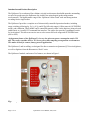
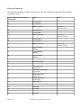
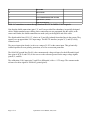
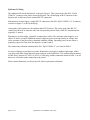
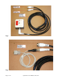
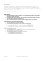
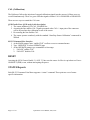
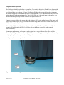
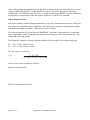
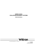
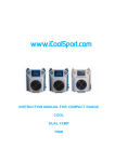
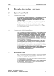
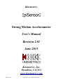
Kinemetrics
Strong Motion Accelerometer
User's Manual
Revision 2.01
June 2015
Kinemetrics, Inc.
Pasadena, CA USA
www.kinemetrics.com
Page 1 of 16
EpiSensor2 User's Manual, June, 2015
No User-Serviced Parts
The EpiSensor2 is a self-contained seismic accelerometer. There is no reason to open the sensor
package, or to modify the electronics or sensor elements contained within it. There are no
internal manual adjustments to make to, nor are there any user-serviced parts within the sensor.
Opening and/or modifying the sensor is unnecessary, and doing so will void the instrument's
warranty.
Electrical Safety Notice
As with all electrical instruments, potentially lethal potentials can be present on all metal surfaces,
including conductors within any cables. Proper grounding of these elements is important to
minimize these risks. The user of this product is responsible for its installation and operation in a
safe manner, and in accordance with all local requirements for electrical safety.
Page 2 of 16
EpiSensor2 User's Manual, June, 2015
Introduction and Product Description
The EpiSensor2 is an advanced force-balance, triaxial accelerometer that builds upon the outstanding
record of its predecessor, the EpiSensor (the world's first seismological-grade strong motion
accelerometer). The high dynamic range of the EpiSensor2 allows both weak and strong motion
recording from a single sensor.
The EpiSensor2 provides a complete set of electronically-controlled operational modes, including
range-switching (allowing 4g, 2g, 1g, 0.5g, and 0.25g full-scale ranges), Offset removal (AUTOZERO
mode), and calibration. These modes can be controlled remotely, either via the digitizer (using selected
enable lines) or via an RS-232 command line interface. The sensor also provides a pushbutton switch
for local control. This allows an on-site user to select sensor full-scale range and AUTOZERO state
(ON or OFF).
An important feature of the EpiSensor2 is its very low quiescent power consumption: under 350
mW. The sensor consumes 60% to 70% lower power than competing strong motion accelerometers.
This makes it ideal for remote, battery-powered applications.
The EpiSensor2, and its cabling, are designed for direct connection to Quanterra Q330-series digitizers,
as well as digitizers from the Kinemetrics “Rock” series.
The EpiSensor2 module, and some of its features, are shown in Figure 1.
Figure 1. EpiSensor2 module.
Page 3 of 16
EpiSensor2 User's Manual, June, 2015
Electrical Connections
The EpiSensor2 contains a Souriau connectoron its side. The connections supported by this receptacle
are shown in Table 1.
851-07C16-26P50-A7-44 Receptacle
Pin Designator
Signal
A
Z Acceleration +
B
Z Acceleration -
C
Shield Connection
D
Y Acceleration +
E
Y Acceleration -
F
Shield Connection
G
X Acceleration +
H
X Acceleration -
J
Shield Connection
K
Z Channel Range
Indicator
L
Y Channel Range
Indicator
M
X Channel Range
Indicator
N
ANALOG Ground
P
CAL Enable Line
(Logic Level)
R
AUTOZERO Enable Line
(Logic Level)
S
RESET Enable Line
(Logic Level)
T
RANGE Enable Line
(Logic Level)
U
Enable Return
V
CAL Input +
W
CAL Input -
X
RS-232 TX
Page 4 of 16
EpiSensor2 User's Manual, June, 2015
Notes
Connected to
ANALOG Ground
Connected to
ANALOG Ground
Connected to
ANALOG Ground
Y
RS-232 RX
Z
RS-232 GND
a
Power Bundle Shield/CASE Ground
b
Input Power + (9-36V)
c
Input Power Return
Table 1. Connections to sensor through Souriau 851-07C16-26P50-A7-44 receptacle.
Note that the shield connections (pins C, F, and J) are provided for redundancy, in specially-designed
cables. Within standard sensor cabling, these connections are not propagated into the cables, at the
sensor end. Rather, the shield connections are made (only) at the digitizer end of the cable.
The digital enable lines (P, R, S, T, relative to U) are fully-isolated from other lines in the system. They
operate over an approximate 2-9V input range. The RS-232 interface (on pins X, Y, and Z) is fully
isolated as well.
The power inputs (pins b and c) work over a range of 9-36V at the sensor input. This galvanicallyisolated input has reverse-polarity protection, as well as overcurrent protection.
The ANALOG ground line (Pin N) is the common mode voltage reference for the differential signal
lines (pins A-B, D-E, and G-H). It also serves as the reference ground for the range voltage signals
(pins K, L, and M).
The calibration (CAL) input (pins V and W) is differential, with a +/-15V range. The common mode
reference for these signals is ANALOG ground (pin N).
Page 5 of 16
EpiSensor2 User's Manual, June, 2015
EpiSensor2 Cabling
The standard cable for the EpiSensor2 is shown in Figure 2. This 6 meter long cable (PN: “Epi2.0
320001-6”) connects to the sensor and to the digitizer. The 10-shell plug in the Y-extension, at the
digitizer end, is dedicated for the isolated RS-232 connection.
Kinementrics can also supply a simple RS-232 connection cable (PN “Epi2.0 320002-1.5). It connects,
as shown in Figure 3, to the 10-shell plug.
Among other cable options are ones without the RS-232 takeout. This can be used when RS-232
control is not desired, or when the cable run is beyond the practical limit of RS-232 communications
(typically 15 meters).
Kinemetrics can also supply “pigtailed” (connectorless) cables. The maximum cable length is at or
about 125 meters, owing to limitations related to digitizer power sourcing (mainly its voltage) and
series resistance in the power lines contained within the cabling. Operating power for the sensor is
generally expected to come from the digitizer (via pins b and c).
The connections within the standard cable (PN: “Epi2.0 320001-6.”) are listed in Table 2.
For users wishing to create their own cables, Kinemetrics can supply a standard, right-angle, soldercup, plug (with cable clamp) that will connect directly to the EpiSensor2. The commercial part number
for this item is Souriau 851-08EC16-26S50-44. This plug, and the connection details in Table 1, are all
that users will need to make connection to the sensor.
Please contact Kinemetrics to discuss specific cable requirements and details.
Page 6 of 16
EpiSensor2 User's Manual, June, 2015
Figure 2. Sensor with standard cable.
Figure 3. Standard cable with RS-232 cable connected.
Page 7 of 16
EpiSensor2 User's Manual, June, 2015
Inbound
End:
Sensor
Connector
Outbound
End:
Recorder
Connector
851-08E16Conductors Signal
26S50-44, RA
Plug
851-06E1626P50-44
Plug
Conductors
A
Wire 1/Pair 1 Z Acceleration +
(SB): White
A
Wire 1/Pair 1 (SB):
White
B
Wire 2/Pair 1 Z Acceleration (SB): Black
B
Wire 2/Pair 1 (SB):
Black
C
NC
C
Signal Bundle Shield
Drain Wire
D
Wire 1/Pair 2 Y Acceleration +
(SB): White
D
Wire 1/Pair 2 (SB):
White
E
Wire 2/Pair 2 Y Acceleration (SB): Brown
E
Wire 2/Pair 2 (SB):
Brown
F
NC
F
Control Bundle
Shield
Drain Wire
G
Wire 1/Pair 3 X Acceleration +
(SB): White
G
Wire 1/Pair 3 (SB):
White
H
Wire 2/Pair 3 X Acceleration (SB): Red
H
Wire 2/Pair 3 (SB):
Red
J
NC
J
NC
K
Wire 1/Pair 5 Z Channel Range
(CB): White Indicator
K
Wire 1/Pair 5 (CB):
White
L
Wire 2/Pair 5 Y Channel Range
(CB): Yellow Indicator
L
Wire 2/Pair 5 (CB):
Yellow
M
Wire 1/Pair 6 X Channel Range
(CB): White Indicator
M
Wire 1/Pair 6 (CB):
White
NC; wire
floats
Wire 2/Pair 6
(CB): Green
NC; wire
floats
Wire 2/Pair 6 (CB):
Green
N
Wire 1/Pair 4 ANALOG Ground
(SB): White
N
Wire 1/Pair 4 (SB):
White
NC; wire
floats
Wire 2/Pair 4
(SB): Orange
NC; wire
floats
Wire 2/Pair 4 (SB):
Orange
P
Wire 1/Pair 7 CAL Enable Line
(CB): White (Logic Level)
P
Wire 1/Pair 7 (CB):
White
R
Wire 2/Pair 7 AUTOZERO Enable R
(CB): Blue
Line
(Logic Level)
Wire 2/Pair 7 (CB):
Blue
Page 8 of 16
Signal Bundle Shield
Control Bundle
Shield
Outbound
End:
RS-232
Connector
EpiSensor2 User's Manual, June, 2015
851-06E10- Conductors
98S50-44
Plug
S
Wire 1/Pair 8 RESET Enable Line
(CB): White (Logic Level)
S
Wire 1/Pair 8 (CB):
White
T
Wire 2/Pair 8 RANGE Enable Line T
(CB) :Violet (Logic Level)
Wire 2/Pair 8 (CB)
:Violet
U
Wire 1/Pair 9 Enable Return
(CB): White
U
Wire 1/Pair 9 (CB):
White
V
Wire 1/Pair
10 (CB):
Black
CAL Input +
V
Wire 1/Pair 10 (CB):
Black
W
Wire 2/Pair
10 (CB):
Brown
CAL Input -
W
Wire 2/Pair 10 (CB):
Brown
X
Wire 1/Pair
11 (CB):
Black
RS-232 TX
X
NC
A
Triad Red
Wire
Y
Wire 2/Pair RS-232 RX
11 (CB): Red
Y
NC
B
Triad Black
Wire
Z
Wire 2/Pair 9 RS-232 GND
(CB): Gray
Z
NC
C
Triad White
Wire
a
1 M to
Power Bundle
a
Power
Shield/CASE Ground
Bundle
Shield Drain
Wire
Power Bundle Shield
Drain Wire
b
Wire 1/Pair
12 (PB):
Black
Input Power +
(9-36V)
b
Wire 1/Pair 12 (PB):
Black
c
Wire 2/Pair
12 (PB):
Orange
Input Power Return
c
Wire 2/Pair 12 (PB):
Orange
D
Triad Shield
Drain Wire
E
NC
F
NC
Table 2. Connection details of standard 6 meter cable.
Page 9 of 16
EpiSensor2 User's Manual, June, 2015
Operational Control of the EpiSensor2
The sensor can be controlled in multiple ways: button pushing (local), digitizer enable lines (remote)
and RS-232 (local and/or remote). Using either of these, the operator can control the full-scale range,
and AUTOZERO state, of the sensor. Using the digitizer or RS-232 interfaces, the user can control a
complete calibration (CAL) capability. Using a dedicated digital line connected to the digitizer, the
operator can issue a RESET to the sensor that is similar to a Power-ON-RESET. Finally, the user can
use the RS-232 interface to communicate with the sensor to receive a variety of sensor-specific
information (serial numbers, scalar response values, etc.). The RS-232 command line menu is
discussed further below.
Full-Scale Ranges
The EpiSensor2 supports five digitally-selectable ranges (with nominal scale factors):
Range 5: +/-4g (5 V/g)
Range 4:+/-2g (10 V/g)
Range 3: +/-1g (20 V/g)
Range 2: +/-0.5g (40 V/g)
Range 1: +/-0.25g (80 V/g)
There are red LEDs that show the current range. This range is stored in non-volatile memory. The
sensor range will be maintained upon a power-on- reset (POR) event. There are three methods for
setting the range:
Button Pushing
1. Press the button once for about 1 second (0.2 to 2 second acceptable window). This will light
the LEDs and “enable” the system
2. Each subsequent button push changes the range by one step in a cyclical fashion. Wait about 5
seconds between subsequent pushes.
3. After 30 seconds of inactivity, the LEDs will shut off and the system will be disabled
Digitizer Enable Lines (Q330 used for this description)
1. The sensor monitors the Q330's Generic Enable line 3 (“AUX 2”).
2. A pulse-length encoding scheme is used to select the range
1. Asserting the line for between 4.5 and 5.5 seconds places the sensor range at +/-4g
2. Asserting the line for between 3.5 and 4.5 seconds places the sensor range at +/-2g
3. Asserting the line for between 2.5 and 3.5 seconds places the sensor range at +/-1g
4. Asserting the line for between 1.5 and 2.5 seconds places the sensor range at +/-0.5g
5. Asserting the line for between 0.5 and 1.5 seconds places the sensor range at +/-0.25g
RS-232 Command Line Interface
1. At the MAIN prompt, enter “enable12345” to allow access to command menus
2. Type “OPERATE” to select OPERATE page
3. At the OPERATE prompt, type command to select range:
1. “4g” for +/-4g
Page 10 of 16
EpiSensor2 User's Manual, June, 2015
2.
3.
4.
5.
“2g” for +/-2g
“1g” for +/-1g
“0.5g” for +/-0.5g
“0.25g” for +/-0.25g
Range Signaling
The EpiSensor2 feeds a range-dependent signal into the the low resolution mass position channels of
the Q330:
5V (50 counts) for +/-4g range
4V (50 counts) for +/-2g range
3V (50 counts) for +/-1g range
2V (50 counts) for +/-0.5g range
1V (50 counts) for +/-0.25g range
In addition, the Episensor2 outputs a coded range signal on to each of the channels' SIGNAL line:
5 pulses for +/-4g range
4 pulses for +/-2g range
3 pulses for +/-1g range
2 pulses for +/-0.5g range
1 pulse for +/-0.25g range
This is output at power-ON, following a RESET event, and following any range-setting activity.
Typical pulses, for 4g range, are shown in Figure 4.
Figure 4. Pulse-train range signal for +/-4 g range.
Page 11 of 16
EpiSensor2 User's Manual, June, 2015
AUTOZERO
The EpiSensor2 has an autozero capability that will remove DC-offsets from the signal, up to an
acceleration-equivalent limit of +/-100 mg. Autozero operates simultaneously on all three channels.
There are only two modes: ON and OFF. The current state is stored in non-volatile memory. The sensor
will enter the appropriate state after a POR event.
There are three ways to control the autozero state:
Button Pushing
1. Press the button once for about 1 second (0.2 to 2 second acceptable window). This will light
the LEDs and “enable” the system
2. Push and hold the button for between 5 and 10 seconds to toggle the AUTOZERO ON/OFF. A
green LED will be lit when AUTOZERO is ON
3. After 30 seconds of inactivity, the LEDs will shut off and the system will be disabled
Q330 Enable Lines (Q330 used for this description)
1. The sensor monitors Q330 Generic Enable line 1.
2. A pulse-length encoding scheme is used to set the AUTOZERO state:
1. Asserting the line for between 1 and 3 seconds turns AUTOZERO ON
2. Asserting the line for between 4 and 6 seconds turns AUTOZERO OFF
RS-232 Command Line Interface
1. At the MAIN prompt, enter “enable12345” to allow access to command menus
2. Type “OPERATE” to select OPERATE page
3. At the OPERATE prompt, type command to select range:
1. “AUTOZEROON” turns ON Autozero
2. “AUTOZEROOFF” turns OFF Autozero
Page 12 of 16
EpiSensor2 User's Manual, June, 2015
CAL (Calibration)
The EpiSensor2 allows the injection of external calibration signals into the sensors. All three axes are
excited simultaneously. There is a green LED that signals whether CAL is ENABLED or DISABLED.
There are two ways to control the CAL state.
Q330 Enable Lines (Q330 used for this description)
1. The sensor monitors Q330 CAL_ENABLE line
2. Asserting the line enables CAL. Signals presented at the CAL+/- input pins of the connector
will be injected into the calibration circuit of the sensor
3. De-asserting the line disables CAL
4. The sensor operates seamlessly with the standard “Start/Stop Sensor Calibration” commands in
Willard.
RS-232 Command Line Interface
1. At the MAIN prompt, enter “enable12345” to allow access to command menus
2. Type “OPERATE” to select OPERATE page
3. At the OPERATE prompt, type command to select range:
1. “CALON” enables CAL
2. “CALOFF” disables CAL
RESET
Asserting the Q330 Generic Enable 2 (“AUX 1”) line rests the sensor. It effect is equivalent to a PowerON-RESET (POR) event, without interrupting the power.
STATUS Reports
Each RS-232 Command Line Menu supports a “status” command. These print out a set of menuspecific information:
Page 13 of 16
EpiSensor2 User's Manual, June, 2015
Setup and Initial Operation
The EpiSensor2 should be placed on a firm surface. The sensitive directions (X and Y) are aligned with
the sides of the sensor. The sensor should be leveled using the threaded adjustment feet and the bubble
level. One of these feet is shown in Figure 5. Following leveling, the feet can be locked by tightening
the lock nut up against the bottom of the sensor (finger tight only!). The central bolt hole can be used to
anchor the sensor to the mounting surface. This can use bolts and a threaded insert in the surface, or a
threaded stud that passes up from the surface to be captured with a nut.
Connect the sensor cable to the sensor and to the digitizer (Q330-series or Rock-series). The sensor will
power-ON over the course of a few seconds. The current range, and current AUTOZERO status (ON or
OFF), will be signified by the LEDs.
Wait until the LED extinguishes (about 30 seconds). Pressing the LED once (for between 0.2 and 2
seconds) will re-illuminate the LED. It will also activate the button system for further control
(discussed below).
Upon power up, the sensor will output an analog signal on its range indicator lines. These will be
recorded by the digitizer. The use can verify the current range setting by monitoring these values, or by
analyzing the pulse-train sequence, shown in Figure 4.
At this point, the sensor is operational.
Figure 5. Details of leveling feet.
Page 14 of 16
EpiSensor2 User's Manual, June, 2015
Operational Details
Choice of Digitizer
The instantaneous dynamic range of the sensor is greater than any modern seismic digitizer,
particularly when operating on the 4g and 2g ranges. 26-bit digitizers (such as the Q330HR) are
preferred for utilizing the greatest part of this range. More conventional 24-bit digitizers also work
well, however, the self-noise of a properly installed sensor is well below that of the input noise of the
digitizer. Some digitizers provide integrated preamplifiers. While these are useful for investigation of
the exact levels of sensor self-noise, their use will greatly reduce the full-scale range of the sensor. This
effectively defeats the purpose of a “strong motion accelerometer”! Typically, the best system
performance will be achieved by use of a Q330HR (26-bit) digitizer, with its preamplifiers OFF.
Full-Scale Range Selection
Sensor dynamic range is typically highest on the highest full-scale range settings (+/-4g and +/-2g),
where the 1 Hz dynamic range is in excess of 160 dB. However, sensor self-noise typically drops with
range setting (although noise on 0.5g and 0.25 g ranges are practically identical). The choice of (peak)
full-scale range should ensure that there is near-zero chance of clipping due to maximal local
signals. Users should select ranges above the maximum expected signal.
AUTOZERO Mode
The AUTOZERO system records and corrects the sensor offsets in situ. This correction cancels fixed
mechanical offsets in the sensor element, as well as tilt-related offsets due to sensor mounting. It injects
a separate feedback current that is automatically generated to cancel the observed offset. AUTOZERO
is either OFF (standard mode), or ON. Any time that the sensor is RESET, or it experiences a PowerON-RESET, or the AUTOZERO is explicitly set via the various control interfaces, the sensor recalculates and corrects its offsets. When continuously powered, the sensor retains the same offset
removal current setting.
AUTOZERO requires higher quiescent power consumption (about 120 mW extra), and it increases
self-noise levels. Unless the user has special requirements (e.g., very low dynamic range digitizer
requiring the use of input preamplifiers), Kinemetrics recommends leaving the AUTOZERO in its
OFF state. Any modern digitizer, as well as many data analysis algorithms, are not affected by DCoffsets in the signals or in the digital data.
Calibration (CAL)
Calibration is seamlessly supported through the digitizer connection. This includes a digital control line
for connecting the (differential) calibration input signals to the sensor elements, and use of the voltage
sources provided by the digitizer. For the EpiSensor2 (with DC-320+Hz bandwidth), random noise is
an excellent calibration stimulus source.
Retention of Settings
The current full-scale range and AUTOZERO status (ON or OFF) is stored in EEPROM within the
Page 15 of 16
EpiSensor2 User's Manual, June, 2015
sensor. These settings are updated whenever the status is changed by the user (or the digitizer). Upon a
system POWER-ON-RESET, or simple RESET, the sensor is restored to the previous operating
configuration. The calibration status, however, is volatile. Following any RESET event, the calibration
mode must be re-entered using either the digitizer enable line, or an RS-232 command.
Sensor Response Values
Each sensor element is trimmed during manufacture, to provide a standard scalar response (Volts/g) on
each of the five (operating ranges). In addition, each sensor axis is trimmed to ensure that its response
bandwidth falls within a set range (-3 dB point at or above 320 Hz).
The scalar responsivity (G) is stored on the “RESPONSE” page that is described below. A command
query on this page (“status” command) will return the scalar response values for each element, at the
current full-scale range setting.
The Episensor2 frequency response can be described well by a simple set of conjugate pole pairs:
P1 = -700+/-1250j (radians/second)
P2 = -1340+/-3350j (radians/second)
The full response is defined as:
V (s)
=
G |P1|2 |P2|2
(s – P1)(s – P1*)(s – P2)(s - P2*)
where G is the scalar responsivity (Volts/m).
Input Power Rquirements
RS-232 Command Line Interface
Page 16 of 16
EpiSensor2 User's Manual, June, 2015