Transcript
DVS 204 Digital Video Scaler
Installation
DVS 204
100-240V
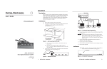
1. Turn off power to the DVS 204 and all other devices that will be connected. See the
application example on the right.
2. If the scaler is to be rack mounted, remove the self-adhesive rubber feet if they
have been attached. Refer to the DVS 204 User's Manual for rack mounting instructions.
3. Attach the scaler to the input and output devices. See connector diagrams below.
4. Plug the scaler, input devices, and output devices into a grounded AC source.
5. Turn on the input and output devices. Power up the scaler.
6. Use the LCD menu screens to configure the scaler. See Main Menu System below.
VIDEO
SDI input
Input 1: Composite video
Y
/VID
R-Y
R-Y
R
/R-Y
B-Y
/C
R-Y
3
Input 4: RGB pass-through/
RGBS/RGBcvS
NOTE
Use the Adjust horizontal
knob (
) and the Adjust
vertical knob ( ) to select
menu options.
G
/Y
B
/B-Y
V
S
REMOTE
RGB/R-Y,Y,B-Y
RS-232 Control
LCD Projector
VCR
Monitor
RGBS
G
/Y
B
/B-Y
R
/R-Y
V
S
H
G
/Y
B
/B-Y
R
/R-Y
V
S
H
15-pin HD output
OUTPUTS
G
/Y
B
/B-Y
V
S
RGB/R-Y,Y,B-Y
RGB
PASS - THRU/
RGBS/RGBcvS
OUTPUTS
H
4
RGsB
OUTPUTS
G
/Y
B
/B-Y
V
S
You can
connect both outputs
simultaneously to two
different displays. The
sync format is the
same for both outputs.
Component Video (R-Y, Y, B-Y)
Main Menu System
Power
on
2 sec.
EXTRON
DVS204D
2 sec.
852 x
480 @60
2 sec.
INPUT 1
CMPOSITE
2 sec.
NO
SIGNAL
2 sec.
* The No Signal default menu only occurs if
there is no signal present at the currently
selected input connector.
video for Input 1, composite/component/
S-video for Input 2, S-video for Input 3,
RGB pass-through/RGBS/RGBcvS for
Input 4. SDI can be assigned to any input.
MENU
INPUT
CONFIG
1
3
MENU
2 Output configuration – Select the
required output resolution and refresh
rate combination and whether Accu-RATE
Frame Lock™ is in effect. Select the
display's sync format: RGB, YUV, or
RGsB. Select positive or negative sync
polarity for the horizontal and vertical
sync.
2
4
MENU
Sync polarity cannot be specified for RGsB output.
lines from the top and bottom of the screen. Undesired noise or other
material, like closed captioning, can be removed. Adjust the blanking
from 0 to 127 lines.
4 Memory preset – The presets save Sizing and Centering information
for each input (up to 3 presets per input) except for the pass-through
inputs (RGB on Input 4). Select a preset number in the Save
submenu of the input, then press the NEXT button to save a preset.
To delete a saved preset in the Clear submenu of the input, select the
preset number, then press the NEXT button to clear the preset.
To recall an input's saved preset, select the input and press the input
button successive times to activate each saved preset for that input.
Each recalled preset will display the message "Input X Memory Y"
where "X" refers to the input (1 to 4) and "Y" refers to the preset
(1 to 3).
BLANKING
CONFIG
5
ADVANCED
CONFIG
MENU
MENU
OUTPUT
CONFIG
3 Blanking configuration – Top and bottom blanking will remove scan
NOTE
OUTPUTS
4
DVD Player
1 Input configuration – Select composite
NOTE
R
/R-Y
H
3
NOTE
R
/R-Y
2
S-VIDEO
Input 3: S-video
OUTPUTS
H
Y
/VID
2
2
INPUTS
RGB
PASS - THRU
RGBcS
S-VIDEO
2
BNC outputs
RGBHV
Y
/VID
Y
/VID
Laptop Computer
S-video (Y/C)
B-Y
/C
B-Y
/C
SDI
B-Y
/C
1
R-Y
Document Camera
Input 2: Composite/component/S-video
Component Video (R-Y, Y, B-Y)
VIDEO
SDI
1
Composite Video
0.3A
50/60 Hz
MEMORY
PRESET
6
MENU
EXIT
MENU
NEXT
MENU
5 Advanced configuration – The Detail feature controls output
sharpness. The adjustment ranges from 0 to 63.
The Filter mode reduces or eliminates aliasing and the resultant
"jail bar" effect. For digital displays, set the filter On to reduce high
frequency noise. For CRTs, set the filter Off.
Blue mode can be set On/Off. Setting this mode On will pass only sync
and blue signals to the display for setup purposes. The Blue mode will
be effective for RGB pass-through and YUV input signals YC input
signals will pass the Y, but not the C signal, so the output display will be
black-and-white only.
Autoswitch mode causes the highest numbered input that has a
signal present to be automatically selected. This mode is enabled by
setting Autoswitch to On. Setting this mode Off will disable Autoswitch.
Enhanced mode will enabled/disabled automatic gain control. A weak
signal level will be increased, and an excessive signal level will be
decreased. This mode can be set On or Off.
6 Exit – Return to the default menu cycle by pressing the NEXT button, or
return to the Input configuration menu by pressing the MENU button.
If no signal is present at the input, no preset can be saved
and the "No Signal" message will appear as part of the
default cycle.
Extron Electronics, USA Extron Electronics, Europe Extron Electronics, Asia Extron Electronics, Japan
www.extron.com
1230 South Lewis Street
Anaheim, CA 92805
USA
714.491.1500
Fax 714.491.1517
Beeldschermweg 6C
3821 AH Amersfoort
The Netherlands
+31.33.453.4040
Fax +31.33.453.4050
135 Joo Seng Road, #04-01
PM Industrial Building
Singapore 368363
+65.6383.4400
Fax +65.6383.4664
33-664-01
Daisan DMJ Building 6F
Rev. A
3-9-1 Kudan Minami
03 02
Chiyoda-ku, Tokyo 102-0074 Japan Printed in USA
+81.3.3511.7655
Fax +81.3.3511.7656