1
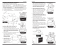
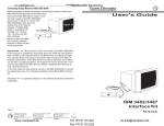
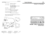
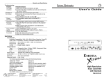
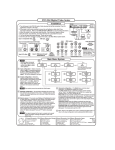
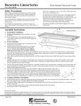
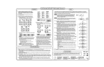
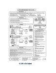
Installation Connecting Display Module to MBC-RGB Buffer Before connecting to power, proceed by connecting the display module to the MBC-RGB Buffer assembly as described below. Connect the MBC-IBM 3482-87 cable (1) from the logic module to the MBC-RGB Buffer (2) as shown in Figure 10. Connect the MBC-RGB Buffer cable (3) to the analog input of the selected interface. The MBC-RGB Buffer is compatible with the RGB 118, 118 Plus, 120, 108 Plus, and 202 Plus interfaces. Restore power and adjust the respective interface features to obtain the best visual presentation. User's Guide Special Note: The “Blue Enhance” control is provided on the MBC-RGB Buffer for the purpose of “brightening” the primary blue color within the color palette in order to attain a color display similar to the IBM terminal. Increasing the brightness (de-saturating) of the primary blue allows easy viewing of blue detail on projection applications. As the Blue Enhance control is advanced, some effect can be seen on magenta graphics. The magenta will tend to de-saturate. This is a normal side effect of the Blue Enhance feature. Adjust the Blue Enhance for best overall performance. At this time, adjust the blue enhance control on the MBC-RGB Buffer to achieve the desired blue color. This completes installation of the IBM 3482/87 Interface Kit. Infowindow II is a registered trademark of the International Business Machines Corporation. IBM 3482/3487 Interface Kit Page 3 P/N 70-019-01 EXTRON ELECTRONICS 1230 South Lewis Street Anaheim, CA 92805 (714) 491-1500 FAX (714) 491-1517 U.S.A. EXTRON ELECTRONICS, EUROPE Beeldschermweg 6C 3821 AH Amersfoort +31-33-453-4040 FAX +31-33-453-4050 The Netherlands EXTRON ELECTRONICS, ASIA 41B Kreta Ayer Road Singapore 089003 +65-226-0015 FAX +65-226-0019 Singapore 79-11 68-116-01 Rev. C Installation Installation of IBM 3482/3487 Interface Kit The IBM 3482/3487 Infowindow II kit consists of: 68-116-01 Installation Instructions 26-357-01 MBC-IBM 3482-87 Cable 880108* Adapter Assembly 26-364-01 MBC-RGB Buffer w/ Blue Enhance *NOTE: Please verify that 6 items below are included in the Adapter assembly. Qty, Part #, Part Description Qty, Part #, Part Description 1. 3, 990077, Mounting Plate Retainer 4. 4, 40-077-01, Thumbnut, 3/8”x 0.25”ht. 2. 2, 990076, Module Retainer 5. 3, 40-077-02, Thumbnut, 3/8”x 0.2”ht. 3. 1, 990075, Module Mounting Plate 6. 6, 40-005-01, #4 Hex Nut Installation 5. Place the module mounting plate on the display module as shown in Figure 5, lining it up so that the mounting hardware of the mounting plate retainer is fed through the proper holes. Tighten down with three 3/8” x 0.2 thumbnuts, (Figure 1, item 5). 6. Position the MBC Interface Cable so the cable exits toward the right side of the display unit (See Figure 6). Plug the MBC cable into the card edge receptacle in the display unit. The card edge receptacle normally receives the logic module. 7. Plug the logic module into the MBC connector of the interface cable. The plastic L-shaped retainers of the logic module should slide into the positioning holes of the retaining plate (See Figure 7). 8. Place a module retainer (Figure 1, item 2) over the logic module (one on each side) by sliding it over the mounting hardware as shown in Figure 8. Tighten down the module retainers with four 3/8” x 0.25 thumbnuts (Figure 1, item 4). Reattach the tilt/swivel stand to the bottom of the terminal as shown in Figure 2. Return the terminal to its normal operating position as shown in Figure 9. Installing the IBM 3482/3487 Infowindow II Kit 1. Disconnect all cables and the power cord. 2. Turn the display module upside down so that it sits on its top, with the screen facing you as shown in Figure 2. Pinch the blue latch within the tilt/swivel stand and pull up the edge of the stand from the display module. This completes the mechanical assembly of the Infowindow II kit. Connection of the MBC-Interface cable to the MBC-RGB Buffer is covered on Page 3. 3. Remove the logic module from the display module by pinching the plastic latch on the logic module toward the rear of the display - see Figure 3. Gently pull up and lift out the logic module. 4. Insert a mounting plate retainer (Item 1 in Figure 1) into each of the three logic module retainer holes in the display unit as shown in Figure 4. Page 1 Extron • IBM 3482/3487 Interface Kit • User’s Guide Extron • IBM 3482/3487 Interface Kit • User’s Guide Page 2