1
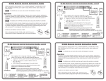
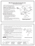
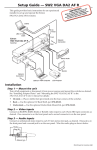
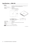
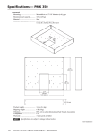
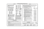
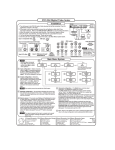
Nominal level .................................. 0.7 Vp-p for RGB
Minimum/maximum levels ......... Analog: 0.3 VDC to 1.5 VDC p-p with no
offset at unity gain
Impedance ........................................ 75 ohms
DC offset ........................................... ±5 mV maximum with input at 0 offset
Output resolution may vary depending on whether the P/2 DA1
is attached to the computer at startup, and on the type of
computer you are using.
User’s Guide
Sync
Input/output type ..........................
Input level ........................................
Output level .....................................
Input impedance .............................
Output impedance ..........................
Max. propagation delay .................
Max. rise/fall time ..........................
Polarity ..............................................
RGBHV, RGBS, RGsB, RsGsBs
2.0 V to 5.0 Vp-p
TTL: 5 Vp-p
510 ohms
75 ohms
18.8 ns
4 ns
Positive or negative
General
Power ................................................ 100 to 250 VAC, 4 watts, maximum, external,
attached
Temperature/humidity ................. Storage: -40 to +158 °F (-40 to +70 °C) /
10% to 90%, noncondensing
Operating: +32 to +122 °F (0 to +50 °C) /
10% to 90%, noncondensing
Rack mount ...................................... No
Enclosure type ................................. Plastic clamshell
Enclosure dimensions .................... 0.6" H x 1.3" W x 3.1" D
1.4 cm H x 3.3 cm W x 7.9 cm D
Product weight ................................ 0.5 lb (0.3 kg)
Shipping weight .............................. 1 lb (1 kg)
Vibration ........................................... ISTA 1A in carton
(International Safe Transit Association)
Listings .............................................. UL, CUL
Compliances .................................... CE
MTBF ................................................. 30,000 hours
Warranty ........................................... 3 years parts and labor
Part Number
P/2 DA1, 100 to 250V ..................... 60-319-02
All nominal levels are at ±10%.
P/2 DA1
Specifications are subject to change without notice.
VGA Line Driver
www.extron.com
Extron Electronics, USA
Extron Electronics, Europe
Extron Electronics, Asia
Extron Electronics, Japan
1230 South Lewis Street
Anaheim, CA 92805
USA
714.491.1500
Fax 714.491.1517
Beeldschermweg 6C
3821 AH Amersfoort
The Netherlands
+31.33.453.4040
Fax +31.33.453.4050
135 Joo Seng Road, #04-01
PM Industrial Building
Singapore 368363
+65.6383.4400
Fax +65.6383.4664
Kyodo Building
16 Ichibancho
Chiyoda-ku, Tokyo 102-0082 Japan
+81.3.3511.7655
Fax +81.3.3511.7656
© 2006 Extron Electronics. All rights reserved.
68-480-01 Rev. C
07 06
Installation
The Extron P/2 DA1 is a one input, one output VGA line driver. It
boosts the video signal between a laptop or desktop computer (input
device) and a monitor or large screen projector (output device).
Features
• The P/2 DA1 accepts and outputs VGA, XGA, SXGA, RsGsBs,
RGsB, RGBS, and RGBHV signals.
• The gain/peaking switch increases video signal voltages to
compensate for signal degradation caused by long cables.
1
15-pin HD input connector
2
Power LED — Lights to indicate that the P/2 DA1 is on.
3
Signal LED — Lights to indicate that an input signal is
being received.
4
Gain/peaking switch — Compensates for cable resistance
and capacitance.
Normal — Output is the same level as input.
Installation
Medium — 50% of the total gain is applied. Peaking is
applied.
To install the P/2 DA1, do the following:
1.
Turn off power to the input and output devices and unplug
their power cords.
2.
Connect the computer to the 15-pin HD male input
connector (see 1 in the “Operation” illustration below).
3.
Connect the output device to the 15-pin HD female output
connector (see 5 in the “Operation” illustration below).
4.
Reattach power cords, and apply power to the P/2 DA1
and to the input and output devices.
Many laptop computers have an external video port, but
they require special commands to output the video to that
connector. Also, many laptops’ screens shut off after the
port is activated. See the computer’s user’s guide for
details, or contact Extron for a list of laptop keyboard
commands.
Maximum — 100% of the total gain is applied. Peaking is
applied.
If the signal cable between the P/2 DA1 and the output
device is shorter than approximately 125 feet, and the gain
switch is set to Medium or Maximum, the image may be
overcompensated. If the edges of the image seem to exceed
their boundaries, or if thin lines and sharp edges look thick
and fuzzy, try changing the gain/peaking setting.
5
15-pin HD output connector
6
Power supply — 110–250 V desktop for international use.
Specifications
Video
Gain ................................................... 0 dB, 0.6 dB, 1.2 dB, selectable: when input is
0.7 Vp-p, output is 0.7 V, 0.75 V, 0.8 Vp-p
when switch is at normal, medium, and
maximum positions, respectively
Bandwidth ........................................ 300 MHz (-3 dB)
Note: ID bits will be passed through.
Operation
To computer
VGA IN
1
Video input
2
3
Number/signal type ......................
Connectors .......................................
Nominal level ..................................
Minimum/maximum levels .........
POWER
SIGNAL
GAIN/PEAKING
4
NORMAL
MEDIUM
MAXIMUM
6
5
1 VGA-UXGA RGBHV, RGBS, RGsB, RsGsBs
(1) 15-pin male
0.7 Vp-p for RGB
Analog: 0.3 VDC to 1.5 VDC p-p with no
offset at unity gain
Impedance ........................................ 75 ohms
Horizontal frequency ..................... 15 kHz to 135 kHz
Vertical frequency ........................... 30 Hz to 170 Hz
Video output
VGA OUT
To display device
2
P/2 DA1 Installation and Operation
Number/signal type ...................... 1 VGA-UXGA RGBHV, RGBS, RGsB, RsGsBs
Connectors ....................................... (1) 15-pin HD female
P/2 DA1 Operation and Specifications
3
Nominal level .................................. 0.7 Vp-p for RGB
Minimum/maximum levels ......... Analog: 0.3 VDC to 1.5 VDC p-p with no
offset at unity gain
Impedance ........................................ 75 ohms
DC offset ........................................... ±5 mV maximum with input at 0 offset
Output resolution may vary depending on whether the P/2 DA1
is attached to the computer at startup, and on the type of
computer you are using.
User’s Guide
Sync
Input/output type ..........................
Input level ........................................
Output level .....................................
Input impedance .............................
Output impedance ..........................
Max. propagation delay .................
Max. rise/fall time ..........................
Polarity ..............................................
RGBHV, RGBS, RGsB, RsGsBs
2.0 V to 5.0 Vp-p
TTL: 5 Vp-p
510 ohms
75 ohms
18.8 ns
4 ns
Positive or negative
General
Power ................................................ 100 to 250 VAC, 4 watts, maximum, external,
attached
Temperature/humidity ................. Storage: -40 to +158 °F (-40 to +70 °C) /
10% to 90%, noncondensing
Operating: +32 to +122 °F (0 to +50 °C) /
10% to 90%, noncondensing
Rack mount ...................................... No
Enclosure type ................................. Plastic clamshell
Enclosure dimensions .................... 0.6" H x 1.3" W x 3.1" D
1.4 cm H x 3.3 cm W x 7.9 cm D
Product weight ................................ 0.5 lb (0.3 kg)
Shipping weight .............................. 1 lb (1 kg)
Vibration ........................................... ISTA 1A in carton
(International Safe Transit Association)
Listings .............................................. UL, CUL
Compliances .................................... CE
MTBF ................................................. 30,000 hours
Warranty ........................................... 3 years parts and labor
Part Number
P/2 DA1, 100 to 250V ..................... 60-319-02
All nominal levels are at ±10%.
P/2 DA1
Specifications are subject to change without notice.
VGA Line Driver
www.extron.com
Extron Electronics, USA
Extron Electronics, Europe
Extron Electronics, Asia
Extron Electronics, Japan
1230 South Lewis Street
Anaheim, CA 92805
USA
714.491.1500
Fax 714.491.1517
Beeldschermweg 6C
3821 AH Amersfoort
The Netherlands
+31.33.453.4040
Fax +31.33.453.4050
135 Joo Seng Road, #04-01
PM Industrial Building
Singapore 368363
+65.6383.4400
Fax +65.6383.4664
Kyodo Building
16 Ichibancho
Chiyoda-ku, Tokyo 102-0082 Japan
+81.3.3511.7655
Fax +81.3.3511.7656
© 2006 Extron Electronics. All rights reserved.
68-480-01 Rev. C
07 06