1
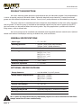
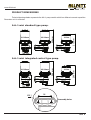
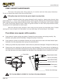
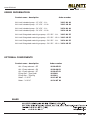
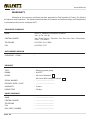
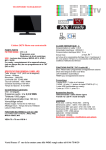
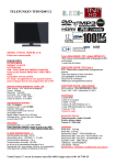
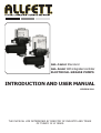
ALL-1mini Standard ALL-1mini With integrated controller ELECTRICAL GREASE PUMPS INTRODUCTION AND USER MANUAL VERSION 2.00 THE PHYSICAL LIFE DETERMINED BY MINISTRY OF INDUSTRY AND TRADE OF TURKEY IS 10 YEARS. www.allfett.net INTRODUCTION All industrial machinery, equipments and vehicles are working under abrasive operating conditions. The wear between frictional parts become the most highest level at these conditions. Machinery expose bad weather, dust, dirt, rain, snow and heavy weight in most cases. Consequently unwanted breakdowns occur and by that way productivity loss is inevitable. Using automatic lubrication system only increase your profitability. ALLFETT completely take over the work load spend on lubrication with a system which is bringing togather a pump, control unit, distributors, tubes and couplings. Lubrication work is done by ALLFETT centralized lubrication systems in efficient time of machinery or vehicle which is while operating. Lubrication is important for all frictional parts but using correct lubrication system and method only protect parts from wearing for a long time. Feeding lubrication points with correct dosage of lubricant at certain intervals while machinery is operating, provides lubricant film in place longer between parts. By ALLFETT lubrication systems life time of parts on your machinery and vehicles will be increased. ABOUT MANUFACTURER With over 25 years experience of manufacturing Centralized Lubrication Systems ALLFETT is able to provide a wide professional approach to select the correct Centralized Lubrication System for industry and heavy machinery. A highly accurate manufacturing process is involved in producing Centralized Lubrication Systems in order that systems meet the very tight quality procedures and state of the art processes are employed. ALLFETT is among the few companies whose products meet the exact technical and quality standards for a correct central lubrication. We present our high quality and advanced product design concept to our worldwide costumers through our strong brand. ALLFETT creates new opportunities and innovative solutions. As a result of the satisfaction of our customers with our good quality lubrication systems we are continuing in growing in the local and international market and became one of the successful companies in the field. WARNINGS Symbols and words shown below are meant to warn a particular risk to persons, material assets, or the environment. Please carefuly read this manual before installing. Failure to follow the instructions and safety precautions in this manual could result in serious injury or property damage. Caution Prohobition PAGE 1 Notice Electricity www.allfett.net CONTENTS INTRODUCTION PAGE 1 CONTENTS PAGE 2 PRODUCT DESCRIPTION AND GENERAL SPECIFICATIONS PAGE 3 PRODUCT DIMENSIONS PAGE 4 PRODUCT COMPONENTS PAGE 5 FUNCTION PAGE 6 PUMP ELEMENT DESCRIPTION PAGE 7 LUBRICANT INFORMATION PAGE 8 - 9 ELECTRICAL CONNECTION of ALL-1 Standard PAGE 10 ELECTRICAL CONNECTION of ALL-1 with Integrated contol PAGE 11 INTEGRATED CONTROL CARD DESCRIPTION PAGE 12 INTEGRATED CONTROL CARD PROGRAMMING INSTRUCTIONS PAGE 13 RULES TO COMPLY WHILE USING AND WARRANTY CONDITIONS PAGE 14 - 15 PUMP MAINTENANCE PAGE 16 PUMP ELEMENT MAINTENANCE PAGE 17 ORDER INFORMATION PAGE 18 WARRANTY PAGE 19 WARRANTY CONDITIONS PAGE 20 PAGE 2 www.allfett.net PRODUCT DESCRIPTION ALL-1mini electrical grease pumps are manufactured only for lubrication purpose. Pump displacement is varius to provide required lubrication needs. Optionally obtained pump element(s) creates pressurized grease out with different displacement volumes. 1 and up to 3 pump elements can be added on pump body. The pump reservoir is manufactured from transparent polycarbonate to allow user easily check the level of grease. In case the pump is installed so that operator cannot see the level of grease the ALLFETT low level sensor can be used to follow the level of grease. Top filling application is possible with different filling covers, with or without lock. ALL-1mini pumps can be controlled and monitored with integrated electronic control cards. Optional control card feature also displays warnings as broken fuse, fault and alarms. GENERAL SPECIFICATIONS Motor type : 12 - 24 V DC Working pressure : 400 bar. (with single pump element) 200 bar. (with 3 pump elements) : IP 54 Motor protection class Grease type : NLGI NLGI NLGI NLGI NLGI Working temperature : -25°C +80°C Reservoir capacities : 1 - 1,8 Liters 00 (-30°C) - (-10°C) 0 (-10°C) - (0°C) 1 (0°C) - (10°C) 2 (10°C) - (30°C) 3 (30°C +) OPTIONAL SPECIFICATIONS Pump elements : can be added 1 up to 3 pieces Pump element displacement : (Ø5) (Ø6) (Ø7) 1.5cm³ / minute 2.5cm³ / minute 3.5cm³ / minute Control card protection class : IP 65 Control card voltage : 10 - 30 V DC Working time period : Adjustable between 1 second to 99 minutes Waiting time period : Adjustable between 1 second to 99 hours Warnings : Broken fuse, Fault, Alarm ALL-1 pums are manufactured only lubrication purpose. It is not convenient to run these pumps more than 2 hours continuously. PAGE 3 www.allfett.net PRODUCT DIMENSIONS Technical drawings below represents the ALL-1 pump models which has different reservoir capacities. Dimension unit is milimeter. 1.8 Liters 1 Liter 273 mm 1.8 Liters 338 mm ALL-1 mini standard type pump. 164 mm 1.8 Liters 1 Liter 298 mm 1.8 Liters 364 mm ALL-1 mini integrated control type pump. 164 mm Ø9,1 94 Assembly holes PAGE 4 www.allfett.net PRODUCT COMPONENTS Technical drawings below represents the ALL-1mini pumps standard model and ALL-1mini Pump with integrated control model. Optional specifications described seperately. ALL-1 with integrated control ALL-1 Standard Exhaust Low level indicator socket (Optional) Agitator Low level indicator (Optional) Reservoir Grease filling filter (Optional) Pump element (Optional) Pump element positions Grease nipple Motor box Integrated control card (Optional) Motor box screws Electrical socket INTEGRATED CONTROL CARD COMPONENTS Integrated control card is optional. Not presented onto standard type ALL-1mini pumps. Cover screws Motor connection cables Fuse Control panel cover Control panel Assembly screws Electrical socket PAGE 5 www.allfett.net FUNCTIONAL DESCRIPTION Along with DC voltage electrical energy connected to ALL-1 pump filled with grease ; Electrical motor start to operate and agitator inside reservoir rotates clockwise. Spring returned pump element piston vacuums the lubricant inside reservoir. Rotational movement of the eccentric pushes pump element piston so that the lubricant vacoomed before is sended to pump element outlet with high pressure. Working pressure can be adjusted on security valve. The lubricant coming out from pump elements ; Displacement volume of the pump element can be connected to single lubrication point. However displacement volume can also be divided by progressive distributor to feed multiple lubrication points. Optional system control units ; Lubrication system and its components can be controlled and monitored with integrated electronic control cards. Digital sensores and also pressure switches where placed on system components send information to control card. Pump elements, distributors and control cards are offered optionally. While ordering a pump, other components have to be ordered separately according to their properties. Any maintenance on ALL-1 pumps under electrical voltage could lead to personal injury. Disconnect all electrical power before any maintenance . Any maintenance on ALL-1 pumps under high pressure could lead to personal injury. Discharge the system pressure before any maintenance . Unouthorized modifications to the units and the use of unouthorized spare parts and aids prohobited also disqualify the warranty. PAGE 6 www.allfett.net PUMP ELEMENT DESCRIPTION ALL-1mini grease pumps are available in several displacement volumes. These volumes can be created with pump elements which are optionally offered. 1 to 3 Pump elements can be applied onto ALL-1 mini pump body to take grease out. Even though single pump element can be used as outlet, multiple pump elements can be bridged as single outlet to get more displacement. Pump element is equiped with security relief valve to protect any damage may occure from high pressure. Lubrication system pressure is increasing when a lubrication point is blocked. Up to 450 bar. pressure, lubrication systems working pressure can be adjusted by security relief valve. Lubricant with over pressure will be out from exhoust hole. Pump elements are manufactured in 3 types according to diplacement amounts. These types can be described as its piston diameter ; with Ø5 mm piston, pump elements outlet displacement is 1.5cm³ / minute with Ø6 mm piston, pump elements outlet displacement is 2.5cm³ / minute with Ø7 mm piston, pump elements outlet displacement is 3.5cm³ / minute 42 mm Exhaust hole Security relief valve adjust screw Suction hole Piston Spring Outlet coupling Pump elements are offered optionally. When ordering a pump, pump elements have to be ordered separately according to displacement properties. PAGE 7 www.allfett.net LUBRICANT INFORMATION Lubricant specifications can be used with ALL-1 pumps are described below. Before filling reservoir please read carefuly these informations. Lubricant will be used in the system must certainly be clean and any foreign materials must not enter while filling. ALL-1 pumps are designed to use with in centralized lubrication systems only. It is not suitable to use ALL-1 pump for lubricant tranfering or circulation purpose. To remind that lubricants has content which may hazardous to environment. It is important that the county specific regulations and laws on the use and disposal of lubricants must be observed. Lubricant type - GREASE NLGI classes can be used with ALL-1 pumps are described below. Because of the flow characteristics of grease the NLGI class range should be changed at different weather conditions and also temperature differencies. for NLGI 00 grease recomended working temperature is between -30°C and -10°C for NLGI 0 grease recomended working temperature is between -10°C and 0°C for NLGI 1 grease recomended working temperature is between 0°C and 10°C for NLGI 2 grease recomended working temperature is between 10°C and 30°C for NLGI 3 grease recomended working temperature is 30°C and over Keep in mind that the substances of any lubricant are harmfull to environment. Their transport and storage require that special safety measures be taken. Only LITHIUM based and EP additive liquid greases must be used with in system. It is important that the grease will be used must resistant to high pressure. Make sure the liquid grease you are using is EP additive. Do not use rubber based grease in system. Do not use grease types with graphite in system. PAGE 8 www.allfett.net LUBRICATION INFORMATION Grease penetration properties is variable at different environment temperatures.The environmental temperature around lubrication lines must be concidered for choosing the correct grease. Grease properties should be appropriate that environmental temperatures. Changing NLGI classes at different temperatures is important to correct lubrication. If necessary, high temperature resistant lubricants should be used in some cases. It should not be forgotten that the grease penetration properties is variable at different environment temperatures. PRESSURE LOSE CHART Loosing pressure in lubrication lines depends on differend variables. The most important variables are pump displacement, environmental temperatures, tube diameter and NLGI class. Each variable must be considered for correct lubrication. The chart below represents the approximate pressure loose in tube which 1 meter long. Results are varies according to pump element displacement volume created by single or multiple pump elements. Result values are defined in bar. Single Ø6 mm pump element Tube diameter Ø6 x 1 (Ø6mm) Ø8 x 1 (Ø6mm) Ø10 x 1 (Ø8mm) Lubricant class 2,5 cm³ / minute 0°C NLGI 0 4,8 NLGI 1 8 NLGI 2 12,8 2,6 4,4 7 NLGI 0 NLGI 1 NLGI 2 1,32 0,72 0,42 0,24 3,9 2,2 1,2 0,7 0,4 6,5 3,52 1,92 1,12 0,64 10,4 2,7 4,5 7,2 NLGI 0 NLGI 1 (Ø21,25mm) NLGI 2 R 3/4 PAGE 9 10°C 20°C 30°C -10°C 1,4 2,4 3,8 0°C 0,78 0,48 7,8 4,2 1,3 0,8 13 7 1,28 20,8 11,2 2 2,1 3,5 5,6 NLGI 0 1,44 0,72 0,36 0,21 0,12 2,16 1,1 NLGI 1 2,4 1,2 0,6 0,35 0,2 3,6 1,8 NLGI 2 3,84 1,92 0,96 0,56 0,32 5,76 2,88 NLGI 0 0,96 NLGI 1 1,6 (Ø10mm) NLGI 2 2,56 NLGI 0 0,45 R 1/2 NLGI 1 0,75 (Ø15,75mm) NLGI 2 1,2 (Ø27mm) 7,5 cm³ / minute -10°C Ø12 x 1 R1 3 Ø6 mm pump elements NLGI 0 NLGI 1 NLGI 2 0,45 0,75 1,2 0,2 0,34 0,54 10°C 20°C 30°C 2,4 4 6,4 1,44 0,84 2,4 1,4 3,84 2,24 1,14 0,66 0,42 1,9 1,1 0,7 3 1,76 1,12 0,6 1 1,6 0,3 0,5 0,8 0,18 0,3 0,48 0,22 0,12 0,06 1,32 0,66 0,36 0,18 0,1 0,38 0,2 0,1 2,2 1,1 0,6 0,3 0,18 0,61 0,32 0,16 3,52 1,76 0,96 0,48 0,29 0,09 0,6 0,27 0,12 0,07 0,16 0,45 0,2 0,12 1 0,26 1,6 0,72 0,32 0,19 0,33 0,15 0,06 0,55 0,25 0,1 0,88 0,4 0,16 - - www.allfett.net ELECTRICAL CONNECTIONS of STANDARD TYPE PUMP Pumps have an electric driven motor. Electrical lines must be connected properly as described in schema below. Electrical socket is placed under motor cover. Transformer is necessary if there is no 24 V DC power source. Use minimum 5A current transformer. 12 - 24 V DC POWER SUPPLY Electrical socket (+) (-) 2 DC (-) 1 (+) Electrical socket Any maintenance on ALL-1 DC pumps under electrical voltage could lead to personal injury. Disconnect all electrical power before any maintenance . If ALL-1 DC pump will be used with ALLFETT EK-9 external control card, electrical lines must be connected properly as described in schema below. EK-9 external control card ALL-1 Pump Electrical socket EK-9 Control card socket 9 8 7 6 5 4 3 2 1 (-) 2 12 - 24 V DC POWER SUPPLY (+) DC (-) 1 (+) PAGE 10 www.allfett.net ELECTRICAL CONNECTIONS of INTEGRATED CONTROL CARD TYPE Pumps have an electric driven motor. Electrical lines must be connected properly as described in schema below. Electrical socket is placed under control card box shown below. S1 S3 S2 Integrated control card S1 - Standard electrical connection 12 - 24 V DC (-) 2 1 12 - 24 V DC (+) S2 - Warn leds connection (Optional) Green - LED 2 Red - LED 1 Yellow - LED S3 - Low Level indicator connection (Optional) Low level signal Low level (+) PAGE 11 2 1 Low level (-) connection in S1 socket gives high pressure signal while working time period. In waiting time period, same connection gives ADDITIONAL CYCLE button signal. www.allfett.net INTEGRATED CONTROL CARD DESCRIPTIONS CONTROL CARD PANEL WAIT. LUB. WARN. HOUR MINUTE SERVICE ADD. CYCLE SECOND PROGRAM DISPLAY WAIT. : Yellow LED (Waiting) LUB. : Green LED (Lubricating) WARN. : Red LED (Warning, Fault) HOUR : Shows unit of time. MINUTE : Shows unit of time. SECOND : Shows unit of time. PROGRAM DISPLAY : This led shows programming numbers. SERVICE : Using to start programming. ADDITIONAL CYCLE : Using to lubricate only one time except the programmed working time. And also using to change numbers while programming. CONTROL CARD ALARM LIST Alarms listed below are shown on PROGRAM DISPLAY. While alarm is occured PROGRAM DISPLAY will be indicating. Also while alarm is occured warn led will continýously flashing. A1 : Low level alarm This alarm is shown if pump out of grease. A2 : Pressure alarm This alarm is shown if adjusted pressure reached. A3 : Motor alarm This alarm is shown if motor cabels are broken or motor fault. A4 : Fuse broken This alarm is shown if fuse broken. PAGE 12 www.allfett.net INTEGRATED CONTROL CARD PROGRAMMING INSTRUCTIONS SERVICE and ADDITIONAL CYCLE buttons, where placed onto control card panel, are used for programming control card. 1. Press SERVICE Button twice to enter program mode. After entering program mode first digit on program display and green led start to flash. Working time period will be set first. 2. ADDITIONAL CYCLE button changes the numbers shown in flashing digit. Press Additional cycle button until desired number shown in flashing digit. Press SERVICE button to save digit. 3. After first digit saved, second digit starts to flash. ADDITIONAL CYCLE button changes the numbers shown in flashing digit. Press Additional cycle button until desired number shown in flashing digit. Press SERVICE button to save digit. 4. After second digit saved, time unit leds start to flash. ADDITIONAL CYCLE button changes the time units. Press Additional cycle button until desired time unit is flashing. Press SERVICE button to save time unit. Working time period is saved and setted. After this section waiting time period wil be set. 5. After seting working time unit, first digit on program display and yellow led start to flash. Waiting time period will be set. 6. ADDITIONAL CYCLE button changes the numbers shown in flashing digit. Press Additional cycle button until desired number shown in flashing digit. Press SERVICE button to save digit. 7. After first digit saved, second digit starts to flash. ADDITIONAL CYCLE button changes the numbers shown in flashing digit. Press Additional cycle button until desired number shown in flashing digit. Press SERVICE button to save digit. 8. After second digit saved, time unit leds start to flash. ADDITIONAL CYCLE button changes the time units. Press Additional cycle button until desired time unit is flashing. Press SERVICE button to save time unit. Waiting time period is saved and setted. Programming of the Integrated control card is now complated. Integrated control card starts the pump with working time period. While integrated control card is on, If ADDITIONAL CYCLE button pressed 2 seconds long remaining time period will be shown on program display. While programming, the time interval for pressing buttons must be in 20 seconds. If 20 seconds passes electronic control card exits from the program menu and operations done before is lost. In this case, card will start to operate with last succesfull programming values. In case of power breakdown while pump runs at waiting or working time periods, control card will remain its position before breakdown and resume after power comes. Power breakdown does not make any change on the structure of the previous program. PAGE 13 www.allfett.net RULES TO COMPLY WHILE USING AND WARRANTY CONDITIONS 1. Damages occur while additional transports after delivering the goods from ALLFETT to the customer DISQUALIFIES THE WARANTY. 2. Pumps are produced to lubrication purpose only and are not convenient to work more than 2 hours continuously. Working under maximum pressure more than 2 hours will harm the system. Damages occur from this reason DISQUALIFIES THE WARANTY. 3. Washing of the pump with pressured water causes damage. Any damage occur from this reason DISQUALIFIES THE WARANTY. 4. Pump reservoir is made of transparent material to see grease level. Painting any part of the pump is not recomended. Any painted parts DISQUALIFY THE WARANTY. 5. Pumps have an electric driven motor. Electrical lines must be connected properly as described in PAGE 10 - 11 and applied only by qualified and instructed personel. 6. All electrical connections and lines must be checked regularly for damage and to ensure that they are firmly in place. 7. Damages coming from voltage fluctuation, wrong electricity installation, connecting wrong voltage to product DISQUALIFIES THE WARANTY. 8. Keeping an uncovered cable(s) during system assembly may cause fatal damages where high voltage is transformed to low voltage. Lines must be connected properly to prevent personal injury and damage to property. 9. Transformer is necessary if there is no 24 V DC electrical source. Use minimum 5A current transformer. 10. Only proper NLGI class lubricants must be used with in system. NLGI class must be changed according to weather conditions. Use NLGI 0 for cold weather, increase the NLGI class up to 3 towards hot weathers. 11. Only LITHIUM based and EP additive lubricants must be used with in system. 12. Rubber based lubricant types must not be used in the system. Damages or faults occur from this reason DISQUALIFIES THE WARANTY. 13. Lubricant will be used in the system must certainly be clean and any foreign materials must not enter while filling. 14. Any foreign materials, dirt or small particules while filling lead to system units failing and possibly property damage to equipments. Damages or faults occur from this reason DISQUALIFIES THE WARANTY. 15. Pump must be filled from the grease nipple. If grease level is lower than the minimum level (as you can not see grease level) grease nipple must be used to prevent air entrance inside the pomp body. Lockable filling cover option can only be used after filling pump from grease nipple up to minimum level. PAGE 14 www.allfett.net RULES TO COMPLY WHILE USING AND WARRANTY CONDITIONS 16. If lockable filling cover will be used to fill pump, environment must be clean to avoid any foreign materials entering to reservoir. Any foreign materials, dirt or small particules while filling lead to system units failing and possibly property damage. Damages or faults occur from this reason DISQUALIFIES THE WARANTY. 17. If the pump works without lubricant, pump elements will send air to the points instead of grease. Because of that any points connected to pump will not get any lubricant. Damages on pump and on the system coming from that reason DISQUALIFIES THE WARANTY. 18. Using ALL-1 pumps with integrated control card models, high frequency wireless cominication devices 1 meter distance from the pump may couse malfunction. Damages or faults occur from this reason DISQUALIFIES THE WARANTY. 19. Integrated control card works between 10 to 30 Voltage. Although there is a protection against high voltage, control card may be broken if connected to high voltage power source. Damages or faults occur from this reason DISQUALIFIES THE WARANTY. 20. Disassembling or loosing any part while pump working is prohibited. Any damage coming from this reason DISQUALIFIES THE WARANTY. Also any personal injury occur from this reason ALLFETT does not accept responsibility. 21. Another goal of Centralized Lubrication Systems is to protect environment. So it is adviced to fill grease to the systems by mobile or hand pumps. 22. Unouthorized modifications to the units and the use of unouthorized spare parts and aids prohobited and DISQUALIFIES THE WARANTY. Only maintenance may apply descibed in PAGE 14 - 15. ALLFETT Technical Service must be informed to any other possible troubles and necessary procedures must be performed. 23. ALLFETT Mekanik ve Elektronik Sistemler SAN. TIC. LTD. STI and ALLFETT Pazarlama ve Dis Ticaret LTD. STI. does not accept responsibility for damages described in items above on equipments which ALLFETT systems are installed. QUALITY SYSTEM ISO 9001 BUREAU VERITAS Certification PAGE 15 This product is produced by ALLFETT Mekanik ve Elektronik Sistemler San. Tic. Ltd. Sti. company, which, is certificated by Bureau Veritas with certificate to compatible for ISO 9001:2008 standard and owner of the quality management system. www.allfett.net PUMP MAINTENANCE 1. IF PUMP NOT STARTS a. Electrical connections of the pump may be loosen or broken. Check the electrical cables and connections of the system according to schemas on page 9 and page 10. b. Connected electricity to pump may different then DC voltage. Connect the electricity 12 or 24 V DC which is marked on pump sticker. c. Connected electericity may be converted to DC voltage from AC voltage by a transformer. Transformer must be minimum 5A current. d. If pump has low level indicator ; Control unit (PLC or integrated control card) may give failure and stops the pump because of the grease inside pump decreased under minimum level. Fill the reservoir according to items 10, 11, 12, 13, 14, 15 and 16 in RULES TO COMPLY WHILE USING AND WARRANTY CONDITIONS. e. If ALLFETT control card is connected the system ; Electronic control card may be in waiting period. Wait until working time starts. If necessary control card pass to working period by pressing ADDITIONAL CYCLE button. 2. IF PUMP NOT SENDING GREASE a. Grease inside pump decreased under minimum level. Fill the reservoir according to items 10, 11, 12, 13, 14, 15 and 16 in RULES TO COMPLY WHILE USING AND WARRANTY CONDITIONS. b. Pump elements may take air due to work without grease ; Read and apply PUMP ELEMENT MAINTENANCE information on page 14. Unouthorized modifications to the units and the use of unouthorized spare parts and aids prohobited and disqualify the warranty. TECHNICAL SERVICE PAGE 16 www.allfett.net PUMP ELEMENT MAINTENANCE First use of the pump after filling reservoir, air mut be send out from pump element(s). To do this operation please read description below ; Filling the pump must be done by grease nipple on pump body. Remove connected tube from pump elements outlet coupling. Loose pump element from pump body for 2 - 3 turns. Start to operate pump. When grease coming from around pump element body, tighten again pump element body to pump. Pump should run contiuously untill grease without air is seen from pump element outlet. When the grease without air seen from pump element outlet, coupling must be tightened to outlet again With this process pump element is now ready to send grease to lubrication point. Grease coming out from end point of lubrication line may take long time according to line length. If problems may appear while operate ; a. Pump elements piston spring may broken. Remove the pump element and spring carefully. Pay attention spring does not fall into body. Change the spring if necessary. b. Pump elements piston may blocked. Remove the pump element and clean with diesel based liquid. Assemble it to the pump body after drying with pressurized air. c. Sealing ring inside the pump elements check-valve may weared or damaged. Change the sealing ring. d. Grease may seen coming out from the security valve discharge. This means there is a blockage in lubrication point or distributor connected this pump element. Blockage may cause the system to reach very high pressures and couse explode the lubrication lines. Blockage must be identified and fixed. Pump body Pump element outlet Security valve body Pump element body Grease suction hole Piston spring Piston Security valve discharge ALL-1 pump body is suitable for 1 and up to 6 pump elements. PAGE 17 www.allfett.net ORDER INFORMATION Product name - description Order number ALL-1mini standard pump - 12 V DC - 1 Lt. ALL-1mini standard pump - 12 V DC - 1.8 Lt. 20 12 01 A1 20 12 18 A1 ALL-1mini standard pump - 24 V DC - 1 Lt. ALL-1mini standard pump - 24 V DC - 1.8 Lt. 20 24 01 A1 20 24 18 A1 ALL-1mini Integrated control type pump - 12 V DC - 1 Lt. 20 12 01 EC ALL-1mini Integrated control type pump - 12 V DC - 1.8 Lt. 20 12 18 EC ALL-1mini Integrated control type pump - 24 V DC - 1 Lt. 20 24 01 EC ALL-1mini Integrated control type pump - 24 V DC - 1.8 Lt. 20 24 18 EC OPTIONAL COMPONENTS Product name - description ALL-1 Pump element - Ø5 ALL-1 Pump element - Ø6 ALL-1 Pump element - Ø7 Filling filter - Type Small Filling filter - Type Big Motor - 12 V DC Motor - 24 V DC Order number 10 00 05 02 10 00 06 02 10 00 07 02 10 0260 10 0261 10 12 MT 01 10 24 MT 01 SALES PAGE 18 www.allfett.net WARRANTY Utilisation of this warranty certificate has been permitted by The Republic of Turkey, The Ministry of Industrial and Commerce, The general Administration of Protection of Consumer Right and Competition, in accordance with the law numbered 4077 . PRODUCER COMPANY NAME : ALLFETT Mekanik ve Elektronik Sistemler San. ve Tic. Ltd. Þti. CENTRAL ADRESS : Yeni Eyup Bulvari, Topcular Cad. Set Ustu, No:1 DemirkapýRami / Ýstanbul TELEPHONE : 0212 501 32 01 (PBX) FAX : 0212 501 33 37 AUTHORISED PERSON SIGNATURE - STAMP : : PRODUCT TYPE : Electrical grease pump BRAND : ALLFETT MODEL : ALL-1mini Standard SERIAL NUMBER ALL-1mini With integrated control : ................................... DELIVERY DATE / PLACE : ................................... WARRANTY : 2 years REPAIR TIME : 30 days SALER COMPANY NAME : ................................... CENTRAL ADRESS : ................................... TELEPHONE : ................................... FAX : ................................... BILL DATE / NUMBER : ................................... PAGE 19 www.allfett.net WARRANTY CONDITIONS 1. 2. 3. 4. 5. 6. 7. The warranty period is two years from the date of delivery. The product including all its components is under the warranty of our company. In case of defects within the warranty period the period spent in repairing is added to the warranty period. The repairing period is maximum 30 days. This period starts from the date of delivery of the product to the services centers or to the seller, the agency the representative, the importer or the manufacturer of the product respectively, in case there are service centers. In case the product has material, workmanship or manufacturing defects, the product will be repaired free of charge and expenses of any sort including labor, the value of the parts replaced or any our charges. The product will be replaced free of charge; - If the product permanently disfunctions due to repeating the same defect more than four times within the warranty period - If the maximum period for repairing is exceeded. - If it is determined that the defect cannot be repaired by report written by the service, or in the absence of service centers, by the seller, agency, representative, importer or manufacturer of the product respectively. The present warranty does not cover damages resulting from importer handling by deviating from the instructions in the manual. General administration of protection of consumer rights and competition in the ministry of industry and commorce may be applied for problems concerning the warranty certificate. PAGE 20 www.allfett.net DANGEROUS OR HARMFUL CONDITIONS TO ENVIRONMENTAL AND HUMAN HEALTH DURING USE All ALLFETT systems are producing according to relevant provisions of security regulations. There is no risk for environmental and human health during use. TRANSPORT AND STORAGE There are no restrictions on transportation by land, air and sea. In general, products should be stored in a dry and dust-free environment. The storage temperatures are between -10°C and +40°C. All products are packed with paper based support matarial to reduce damage. Upon receiving the package please check the items for possible damage. PAGE 21 www.allfett.net NOTES PAGE 22