1
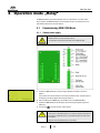
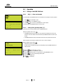
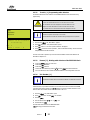
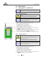
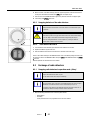
WGW 3300 Basic
3.4.2
Status of the WGW 3300 Basic
3.4.2.1
Show Status-menu
The following information is indicated in the status-menu of the WGW 3300 Basic:
A l :
– – –
F
:
– – –
R F :
– – –
a mo u n t :
X
Position
Indication
Meaning
Row 1
Al (Alarm)
Existing radio detector alarms
The radio address of the detector in alarm condition will be indicated
Row 2
F (Fault)
Existing radio detector fault s
The radio address of the detector in fault condition will be indicated
Row 3
RF (Radio Fault)
Existing radio faults
The radio address of the detector with radio faults will be indicated
Row 4
amount
Amount of radio detectors programmed to the WGW 3300 Basic
Status
(XXXXXXXX)
Condition in clear text; 8 digits from the right
X X X X X X X X
8-Bit Status
X
X
X
X
X
X
X
X
|
|
|
|
|
|
|
|
H
G
F
E
D
C
B
A
The following messages are indicated:
„24V fault“: Fault in the 24V Power supply
„Batt low“: Battery power of the WGW-emergency power supply low
Position
Meaning
Value A
Internal error of the WGW 3300 Basic or battery currency of a radio detector to low
Value B
Alteration of status of a radio detector
Value C
New pre-alarm radio detector
Value D
New fault radio detector
Value E
New alarm radio detector
Value F
Collective declaration pre-alarm radio detector
Value G
Collective declaration fault radio detector
Value H
Collective declaration fire alarm radio detector
3.5
Excavator design of radio detector
The following radio detector can be integrated in to the radio detection system WGW 3300 Basic.
3.5.1
Radio detector WL 3200 O
Optical radio smoke detector
1 Detector base
2 Detector dome with integrated battery case
3 Light conductor pole (Test button)
The test button of the detector is this light conductor pole which sticks out of the dome.
This pole indicates the red or yellow LED of the radio detector.
Version 2.1
13