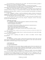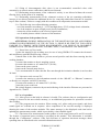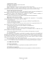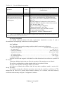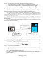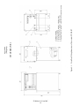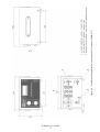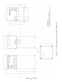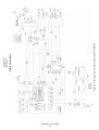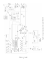
1
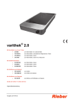
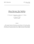
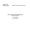
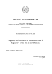
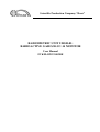
Scientific Production Company “Doza” RADIOMETRIC UNIT UDGB-01: RADIOACTIVE GASES/H-3/C-14 MONITOR User Manual FVKM.412123.003RE Cont ent 1 Description and operation of the product ………………………...………… 1.1 Product functionality …………………………………….…………...… 1.2 Technical characteristics …………………………………………......… 1.3 Configuration ………………………………………….………..……… 1.4 Design and operation …………....………………………………...…… 1.5 Marking and sealing …………………...………………………...…...… 1.6 Packing ………………………………………………………….........… 2 Intended use …………………………………………………………..….… 2.1 Operational limitations ……………………………………………….… 2.2 Preparation of the product for use ..…………………………………….. 2.3 Use of a product …….….….…………………………………………… 2.4 Adjustment ……………………………………………………………... 3 Maintenance …………………………………………………………...…… 3.1 General notes ………………………………………………………...… 3.2 Safety precautions ……………………………………………....……… 3.3 Maintenance routine ……………………………………………....….… 4 Calibration routine ………………………….……………………………… 4.1 General requirements …………………………………………….…..… 4.2 Preliminary arrangements …………………………….……….......…… 4.3 Safety precautions …………………………………………….…...…… 4.4 Conditions ………………………………………………………....…… 4.5 Procedure ………………………….…………………..……………..… 5 Routine repairs …………………………………………….……………….. 6 Storage ………………………………………………………….………..… 7 Transportation …………………………………………………...…………. 8 Disposal ………………………………………………………………..…… 3 3 3 5 6 7 7 7 7 8 8 9 9 9 9 10 10 10 10 11 11 12 14 14 14 15 Appendix A Outline drawing ……………..…………………...………….….... Appendix B Wiring diagram ……………………...……………………..…….. Appendix С Connection layout …………………………....…………….….…. Appendix D Soldering of the interface Ethernet ……………………………..... Appendix E Coefficients of sensitivity to beta radiation of certain gases ……... Appendix F List of parameters accessible for displaying and editing using the “Configurator” Software …………………………………………….. Appendix G Reference data for calibration …………………….…….....….…. 16 19 22 27 26 FVKM.412123.003RE 2 28 31 This document combines user manual and passport of the device; it contains information on design, principle of operation, characteristics of the product and instructions essential for correct and safe use of this product (intended use, maintenance, servicing, storage and transportation), as well as information regarding the utilization of the product. 1 DESCRIPTION AND OPERATION OF THE PRODUCT 1.1 Product functionality Radiometric unit UDGB-01: radioactive gases/H-3/C-14 monitor (hereinafter – monitors) is intended for the continuous measurement of volumetric activity of beta emitting-gases (argon, krypton, xenon) and gases with content of tritium and carbon-14 (hereinafter – beta-emitting gases) in controlled areas. Monitors are used at nuclear power plants and nuclear facilities. In case of using the monitors for measurement of volumetric activity of beta-emitting gases in the air containing radioiodine isotopes, additional purification of the gas mixture is necessary by means of filters or sorbent traps. The monitors is able to transfer data to communication channels and provides access to the processed information via communication lines based on Ethernet IEEE 802.3 interface (TCP/IP communications protocol) or RS-485 interface (ModBUS communication protocol), RS-232 and can be operated both on off-line mode and as a component of radiation monitoring systems, complexes and installations. The monitors can be mounted in stationary position in the gas sampling system or used as a portable measurement device. Three modifications of the monitors are available, namely UDGB-01T FVKM.412123.003, UDGB-01T1 FVKM.412123.004, UDGB-01T2 FVKM.412123.005, which differ from each other by their structural features and functional capabilities as described in section 1.4. 1.2 Technical characteristics 1.2.1 Energy range of detected beta emitting gases ……………….…..………… 5 to 3000 keV. 1.2.2 Measurement range of volumetric activity - beta-emitting nuclides in gases (except tritium): 1) UDGB-01T, UDGB-01T1...…….…….……...…….…...……….. 1.0·104 to 5.0109 Bq/m3, 2) UDGB-01T2 ...…….…..…….…..…….……...…...…..……….. 1.0·109 to 5.01014 Bq/m3 ; - tritium: 1) UDGB-01T, UDGB-01T1 ...…….…….……...…..….………….. 5.0·104 to 5.0109 Bq/m3, 2) UDGB-01T2 ...…….…..…….…..…….…….....…...………….. 5.0·109 to 5.01014 Bq/m3 ; 1.2.3 Limits of allowable basic relative measurement error of beta-emitting nuclides volumetric activity …………………………………...…….……………...…………..…………………...... ±20 %. 1.2.4 Intrinsic background of the monitor does not exceed .……….……………… 4·103 Bq/m3. 1.2.5 Relative sensitivity of the monitor to beta radiation of selected radionuclides is characterized by factor ξ shown in the Table 1.1. ξ is the ratio of sensitivity to beta radiation of specific radionuclide to the sensitivity to beta radiation of 85Kr. FVKM.412123.003RE 3 Table 1.1 - Relative sensitivity of the monitor to beta radiation of selected radionuclides Modification UDGB-01T, UDGB-01T1 UDGB-01T2 Factor ξ 3 133 H 0.104 1.04·10 14 Xe 1.337 -3 1.34·10 C 0.682 -2 6.82·10-3 1.2.6 The monitors can be operated with pump unit BN-01 FVKM.064424.002 or other external sampling device providing flow rate through the ionization chamber not less than 20 l/min. 1.2.7 Warm-up time ….………………………...….…...……………………………….. 10 min. 1.2.8 Continuous operation ….………………………...….……….………………….. 24 hours. 1.2.9 Instability during 24 hours of continuous operation ..……………...……………… 10 %. 1.2.10 Power supply of the monitors is performed from single-phase electrical line with AC 1 voltage 22022 33 V, frequency 50 1 Hz. 1.2.11 Power consumption ………………..…….…..…………..….…………..….……. 30 VA. 1.2.12 The monitor provides: - generation of self-testing codes; - current measurement data displaying on the liquid-crystal display (LCD) and transfer of the data to external information network based on interfaces RS-232, Ethernet IEEE 802.3 (interface protocol TCP/IP) or RS-485 (interface protocol ModBUS, RTU); - closing/opening of “dry contact” in case of exceeding the threshold. 1.2.13 The monitor maintains operability under conditions of the background gamma radiation with ambient dose equivalent rate (hereinafter referred to as AEDR) as follows: - for modifications UDGB-01T, UDGB-01T1 ….……..………….. not more than 0.2 mSv·h-1; - for modification UDGB-01T2 …….…………….………..………... not more than 1 mSv·h-1. 1.2.14 Operating conditions: - operating temperature range ……………………..……………………… minus 10 to +50 °C; - relative humidity …………..………………..……..……..……………..…… 98 % at +35 C; - atmospheric pressure ……………………………..…….……………….… 84.0 to 106.7 kPa; - content of the corrosive agents in the ambient air corresponds to the values in table 1.2. Table 1.2 Type of atmosphere Designation Description I Relatively clean II Industrial III Maritime Content of the corrosive agents Sulfur dioxide gas no more than 20 mg/(m2·day) (not more than 0.025 mg/m3); Chlorides not more than 0.3 mg/(m2·day) Sulfur dioxide gas no more than 20 to 250 mg/(m2·day) (not more than 0.025 to 0.31 mg/m3); Chlorides - not more than 0.3 mg/(m2·day) Sulfur dioxide gas not more than 20 mg/(m2·day) (not more than 0.025 mg/m3); Chlorides – 30 to 300 mg/(m2·day). Limits of complementary measurement error of volumetric activity within the range of operating conditions: - due to deviation of the ambient air temperature from normal value ………..………..… ±10 %; - under increased relative humidity up to 98% at +35C ……………………..….…….. ±10 %. FVKM.412123.003RE 4 1.2.15 Monitors withstand sinusoidal vibrations in the frequency range from 5 to 35 Hz with displacement amplitude 0.35 mm. Limits of complementary measurement error under conditions with vibration ……..…... 5 %. 1.2.16 Monitors are stable against seismic impacts with magnitude 6 according to the MSK-64 scale, being installed on the building structures of the industrial site 10 m relative to the grade level. After the seismic impact with the above mentioned parameters monitors are operable within the limits stated in sections 1.2.3, 1.2.12 during the whole life cycle under specified operation conditions. 1.2.17 Degree of protection provided by casings against ingress of solid items and water - IP23. 1.2.18 Monitors withstand the electromagnetic interference of the 3 grade according to IEC 1000-4-8-93, IEC 1000-4-9-93, IEC 61000-4-2-95, IEC 61000-4-3:2006, IEC 61000-4-4:2004, IEC 61000-4-5-95, IEC 61000-4-6-96, IEC 61000-4-11:2004, IEC 61000-4-12-95, IEC 61000-4-13:2002, IEC 61000-4-14-99, IEC 61000-4-28-99. 1.2.19 Monitors comply with the standards for emission set forth by IEC 61000-3-2:2005, IEC 61000-3-3:2008 and CISPR 22:2006 for class A equipment. 1.2.20 By its protection against electric shock monitors comply with the IEC 61010-1:2001. 1.2.21 Monitors are fire-safe products with fire probability of no more than 10-6 year-1. 1.2.22 Monitors withstand the exposure to decontaminating solutions: 1) boric acid (H3BO3) – 16 g, sodium thiosulfate (Na2S2O3·5H2O) – 10 g, distilled water – up to 1 liter; 2) trisodium phosphate or sodium hexametaphosphate (any detergent) – 10 - 20 g/l water solution; 3) 5 % citric acid solution in rectified alcohol – for connectors and contacts. 1.2.23 Weight, not more than: - UDGB-01T ………………………...………………….………….…..……………...… 30 kg; - UDGB-01T1 ………………………………………………..…...………...…………. 12,5 kg; - UDGB-01T2 ………………………………………………...…..……….………....….. 27 kg. 1.2.24 Overall dimensions, not more than: - UDGB-01T, UDGB-01T2 …………….……………..……….....……..… 381343716 mm, - UDGB-01T1: electronic unit …………………………...….…….…...…. 269315173 mm, detector unit BDGB-02P ...………..….…….….………… 262600240 mm. 1.2.25 Mean time before failure …………………….………………. not less than 10000 hours. 1.2.26 Mean life time ………………………………….….…………..…. not less than 10 years. 1.3 Configuration 1.3.1 The monitor is comprised of the following main parts: - an electronic unit and a chamber block with a built-in detector unit BDGB-02P for modification UDGB-01T and a detector unit BDGB-02P6 for modification UDGB-01T2, combined in one construct; - an electronic unit and external detector unit BDBG-02P (flow-through chamber) or BDGB-02P (diffusion chamber) for modification UDGB-01T1. Outline drawing are presented in the Appendix A. Spare cartridge is included in the spare parts and accessories kit delivered with the monitor. Software “Configurator” (hereinafter - “Configurator” software) is intended for testing and adjusting and calibration of the monitor using personal computer. Connecting cable is used for connection to PC; it is connected to the RS-232 socket on the electronic unit. FVKM.412123.003RE 5 1.4 Design and operation 1.4.1 The electronic unit provides the following: - data exchange with detector units; - indication of air pumping through the ionization chamber of the detector unit; - calculation of measured value of volumetric activity; - displaying of the measured value on the liquid-crystal display (LCD); - accumulation of measurement results archive; - transfer of measured values and status of the monitor to external information network; - audible and light indication when the measured value exceeds specified threshold. The electronic unit can transmit control signals to the “dry contact” and signaling device (SD) or similar device. The electronic unit is connected to AC mains using the power cord. The chamber block is designed for placement of the detector unit. The detector unit BDGB-02P is a flow-through ionization chamber with volume 10 liters, equipped with an electrometer and intended for measuring the ionization current due to ionization of the air inside the chamber by beta and gamma radiation of radioactive gases and by external background radiation. For ensuring stable operation of the chamber the electrometer is placed in the airtight casing and provided with silica gel cartridge. The cartridge (water vapor absorber) is intended for elimination of biasing current increase under conditions of increased humidity. The detector unit BDGB-02P6 is a flow-through ionization chamber with volume 100 cm3, equipped with an electrometer and intended for measuring the ionization current due to ionization of the air inside the chamber by beta and gamma radiation of radioactive gases and by external background radiation. The filter holder is used for filter installation in order to prevent aerosols and dust ingress into the working volume of the ionization chamber. Removing of aerosols by filtration from the inlet air is a necessary condition for maintaining operability of the monitor. The filter holder is delivered by the customer's request if the sampling point where the monitor will be used is not equipped with aerosol filtering device. The holder is not intended for accommodation of filters – absorbers of radioiodine, required for additional purification of the gas mixture from radioiodine isotopes. Filters – absorbers of radioiodine sorption traps and not included in the delivery kit of the monitor. 1.4.2 When external pumping is used then the air (cleaned from aerosols and, if necessary, from radioiodine) enters into the ionization chamber through the inlet connecting pipe after passing through the flow rate meter. The particles emitted by radioactive gases ionize the medium (air inside the chamber); it results in the current flow in the ionization chamber. The electrometer measures the current and transmits the data to the electronic unit, which process these data, calculates the activity concentration and transfers the calculated value to the information network and to the LCD. The flow rate meter is designed for the monitoring of air circulation through the ionization chamber. The threshold of the flow rate meter is set to 10 l/min. If the flow rate decreases below value, the electronic unit generates a failure signal “pumping failure”. This signal does not affect the results of measurement and is meant to inform an operator about the sampling system malfunction. 1.4.3 The electronic unit compares the received data with the threshold settings specified by the user during the device setup. In case the first threshold is exceeded an indication is triggered in the form of a yellow light signal and an audible signal, if the second threshold is exceeded the indication is a red light signal and an audible signal. The audible signal can be switched off by means of push button on the electronic unit. Alarm signals are duplicated by the signaling device if it is connected. FVKM.412123.003RE 6 If an external device is connected to the “dry contact”, the electronic unit makes it possible to switch this device on or off after exceeding the threshold. The connection layout to the “dry contact” is provided in Appendix В and Appendix C. 1.4.4 Each measurement result of the monitor is a value of volumetric activity of beta-emitting radionuclides in the monitored gas, calculated with the use of sensitivity to 85Kr. Taking into account the monitor’s energy dependence of sensitivity when determining the volumetric activity of real gas, it is necessary to choose certain gas with spectrum similar to the monitored one and, using relative sensitivity ξ, correct the measured result manually, by dividing the measured value by ξ. If the “Configurator” software is used for adjusting the monitor, all that is necessary for obtaining the volumetric activity of the monitored gas is to write the numerical value of sensitivity (indicated in the Appendix E) into the monitor’s memory. 1.4.5 The measured values are recorded into the non-volatile memory thus forming the archive of measurements which can be read out, if necessary, using the “Configurator” software. The memory can store up to 3000 measurements. 1.5 Marking and sealing 1.5.1 A nameplate with the following information is attached to the monitor housing: - trademark and name of the manufacturer; - reference designation of the monitor; - works number of the monitor according to the manufacturer numeration system; - sign of approval of the measurement instrument; - voltage, current and frequency of the AC power supply; - degree of ingress protection against solid items and water provided by casings; - made in Russia. Not e – The works number is marked on the control panel, all other monitor are marked with continuous serial numbers of the manufacturer. 1.5.2 Method of marking and place where it is made on the monitor and its parts shall comply with the design documentation. 1.5.3 All devices comprising the monitor are sealed in accordance with the design documentation. 1.6 Packing 1.6.1 The monitor’s package complies with the design documentation and provides protection against ingress of atmospheric precipitations and aerosols, splashes of water, dust, sand, solar ultraviolet radiation and limits the ingress of water vapour and gases. 2 INTENDED USE 2.1 Operational limitations 2.1.1 The monitors can be operated with gas sampling systems where the suction does not exceed 20 kPa. Maximum allowable pressure differential during blowings is 10 kPa. If blowings are carried out under pressure exceeding 10 kPa, cutoff of the monitor should be provided by means of the stop valve and blowing of the air line through the bypass. 2.1.2 For ensuring correct measurements it is necessary to include in the project damping means necessary during switching the sampling on/off, opening and closing of valves. It is necessary to install between the sampling (pumping) device and the monitor a receiver, a diaphragm, a filter, etc. to smooth the pressure pulsations during operation of sliding vane rotary and forevacuum pumps. Minimum volume of the receiver is 1/5 of the air volume pumped during 1 minute. FVKM.412123.003RE 7 2.1.3 Using of electromagnetic disk valves is not recommended; controlled valves with actuation by an electric motor with reducer shall be used instead. 2.1.4 Performing measurements of the volumetric activity is not allowed without the aerosol filtering device at the point of air sampling. 2.1.5 Performing measurements of the volumetric activity of the air containing radioiodine isotopes is not allowed without the additional device for removing radioiodine from the air (sorption trap or filter-sorbent). Failure to comply with this condition will compromise measurement results. 2.1.6 The following is not allowed during operation: - use of the monitors at medium (6 – 35 kV) and high (above 35 kV) voltage electric substation; - use of the monitors as parts of high power electric installations; - connection of the monitors to the circuit of signal earth; - use of mobile phones within 10 meters of the monitors. 2.2 Preparation of the product for use ATTENTION! DURING PREPARATION OF THE MONITOR FOR USE AND DURING OPERATION REQUIREMENTS OF THE SECTION 2.1 SHOULD BE STRICTLY FOLLOWED. FAILURE TO COMPLY WITH THESE REQUIREMENTS CAN RESULT IN INCORRECT OPERATION OF THE MONITOR AND, IN SOME CASES, CAN DAMAGE THE MONITOR. 2.2.1 Stand alone (off line) mode: 1) place the monitor to the working area (in case of using UDGB-01T1 connect the electronic unit and detector unit BDGB-02P using a cable); 2) install filter in the filter holder to prevent aerosol particles and dust from entering into the working chamber; 3) connect the monitor to the air sampling system; 4) connect the monitor to AC mains 220 V (50 Hz); 5) turn on the power switch; 6) turn on the external pump device; 7) it is recommended to ensure that the flow rate through the ionization chamber is not less than 20 l/min. 2.2.2 Operation with external PC: 1) connect the monitor to the information network via the “RS-485” or “Ethernet” connector or directly to a computer via RS-232 interface; 2) connect the monitor to AC mains 220 V (50 Hz); 3) turn the power switch on. The wiring diagram, connection layout and soldering of the interface Ethernet are presented in Appendixes B, C and D. 2.3 Use of a product 2.3.1 After power-on the built-in software is loaded. The software data set (configuration and settings) is located in the non-volatile memory, so no additional preparation for operation is needed after loading. 2.3.2 The program tests the monitor. When testing, red, yellow and green signals, and short sound signal are switched on in sequence. After completion of the test the message is displayed showing the status of the monitor modules. The status message is also displayed each time before updating the measurement results, which is preceded by a short audible signal. 2.3.3 The interval for measurement results updates is in the range between 20 and 30 seconds. The feature of operation hours recording is provided in the monitor. This information is available through the “Configurator” software. After each full hour of operation increment messages about operating time are transferred to the external information network. FVKM.412123.003RE 8 2.3.4 The monitor is self-operative. The measurement results and the status of the device’s modules are displayed on LCD and sent to the information network. If replacement of the aerosol filter or dessicator cartridge is needed the monitor displays corresponding message on LCD and sends it to the information network. 2.3.5 Each measurement result of the monitor is a value of volumetric activity of beta-emitting radionuclides in the monitored gas, calculated with the use of sensitivity to 85Kr. For determining the volumetric activity of 3H, 133Xe and 14C it is necessary to calculate the measured value manually according to the formula q qi , (2.1) ξi where qi – calculated volumetric activity of the i-th radionuclide (gas), Bq/m3; q – volumetric activity by indications of the monitor, Bq/m3; ξi – relative sensitivity to beta radiation of i-th radionuclide (gas) according to 1.2.5. Not e – By means of the “Configurator” software the sensitivity coefficient to specific radionuclide (other than Kr) can be written to the monitor’s memory provided that necessary access level is granted to the operator. In this case values of volumetric activity indicated by the monitor will be automatically recalculated. Sensitivity coefficients for selected radionuclides (gases) are presented in the Appendix E. 85 2.4 Adjustment 2.4.1 Parameters of the monitor can be changed using the “Configuration” software. A list of parameters available for displaying and editing using the "Configurator" is presented in Appendix F. For this purpose connect the monitor to computer using communication cable. Cable is connected to the connector RS-232 of the monitor and to serial port of the computer. 2.4.2 The “Configuration” software shall be installed on the computer in accordance with the User Manual for the “Configuration” software FVKM.001005-07 34 01. 3 MAINTENANCE 3.1 General notes 3.1.1 Maintenance is performed with the purpose of ensuring normal operation of the monitor within the whole operation life. 3.2 Safety precautions 3.2.1 Before beginning to work with the monitor familiarize yourself with this User Manual. 3.2.2 During all operations with the monitor it is necessary to follow occupational and radiation safety requirements of current safety instructions in the company (facility). 3.2.3 Technical personnel with basic computer skills and skills of working with radiometric equipment are permitted to perform maintenance of the monitor. 3.2.4 During operation of the unit special attention shall be paid to power cord condition – in this place dangerous voltage can be present. 3.2.5 All cable connections and disconnections should be performed with the power supply cut off. When using the monitor as part of measurement information complexes, systems and installations “hot” connection of cables is allowed (without switching the monitor off). At that connection should be provided of the protective ground to corresponding terminals at the monitor and the signal receiving device. ATTENTION! IT IS NECESSARY TO STRICTLY FOLLOW ALL REQUIREMENTS, DESCRIBED IN SECTION 2.1. FAILURE TO COMPLY WITH THIS REQUIREMENTS CAN RESULT IN INCORRECT OPERATION AND IN SOME CASES TO FILURES OF THE MONOTOR. FVKM.412123.003RE 9 3.3 Maintenance routine Maintenance is divided into routine and periodic. 3.3.1 Routine maintenance Routine maintenance is carried out during regular operation of the monitor. Routine maintenance includes general inspection of the monitor, cleaning from dust and contamination and timely replacement of desiccant cartridge located on the electrometer casing. General visual inspection of the monitor General visual inspection of the monitor is performed for timely detection and elimination of factors which can influence adversely on performance and safety of the monitor During the general visual inspection the condition of cables is checked; reliability of attachment is also checked (in case of stationary installation). If required, LCD and other parts are shall be cleaned from dust and contamination. Replacement of the desiccant cartridge Replacement of the desiccant cartridge is performed after appearance of corresponding message on the monitor’s LCD. The procedure is as follows: 1) switch the unit off; 2) remove the back panel of the electronic unit (only for UDGB-01T and UDGB-01T2); 3) remove used desiccant cartridge; 4) install new cartridge from the Spare part and accessories kit or regenerated (dried at 150 180 ºC during 3 hours and cooled to room temperature in the exsiccator); 5) install the back panel in place (only for UDGB-01T and UDGB-01T2). 3.3.2 Periodic maintenance Periodic maintenance of the monitor includes calibration and current repair. Monitors with malfunctions that are not meant to be eliminated in-situ or which have not passed calibration are subject to current repair. Current repair of the monitor is carried out in accordance with instructions in section 5. 3.3.3 Decontamination Decontamination of the monitor is performed in accordance with current work schedule and procedures of the company (facility) by at least every month. External surfaces (except LCD) shall be decontaminated using solutions 1) and 2) as stated in the section 1.2.22. After treatments of the surface using cleaning cloth moisten with decontamination solution the surface shall be wiped by cleaning cloth moisten with distilled water then dried using filter paper. For decontamination of the cable terminal connectors, LCD and measuring use solution 3) in section 1.2.22. No additional treatment with distilled water and drying with filter paper are required. 4 CALIBRATION ROUTINE 4.1 General requirements 4.1.1 Calibration of the monitor is performed in accordance with IEC 61453:2007. 4.2 Preliminary arrangements Operations performed during calibration and necessary equipment are listed in the table 4.1. FVKM.412123.003RE 10 T a b l e 4.1 – List of calibration operations Operation Item External examination Testing Determination of the basic relative measurement error of the volumetric activity of betaemitting gases 4.5.1 4.5.2 4.5.4 Calibration tools and equipment and their technical characteristics Visual Calibration installation UPGD-1M or equivalent with 60 Co source, reprodudcing the AEDR withing the range 1.0·10-5 to 1.0 Sv·h-1, with relative error not more than ±7 %. Working standard of volumetric activity based on radiometer RGB-07 with basic relative measurement error not more than ±5 %. Hoses for connecting to radiometer. 85 Kr gas with activity 1.0·105 Bq. Differential pressure gauge DTmMP-100-M2. PC and communicatin cable “Configurator” software FVKM.001005-07 Not e - It is acceptable to use other calibration equipment with characteristics that ensures determination of metrological parameters with required precision. 4.3 Safety precautions 4.3.1 During calibration follow all safety requirements described in section 3.2 and in documentation accompanying calibration tools and equipment. 4.4 Conditions 4.4.1 The following normal operating conditions shall be met during calibration: - radiation background ……………………………………….…… not more than 0.25 Sv·h-1 ; - air temperature ……………………………………….….…...…………………. +(20 ±2) °C; - relative air humidity ……….………………………….........……..……...… from 30 to 80 %; - atmospheric pressure ………………………………….……..………….… 86.0 to 106.7 kPa; - AC mains voltage …………………………………………..…..….…….…..… (220 ±4.4) V; - AC mains frequency ……………………………….…….….......…..…...………. (50 ±1) Hz; - harmonic factor ………….….…….………….…..……….….……...….……….….….. ±5 %. External electrical and magnetic fields shall be within limits that do not affect the operation of the monitor. Vibrations, shaking, shocks that can affect the operation of the monitor are not allowed. The air flow rate through the working chamber shall not be less than 20 l/min. The time of the monitor warming-up shall be 10 minutes. 4.4.2 Prior to calibration the monitor shall be kept under conditions stated in section 4.4.1 during four hours. 4.4.3 Before starting the calibration procedure ensure that the sensitivity coefficient for 85Kr indicated in the Table 4.2 is present in the monitor’s memory; if it is absent, write this sensitivity coefficient to the memory using the “Configurator” software. FVKM.412123.003RE 11 Table 4.2 Monitor UDGB-01T UDGB-01T1 UDGB-01T2 Sensitivity to 85Kr 2.58·10-18 2.58·10-20 Before starting the calibration procedure ensure that the sensitivity coefficient for indicated in the previous calibration certificate is loaded into the monitor’s memory. 85 Kr 4.5 Procedure 4.5.1 External examination Items to be checked during external examination: - proper completeness; - availability of operational documentation and the “Configurator” software User Manual; - absence of defects which could affect the monitor operation. 4.5.2 Testing For testing connect the monitor to the external pumping unit; this shall result in updating of the indications on LCD. 4.5.3 Determination of basic relative measurement error of volumetric activity of beta-emitting nuclides in gas 4.5.3.1 The basic relative measurement error is determined: - for modifications UDGB-01T and UDGB-01T1 – by the measured volumetric activity of 85Kr or by 60Co sources of gamma radiation; - for modification UDGB-01T2 – by converted AEDR of gamma radiation of 60Co sources. 4.5.3.2 Calibration of the monitor by 85 Kr shall be performed using the reference gas radiometer (working standard) RGB-07 as follows: 1) prepare the reference radiometer for operation in accordance with its operation manual; 2) prepare for operation the monitor to be calibrated; 3) connect pneumatic paths of the monitor and the reference radiometer; 4) perform calibration using 85 Kr in at least three points of the measurement range with volumetric activities specified in Table 4.3; Table 4.3 Monitor UDGB-01T UDGB-01T1 UDGB-01T2 Volumetric activity of 85Kr, Bq/m3 Ambient equivalent dose rate of 60Co, Sv·h-1 3.4·105; 3.4·106; 3.4·107 1.4·109; 2.4·109; 3.4·1010 1.0·10-5; 1.0·10-4; 1.0·10-3 4.5·10-2; 7.4·10-2; 1.0 5) determine the activity concentration q o by the reference radiometer readings; 6) calculate the relative error of the monitor to be calibrated in per cents by the formula δ 1,1 δо 2 q qo 100 qo FVKM.412123.003RE 12 2 (4.1) where δ0 – is the uncertainty of the working standard from calibration certificate, %, q – is the volumetric activity according to readings of the monitor to be calibrated, Bq/m3, q0 – is the volumetric activity according to readings of the reference radiometer, Bq/m3; 7) if obtained value of the basic relative measurement error δ falls outside the limits indicated in section 1.2.3 it is necessary to correct the sensitivity coefficient for 85Kr in the range ±10 % using the “Configurator” software. If the relative measurement error δ of the monitor under calibration falls outside the above mentioned limits afgter correction of sensitivity coefficient the monitor shall be repaired. 4.5.3.3 Calibration of the monitor using gamma radiation sources 60Co is performed as follows: 1) arrange the monitor to be calibrated so that the distance between the monitor and the calibration installation (radiation source) be at least 2 m, the monitor shall be oriented with its side or back plane towards the radiation source; 2) produce, in sequence, at the point located in the middle of the monitor’s lower part (see Figure 4.1), three values of ADER of gamma radiation in accordance with Table 4.3, record the monitor readings; Not e - It is permitted to produce different ADER and volumetric activity values, provided that they are within 20 % of the values specified in the Table 4.3. Middle of the lower part of the monitor Source of gamma radiation 60Co Monitor Figure 4.1 - Geometry configuration of the monitor and photon radiation source during calibration 3) measure the vacuum using the differential pressure gauge and calculate the pressure in gas line of the monitor during the air pumping, P, kPa; 4) determine the ADER of gamma radiation H by the formula H K q 101.3 273.2 t Р 293.2 (4.2) where q – is the monitor readings in Bq/m3, Р – is a working pressure in the ionization chamber created during pumping of the air through the monitor, kPa; t – is a temperature, C; 101.3 – is the normal atmospheric pressure, kPa; K = 2.94·10-11 (m3Sv)/(Bqh) – is the estimated factor of conversion from ADER value to volumetric activity; FVKM.412123.003RE 13 5) determine the relative error of the monitor to be calibrated in per cents by the formula 2 Н Н0 2 δ 1.1 100 δ inst Н0 (4.3) where Н о – is an actual (produced) value of ADER in the point of the monitor location, Sv·h-1, inst – is a relative error of the calibration installation, %. The obtained value of the basic relative error shall not exceed the limit stated in the section 1.2.3. 4.5.3.4 In cases when the monitor is used exclusively for measurement of volumetric activity of beta-emitting gases other than 85Kr, it is allowed to be guided by the Appendix G. 5 ROUTINE REPAIRS 5.1 Routine repairs include restoration of damaged cables and connectors. Replacement of individual modules and blocks is carried out in accordance with the Service Manual FVKM.412123.003RO. 6 STORAGE 6.1 Prior to putting into operation monitors shall be stored in a heated warehouse with natural ventilation: - in manufacturer’s package – at ambient temperatures from +5 to +40 C and relative humidity up to 80 % at +25C; - unpacked – at ambient temperatures from +10 to +35 C and relative humidity up to 80 % at +25 C. 6.2 The storage location should be free of dust, chemical vapours, aggressive gases and other substances that may cause corrosion. The storage location shall exclude exposure of the monitors to the direct rays of sunlight. 7 TRANSPORTATION 7.1 Monitors in the original manufacturer’s package can be transported by all means of transport at any distance: - transportation by railway shall be carried out in clean boxcars; - when transported by open motor transport boxes shall be covered by the water-proof material; - when transported by air the boxes with monitors shall be placed in air-tight heated compartment; - when transported by water and sea transport the boxes with monitors shall be placed in the hold. 7.2 Arrangement and fastening of the boxes on transport means shall provide their steady position en route, absence of displacement and striking each other. 7.3 The requirements of the inscriptions on the transport packing shall be observed during loading and unloading. During loading and unloading monitors shall not be exposed to precipitations. FVKM.412123.003RE 14 7.4 Transportation conditions are as follows: - temperature …………………………………………………..….. from minus 25 to +50 °C; - humidity …………………………………….………………....…..… up to 98 % at +35 °C; - sinusoidal vibrations …………………………….. within frequency range from 10 to 55 Hz with displacement amplitude 0.35 mm. 8 DISPOSAL 8.1 On full expiry of the product (its component parts) service life and also prior to its dispatching for repair or calibration it shall be inspected for possible radioactive contamination of its surfaces. Criteria for decision making on decontamination and further use shall comply with obligatory requirements of national standards. 8.2 Decontamination shall be attempted in cases when the monitor surfaces contamination (including surfaces accessible during repair) can be reduced below allowable limits. In case the radioactive contamination exceeds allowable limits, requirements set forth for the radioactive wastes become applicable to the monitor. 8.3 Monitor accepted for operation after decontamination is subject for repair or replacement in case of failure. Monitor not suitable for operation, with radioactive contamination levels below permissible limits, should be dismantled to prevent further use and transferred to a special site for disposal of industrial wastes. 8.4 Monitor with expired lifetime, accepted for use after decontamination, shall undergo technical inspection. If the technical condition of a detector is satisfactory, an extended operation term of the product shall be determined. FVKM.412123.003RE 15 FVKM.412123.003RE 16 Figure A.1 – Overall and fitting dimensions of the monitor UDGB-01T OUTLINE DRAWING Appendix A (Obligatory) FVKM.412123.003RE 17 Figure A.2 – Overall and fitting dimensions electronic unit of the monitor UDGB-01T1 FVKM.412123.003RE 18 Figure A.3 – Overall and fitting dimensions of the monitor UDGB-01T2 FVKM.412123.003RE 19 Figure B.1 – Diagram of connections of the monitor UDGB-01T WIRING DIAGRAM Appendix B (Obligatory) FVKM.412123.003RE 20 Figure B.2 – Diagram of connections of the monitor UDGB-01T1 FVKM.412123.003RE 21 Figure B.3 – Diagram of connections of the monitor UDGB-01T2 FVKM.412123.003RE 22 CONNECTION LAYOUT Appendix C (Obligatory) Figure C.1 – Wiring diagram UDGB-01T FVKM.412123.003RE 23 FVKM.412123.003RE 24 FVKM.412123.003RE 25 Figure C.2 – Wiring diagram UDGB-01T1 FVKM.412123.003RE 26 FVKM.412123.003RE 27 Figure C.3 – Wiring diagram UDGB-01T2 FVKM.412123.003RE 28 SOLDERING OF THE INTERFACE ETHERNET Appendix D (Obligatory) Appendix E (Reference) COEFFICIENTS OF SENSITIVITY TO BETA RADIATION OF CERTAIN GASES Monitor Sensitivity coefficients 3 H 133 Xe 14 C UDGB-01T UDGB-01T1 2.68·10-19 3.45·10-18 1.76·10-18 UDGB-01T2 2.68·10-21 3.45·10-20 1.76·10-20 FVKM.412123.003RE 29 Appendix F (Obligatory) LIST OF PARAMETERS ACCESSIBLE FOR DISPLAYING AND EDITING USING THE “CONFIGURATOR” SOFTWARE The list of pages (tabs) available for configuring: - Common; - Measure; - Service; - Network; - Archive. Not e – This tab appears only after the program is switched into expanded access mode. By default this tab is hidden. Tab “Common” This tab contains general information about the monitor and includes the following parameters: Serial number – serial number (works number) of the connected monitor. Current time – date, month, year and time, minutes and seconds of the reading. Firmware version – version of the monitor’s built–in software. Device version – hardware platform version of the connected monitor. Life, h – total operating time of the monitor (in hours) from putting into operation. Siren state – checking of the state of monitor e’s audible alarm. The “tick” is automatically set when the audible alarm is turned on in case the last reading of the monitor exceeds the first or the second threshold. Indicator state – checking of the state of monitor’s colour indicator. The state of the colour indicator at the time of reading is represented by “dot” and by colour of the field. The state of the colour indicator is determined by the last reading (measured value). The yellow signal and audible alarm are turned on in case the first alarm threshold is exceeded, and the red signal and audible alarm in case the second alarm threshold is exceeded. For testing of proper operation of the light signal it is necessary to select the colour manually by setting a “dot” next to the desired colour and click on the button “Transfer to the device”. The indicator with selected colour will be lit. To stop testing one should to set the “dot” in the original position next to the green indicator and click on the button “Transfer to the device”. In case the alarm unit (BAS) is connected to the monitor, its operability is tested concurrently with testing of the operability of monitor’s colour indicator. For testing of proper operation of the alarm it is necessary to set the “tick” manually and click on the button “Transfer to the device”. The alarm then should turn on and sound until the end of the current measurement cycle. In this case the state of the alarm will be determined by measured value of the volumetric activity and by thresholds. To stop testing one should to remove the “tick” and click on the button “Transfer to the device”. Device status – number, which represents the operability or failure of the monitor and its interpretation bit–by–bit. The revealed malfunctions are automatically checked by “ticks” and highlighted by yellow colour. FVKM.412123.003RE 30 “Measure” tab This tab displays the monitor’s measurement results, the thresholds settings and the state of dry contacts. The tab includes the following parameters: Volumetric activity, Bq/m3 – the last measured value of the total volumetric activity of the beta-emitting radioactive gases in the air. Warning threshold – the value of volumetric activity of the beta-emitting radioactive gases in the air that corresponds to the first threshold (Warning). Alarm threshold – the value of volumetric activity of beta–emitting radioactive gases in the air that corresponds to the second threshold (Alarm). Warning threshold exceeded – in this field a “tick” automatically appears after updating of data in case the last reading (measured value) of the activity of beta–emitting radioactive gases in the air exceeds corresponding threshold 1 (Warning). Alarm threshold exceeded – in this field a “tick” automatically appears after updating of data in case the last reading (measured value) of the activity of beta–emitting radioactive gases in the air exceeds corresponding threshold 2 (Alarm). Dry contacts: - Dry contact threshold, Bq/m3 – the threshold value of volumetric activity of beta–emitting radioactive gases that corresponds to the dry contact closing/opening. - Output dry contact – indicator of the relay circuit state at the moment of reading. The “tick” is set automatically in case that last read measured value exceeds the dry contact threshold. For testing of the operability of the relay circuit set or remove the “tick” manually then click on the button “Transfer to the device”. The state of the dry contact in the monitor is updated after completion of each measurement interval. “Service” tab This tab appears only after the program is switched into expanded access mode. The tab includes the following parameters: Sensitivity – value of the monitor’s sensitivity to beta–radiation, determined as a result of the last calibration. Measurement time – period of regular updating of data (seconds). Intrinsic background, Bq/m3 – the intrinsic background of the monitor Bq/m3 determined as a result of the last calibration. Operational current; Operational voltage; Bias voltage; Bias current – values of working parameters of the radiometric measuring channel. Service functions – service parameter, which characterizes the service functions used and their interpretation bit–by–bit. Unbiased volumetric activity, Bq/m3 – measured value of the volumetric activity of betaemitting radioactive gases (used for integral calculations). Negative values are allowed that may be obtained as a result of background subtraction. “Archive” tab This tab represents the list of parameters available for review in the achieve mode (principles of working with achieve are described in the User Manual for the “Configurator” software): - Time; - Serial number (in the expanded access mode); - Status; - Audible alarm (in the expanded access mode); FVKM.412123.003RE 31 - Light signal (in the expanded access mode); Volumetric activity, Bq/m3 ; Output dry contact (in the expanded access mode); Sensitivity (in the expanded access mode); Threshold 1 (Warning) (in the expanded access mode); Threshold 2 (Alarm) (in the expanded access mode); Output dry contact (in the expanded access mode); Excess of the Warning threshold (in the expanded access mode); Excess of the Alarm threshold (in the expanded access mode). “Network” tab This tab represents network parameters of the monitor and contains the following: ModBUS RTU/RS-485: - Address – net address, provided that the monitor supports the ModBUS protocol. - Rate – data exchange rate (bps), provided that the monitor supports the ModBUS protocol. Ethernet support – control of the support of the communication channel Ethernet. Ticking this check box is NOT recommended in case the monitor uses the ModBUS communication channel. FVKM.412123.003RE 32 Appendix G (Reference) REFERENCE DATA FOR CALIBRATION G.1 For calibration of monitors UDGB-01T and UDGB-01T1 in case the 85Kr is not available it is allowed to use gases indicated in the Table C.1, proceeding as follows: - Using the “Configurator” software write the sensitivity coefficient for desired nuclide into the monitor’s memory in accordance with Appendix D; - prepare equipment for calibration with gas in accordance with Table 4.1; - perform calibration of the monitor in accordance with section 4.5.3.2, using the volumetric activities from Table G.1; - if obtained value of the basic relative measurement error δ falls outside the limits indicated in section 1.2.3 it is necessary to correct the sensitivity coefficient for 85Kr in the range ±10 % using the “Configurator” software; - if the calibration results are positive record the nuclide and the sensitivity coefficient into certificate. Table G.1 60 Monitor UDGB-01T UDGB-01T1 UDGB-01T2 Co ambient equivalent dose rate, Sv·h-1 Volumetric activity of tritium 3H, Bq/m3 Volumetric activity of 14C, Bq/m3 Volumetric activity of 133Xe, Bq/m3 3.5·106; 3.5·107; 3.5·108 1.5·1010; 2.5·1010; 3.5·1011 4.5·105; 4.5·106; 4.5·107 1.9·109; 3.2·109; 4.5·1010 2.3·105; 2.3·106; 2.3·107 1.0·109; 1.6·109; 2.3·1010 1.0·10-5; 1.0·10-4; 1.0·10-3 4.5·10-2; 7.4·10-2; 1.0 G.2 For calibration of the monitor with sensitivity coefficient to gas, indicated in the Table G.1, it is allowed to use 60Co source and perform calibration in accordance with section 4.5.3.3. Estimated values of AEDR of gamma radiation from 60Co, corresponding to different values of volumetric activity of different nuclides, are presented in the Table G.1. For calculation of the AEDR of gamma radiation H according to the formula (4.2) it is necessary to use factors for conversion of AEDR to the volumetric activity presented in the Table G.2. Table G.2 Nuclide K 3 H 2.86· 14 C 2.22· FVKM.412123.003RE 33 133 Xe 4.35·