1
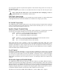
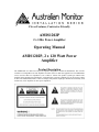
Clever Features, Contractor Friendly
AMIS1202P
2 x 120w Power Amplifier
Operating Manual
AMIS1202P, 2 x 120 Watt Power
Amplifier
Product Description
The AMIS1202P is a dual 120 watt power amplifier designed for commercial installations. The one unit
contains two independent 120 watt amplifiers for either stereo or dual zone applications. The AMIS1202P
can be used for either low impedance (4 or 8 ohm) or 70/100v line speaker systems per channel. The
amplifier can be mounted in a standard 19” equipment rack (rack ears supplied) or it can be used on a shelf
or table. The AMIS1202P features a line level input (with parallel output) per channel and is normally used
with mixers, mixer amplifiers or other power amplifiers.
Front Panel Features
Power Switch
The black rocker switch on the right hand side of the front panel is used to switch the amplifier on and off.
The ‘up’ position is on. When the amplifier is connected to an appropriate AC power source and is
switched on, the blue power LED will illuminate. This switch will not switch DC power on or off in DC
operation. In DC operation mode, the amplifier is always on and the blue power LED will always be
illuminated.
On LED
The blue “On” LED above the power switch will illuminate when the amplifier is connected to mains
power and is switched on. In 24vdc operation the LED will always be on.
Signal LED
The green “Signal” LED’s located next to the On LED indicate that the AMIS1202P is receiving audio
signal via its line level inputs. One LED is provided per channel. The signal LED’s are a simple way of
trouble-shooting installations especially in multi amplifier projects. At a glance the signal LED’s will
indicate that audio is reaching the amplifier.
Rack Mounting
The AMIS1202P is supplied with rack ears attached to allow mounting within a standard 19” equipment
rack. As is the case with almost all audio products, adequate ventilation and air flow is required. When
installing multiple AMIS amplifiers within the one rack, it is recommended that at least one rack unit of
ventilation space is left between every two amplifiers. For table or shelf mounting, the rack ears can be
removed using a screwdriver. Once the rack ears are removed, please reinstall the screws.
Rear Panel Features
AC Power Inlet
The operating voltage is 230/240 VAC @ 50 Hz. The 3 pin IEC power inlet is located on the bottom left of
the rear panel and accepts a standard mains power lead fitted with an IEC connector. Before plugging in a
power lead, please check the rear panel of the amplifier to ensure that the voltage switch is set correctly for
your part of the world.
The inlet is equipped with an in-built AC fuse holder fitted with an 4 Amp slow blow fuse plus a spare
fuse.
Please ensure that the mains power cord is disconnected before attempting to check or
replace this fuse. Power consumption is 400 VA (max).
230V/240V Slide Switch
The operating voltage of the amplifier is user selectable between 230V and 240V via a slide switch located
on the right of the AC inlet. This switch should be set to match the AC voltage of your country
24 Volt DC Power Inlet
The AMIS1202P feature optional 24VDC power to run off a battery back-up if required. This is connected
via the rear terminal strip. The front panel Power Switch will not switch DC power ‘on’ or ‘off’ in DC
operation. In this mode the amplifier is always ‘on’.
Speaker Output Terminal Strip
Located on the top left of the rear panel are the speaker output terminal strips. A terminal strip is provided
for each of the two amplifiers. Reading from left to right, the connections per terminal strip are:
COM Common or “-” for low impedance speaker loads (4 or 8 ohms).
4
The “+” for 4 ohm speaker loads (use with common)
8
The “+” for 8 ohm speaker loads (use with common)
COM
70
100
Common or “-” for 70v or 100v speaker loads (maximum load of 80 ohms at 100v)
The “+” for 70v line speaker loads (use with common)
The “+” for 100v line speaker loads (use with common)
Please ensure that the correct “Common” is used. Low impedance and 70/100v loads can be used
simultaneously but please pay careful attention to the overall speaker load. When used individually, the low
impedance load should be 4 ohms or higher while the 100v line load should not fall below 80 ohms per
amplifier. When both low impedance and 70/100v outputs are used simultaneously on the one amplifier,
ensure that neither output is loaded to maximum.
Level Control
Located next to the XLR input/output is a recessed screwdriver adjustable level control. One is provided
per amplifier channel. The level control is an input attenuation control normally used to match the amplifier
to a wide variety of input signals. In essence, the amplifier is designed to receive a 700mv input signal
however the level control can be used to increase the level for lower signals or decrease the level for higher
input signals. In normal use, the level control is used as a ‘set and forget’ master level control for the
amplifier.
XLR Audio Input and Parallel Output
The AMIS1202P includes both male and female 3 pin XLR connectors per channel. While the female is
normally used as the input to the amplifier, both XLR’s are connected in parallel so either will work. When
signal is connected to one XLR, the other XLR becomes a line level output allowing the input signal to be
distributed (split) to other amplifiers. In some projects, the same input may be looped through to multiple
amplifiers using this method. Up to 6 amplifiers can be looped together without any noticeable loss in level.
A distribution amplifier should be used when more than 6 amplifiers need to be looped.
The XLR’s are wired as follows: Pin 1: Shield. Pin 2: Hot, +, Positive. Pin 3: Cold, -, Negative
Fuse Sizes
Mains, 230VAC: 4 Amperes Slow Blow.
Notes:
The DC fuse is located on the circuit board. This is a feature of the AMIS series amplifier,
which is equipped with a current limiting circuit preventing excessive DC current, thus
eliminating the risk of blowing high tensions fuses. In the unlikely event that the DC fuse
actuates, the output transistors should be checked, as it is probable that the amplifier has been subjected to
very extreme conditions.
Important Safety Information
1. Save the carton and packing material even if the equipment has arrived in good condition. Should
you ever need to ship the unit, use only the original factory packing.
2. Read all documentation before operating your equipment. Retain all documentation for future
reference.
3. Follow all instructions printed on unit chassis for proper operation.
4. Do not spill water or other liquids into or on the unit, or operate the unit while standing in liquid.
5. Make sure power outlets conform to the power requirements listed on the back of the unit.
6. Do not use the unit if the electrical power cord is frayed or broken. The power supply cords should
be routed so that they are not likely to be walked on or pinched by items placed upon or against them,
paying particular attention to cords and plugs, convenience receptacles, and the point where they exit from
the appliance.
7. Always operate the unit with the AC ground wire connected to the electrical system ground.
Precautions should be taken so that the means of grounding of a piece of equipment is not defeated.
8. Mains voltage must be correct and the same as that printed on the rear of the unit. Damage caused
by connection to improper AC voltage is not covered by any warranty.
9. Have gain controls on amplifiers turned down during power-up to prevent speaker damage if there
are high signal levels at the inputs.
10. Power down & disconnect units from mains voltage before making connections.
11. Never hold a power switch in the “ON” position if it won’t stay there itself!
12. Do not use the unit near stoves, heat registers, radiators, or other heat producing devices.
13. Do not block fan intake or exhaust ports. Do not operate equipment on a surface or in an
environment which may impede the normal flow of air around the unit, such as a bed, rug, weathersheet,
carpet, or completely enclosed rack. If the unit is used in an extremely dusty or smoky environment, the
unit should be periodically “blown free” of foreign matter.
14. Do not remove the cover. Removing the cover will expose you to potentially dangerous voltages.
There are no user serviceable parts inside.
15. Do not drive the inputs with a signal level greater than that required to drive equipment to full
output.
16. Do not connect the inputs / outputs of amplifiers or consoles to any other voltage source, such as a
battery, mains source, or power supply, regardless of whether the amplifier or console is turned on or off.
17. Do not run the output of any amplifier channel back into another channel’s input. Do not
parallel- or series-connect an amplifier output with any other amplifier output.
Australian Monitor is not responsible for damage to loudspeakers for any reason.
18. Do not ground any red (“hot”) terminal. Never connect a “hot” (red) output to ground or to
another “hot” (red) output!
19. Non-use periods. The power cord of equipment should be unplugged from the outlet when left unused
for a long period of time.
20. Service Information Equipment should be serviced by qualified service personnel when:
A. The power supply cord or the plug has been damaged.
B. Objects have fallen, or liquid has been spilled into the equipment
C. The equipment has been exposed to rain
D. The equipment does not appear to operate normally, or exhibits a marked change in performance
E. The equipment has been dropped, or the enclosure damaged.
Engineered in Sydney, Australia
www.australianmonitor.com.au
International Sales & Corporate Head Office
Private Bag 149, Silverwater NSW 1811
149 Beaconsfield Street, Silverwater NSW 2128
Australia
Ph: 61-2- 9647 1411
Fax: 61-2-9748 2537
E-mail: [email protected]