1
BB0.467.012-10
5
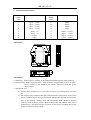
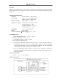
STS49 Terminal Functions
Terminal
Safety
Zone
Function
Terminal
Danger
Zone
Function
1
2
3
4
5
6
7
8
Input +V(ch1)
Input -V(ch1)
Input +V(ch2)
Input -V(ch2)
Power +V
Power -V
Empty
Empty
9
10
11
12
13
14
15
16
Empty
Empty
Empty
Empty
Output +V(ch1)
Output -V(ch1)
Output +V(ch2)
Output -V(ch2)
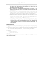
4 3 2 1
9 10 11 12
13 14 15 16
8 7 6 5
112
6 Dimensions
7 Installations
7.1 Guideway:Isolate barrier is installed on the standard international generic M35 Guideway.
7.2 Terminal lead:Rubber insulated cables,cable insulation strength should be above AC500V,
traverse number of lead should not less than30,and cross-section area greater
than 0.75mm2
7.3 Installation notes
a) Isolate barrier should be put in a safe place to ensure the cleaning and no corrosive
gas.
b) The circuit wiring of intrinsic ends (blue) and non-intrinsic ends (yellow) of the isolate
barrier is prohibited from wrong and confusion. The intrinsic safe leads should use the
blue as the marking; intrinsic leads and non-intrinsic leads should be installed
separately in the leads slot, and use different casing tubes. The intrinsic safety side of
isolate barrier is not allowed to have a mixture of other power, including other power
supply with intrinsic safety current.
2