1
DALSA • 7075 Place Robert-Joncas, Suite 142 • Montreal, Quebec, Canada • H4M 2Z2
http://www.dalsa.com/mv
PC2-CamLink
User's Manual
Part number OC-PC2M-CUM00
Edition 2.31
*OC-PC2M-CUM00*
NOTICE
© 2001-2010 DALSA Corp. All rights reserved.
This document may not be reproduced nor transmitted in any form or by any means, either electronic
or mechanical, without the express written permission of DALSA Corp. Every effort is made to ensure
the information in this manual is accurate and reliable. Use of the products described herein is
understood to be at the user's risk. DALSA Corp. assumes no liability whatsoever for the use of the
products detailed in this document and reserves the right to make changes in specifications at any time
and without notice.
Microsoft is a registered trademark; Windows®, Windows® XP, Windows® Vista, and Windows® 7
are trademarks of Microsoft® Corporation.
All other trademarks or intellectual property mentioned herein belong to their respective owners.
Manual revision: May 27, 2010
Document Number: OC-PC2M-CUM00
Printed in Canada
Contents
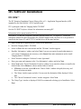
INTRODUCTION ................................................................................................................... 1
OVERVIEW OF THE MANUAL ........................................................................................ 1
About the Manual ......................................................................................... 2
Using the Manual ......................................................................................... 2
PART I: PC2-CAMLINK BOARD ....................................................................................... 3
THE PC2-CAMLINK ..................................................................................................... 5
Components & Part Numbers....................................................................... 5
EC & FCC Certificate of Conformity ........................................................... 6
PC2-CAMLINK–INSTALLATION OVERVIEW ................................................................. 7
Warning! (Grounding Instructions).............................................................. 7
Before Installing ........................................................................................... 7
Configuration Jumpers ................................................................................. 7
SAPERA LT LIBRARY INSTALLATION ........................................................................... 8
INSTALLING PC2-CAMLINK HARDWARE AND DRIVER ................................................ 8
In a Windows XP, Windows Vista, or Windows 7 System ............................ 8
UPGRADING SAPERA OR ANY BOARD DRIVER ............................................................. 9
Board Driver Upgrade Only......................................................................... 9
Sapera and Board Driver Upgrades........................................................... 10
COM Port Assignment ................................................................................ 10
Configuring Sapera .................................................................................... 12
IFC SOFTWARE INSTALLATION .................................................................................. 15
IFC-SDK™ ................................................................................................. 15
Configuring Serial Port Under IFC............................................................ 17
Upgrading Onboard Firmware .................................................................. 20
THEORY OF OPERATION ............................................................................................. 21
PC2-CamLink Flow Diagram..................................................................... 21
Camera Control and Synchronization ........................................................ 23
Camera Interface ........................................................................................ 42
Input LUT ................................................................................................... 43
Data Port Sequencer................................................................................... 44
Window Generator...................................................................................... 47
YCrCb Engine............................................................................................. 48
PCI Controller ............................................................................................ 49
Visual Status LEDs ..................................................................................... 52
Parallel I/O................................................................................................. 53
PC2-CamLink User's Manual
Contents • i
Acquisition Interrupts ................................................................................. 55
Error Support Interrupts............................................................................. 59
Camera Power ............................................................................................ 60
Trigger-to-Image Reliability ....................................................................... 60
TECHNICAL REFERENCE ............................................................................................. 64
Block Diagram ............................................................................................ 64
Hardware Specifications............................................................................. 65
PC2-CamLink Connector and Jumper Locations....................................... 67
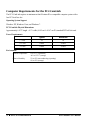
Computer Requirements for the PC2-CamLink .......................................... 74
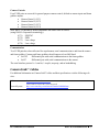
CAMERA LINK™ INTERFACE ..................................................................................... 75
Camera Link™ Overview ........................................................................... 75
Data Port Summary .................................................................................... 76
Camera Signal Summary ............................................................................ 76
Camera Link™ Cables................................................................................ 77
PART II: SAPERA LT ......................................................................................................... 79
SAPERA SERVER AND PARAMETERS ........................................................................... 81
SAPERA SOFTWARE EXAMPLE.................................................................................... 91
Grab Demo Overview ................................................................................. 91
Using the Grab Demo ................................................................................. 92
Using Sapera CamExpert with PC2-CamLink............................................ 95
PART III: IFC ....................................................................................................................... 99
IFC SOFTWARE EXAMPLES ...................................................................................... 101
IFC Examples for PC2-CamLink.............................................................. 101
PC-CAMLINK IFC PARAMETERS COMPARISON ....................................................... 103
Overview ................................................................................................... 103
PART IV: TROUBLESHOOTING AND SUPPORT ...................................................... 111
TROUBLESHOOTING ................................................................................................. 113
Overview ................................................................................................... 113
Tools.......................................................................................................... 113
Symptoms .................................................................................................. 115
DALSA CONTACT INFORMATION ............................................................................ 119
Sales Information ...................................................................................... 119
TECHNICAL SUPPORT ............................................................................................... 120
GLOSSARY OF TERMS ................................................................................................... 121
INDEX .................................................................................................................................. 125
ii • Contents
PC2-CamLink User's Manual
Introduction
Overview of the Manual
•
•
•
•
Part I: PC2-CamLink Board
•
The PC2-CamLink
Description of the PC2-CamLink board and its software as well as PC2-CamLink
package contents list.
Installing the PC2-CamLink
Hardware installation instructions as well as information concerning jumper
configuration and connecting cameras and devices.
Sapera LT Software Installation
Illustrates how to install Sapera LT and the PC2-CamLink device driver as well as
information concerning COM Port assignment and how to configure Sapera LT.
IFC Software Installation
Illustrates how to install IFC as well as information concerning upgrading onboard
firmware, configuring the serial port, and starting Camera Configurator.
Theory of Operation
Detailing PC2-CamLink features.
Technical Reference
PC2-CamLink specifications. Includes connector and pinout diagrams.
Camera Link™ Interface
Information concerning the Camera Link™ specification.
Part II: Sapera LT
•
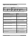
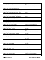
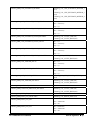
Sapera Server and Parameters
Lists the Sapera server available and describes the Sapera parameters and values
supported by PC2-CamLink.
Sapera Software Examples
Describes in detail the Sapera Grab Demo.
Part III: IFC
•
IFC Software Examples
Two board specific examples of IFC software features using the PC2-CamLink.
PC-CamLink IFC Parameters Comparison
Lists PC-CamLink parameters compared with their corresponding PC2-CamLink
parameters.
Part IV: Troubleshooting and Support
•
Troubleshooting
Offers suggestions for resolving installation or usage problems.
PC2-CamLink User's Manual
Introduction • 1
DALSA Contact Information
Phone numbers, web sites, and important email addresses.
About the Manual
This manual exists in Adobe Acrobat (PDF) format. The PDF format makes full use of hypertext
cross-references and include links to the DALSA home page on the Internet located at
http://www.dalsa.com/mv, accessed using any web browser.
Using the Manual
File names, directories, and Internet sites will be in bold text
(e.g., image2.bmp, c:\IFC, http://www.dalsa.com).
Text that must be entered using the keyboard will be in typewriter-style text
(e.g., c:\temp).
Menu and dialog actions will be indicated in bold text in the order of the instructions to be executed,
with each instruction separated by bullets. For example, going to the File menu and choosing Save
would be written as File•Save.
2 • Introduction
PC2-CamLink User's Manual
Part I: PC2-CamLink Board
PC2-CamLink User's Manual
Part I: PC2-CamLink Board • 3
4 • Part I: PC2-CamLink Board
PC2-CamLink User's Manual
The PC2-CamLink
The PC2-CamLink is a half slot frame grabber that grabs images from a single base digital Camera
Link™ camera to host memory for processing. The board was designed for cost-effective
performance. Both linescan and area scan cameras are supported. Up to two channels are supported.
Note that RGB is not supported.
Components & Part Numbers
The following table lists the components and part numbers for the PC2-CamLink:
Item
Part Number
Board
PC2-CamLink
OC-PC20-C0000
Cables & Accessories
Camera Link™ Video Input Cable (optional product):
1 meter
OC-COMC-CLNK0
2 meter
OC-COMC-CLNK6
Optional Cable
Floppy power connector*
OC-COMC-POW03
Documentation
PC2-CamLink User’s manual
OC-PC2M-CUM00
IFC-SDK Software manual
403-00004-00
Camera Configurator® User's manual
405-00006-00
*The floppy power connector can be ordered by contacting DALSA. See “DALSA Contact
Information” (on page 119) for further information.
PC2-CamLink User's Manual
Part I: PC2-CamLink Board • 5
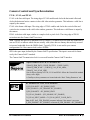
EC & FCC Certificate of Conformity
6 • Part I: PC2-CamLink Board
PC2-CamLink User's Manual
PC2-CamLink–Installation Overview
Warning! (Grounding Instructions)
Static electricity can damage electronic components. Please discharge any static electrical charge by
touching a grounded surface, such as the metal computer chassis, before performing any hardware
installation.
If you do not feel comfortable performing the installation, consult a qualified computer technician.
Never remove or install any hardware component with the computer power on. Disconnect the
power cord from the computer to disable the power standby mode. This prevents the case where
some computers unexpectedly power up when a board is installed.
Before Installing
Make certain that a free PCI expansion slot is available PC2-CamLink is compatible with either 5V or
3.3V PCI slots..
Confirm that you are using Windows XP, Windows Vista, or Windows 7. Other versions of Windows
or non-Microsoft operating systems are not supported.
Configuration Jumpers
PC2-CamLink is equipped with two type of jumpers:
• Opto-coupler jumper
• Camera power jumper
The opto-coupler jumper includes four connectors divided into two sets of two: opto1 (J5 and J6) and
opto2 (J3 and J4). This jumper selects specific voltage power to the opto-coupler by means of jumper
configuration. See “J3, J4, J5, J6: Opto-coupler Voltage Selector” (on page 70) for more information.
Factory default is 0-6V for TTL voltage level connections.
The camera power jumper, J13, controls camera power on the DB-15 connector by means of jumper
configuration. For important information concerning this topic, see the “Camera Power” section (on
page 60). Factory default is no voltage.
PC2-CamLink User's Manual
Part I: PC2-CamLink Board • 7
Sapera LT Library Installation
Note: to install Sapera LT and the PC2-CamLink device driver, logon to the workstation as an
administrator or with an account that has administrator privileges.
The Sapera LT Development Library (or ‘runtime library’ if application execution without
development is preferred) must be installed before the PC2-CamLink device driver.
•
Insert the DALSA Sapera CD-ROM. If AUTORUN is enabled on your computer, the DALSA
installation menu is presented.
•
If AUTORUN is not enabled, use Windows Explorer and browse to the root directory of the CDROM. Execute launch.exe to start the DALSA installation menu and install the required Sapera
components.
•
The installation program will prompt you to reboot the computer.
Refer to Sapera LT User’s Manual for additional details about Sapera LT.
Installing PC2-CamLink Hardware and Driver
In a Windows XP, Windows Vista, or Windows 7 System
•
Turn the computer off, disconnect the power cord (disables power standby mode), and open the
computer chassis to allow access to the expansion slot area.
•
Install the PC2-CamLink into a free PCI slot.
•
Close the computer chassis and turn the computer on. Driver installation requires administrator
rights for the current user of the computer.
•
Windows will find the PC2-CamLink and start its Found New Hardware Wizard. Click on the
Cancel button to close the Wizard Application.
•
Insert the DALSA Sapera CD-ROM. If AUTORUN is enabled on your computer, the DALSA
installation menu is presented. Install the PC2-CamLink driver.
•
If AUTORUN is not enabled, use Windows Explorer and browse to the root directory of the CDROM. Execute launch.exe to start the DALSA installation menu and install the PC2-CamLink
driver. Note, if you are using Windows Vista or Windows 7 with the User Account Control
feature enabled, a dialog is displayed when you execute launch.exe; click Allow to continue with
the driver installation.
•
Choose the device driver setup type, full installation (required for application development) or
runtime installation (supports application execution only).
•
When using Windows XP, if a message stating that the PC2-CamLink software has not passed
Windows Logo testing is displayed, click on Continue Anyway to finish the PC2-CamLink
driver installation. Reboot the computer if prompted to do so.
8 • Part I: PC2-CamLink Board
PC2-CamLink User's Manual
•
When using Windows Vista or Windows 7, a message asking to install the DALSA device
software is displayed. Click Install.
Upgrading Sapera or any Board Driver
When installing a new version of Sapera or a DALSA acquisition board driver in a computer with a
previous installation, the current version must be un-installed first. Upgrade scenarios are described
below.
Board Driver Upgrade Only
Minor upgrades to acquisition board drivers are typically distributed as ZIP files available in the
DALSA web site http://www.dalsa.com/. Board driver revisions are also available on the next release
of the Sapera CD-ROM.
Often minor board driver upgrades do not require a new revision of Sapera. To confirm that the
current Sapera version will work with the new board driver:
•
Check the new board driver ReadMe file before installing, for information on the minimum
Sapera version required.
•
If the ReadMe file does not specify the Sapera version, contact DALSA Technical Support (see
"Technical Support" on page 120).
PC2-CamLink User's Manual
Part I: PC2-CamLink Board • 9
To upgrade the board driver only:
•
Logon the computer as an administrator or with an account that has administrator privileges.
•
From the Windows start menu select Start • Control Panel • Add or Remove Programs.
•
Select the DALSA PC2-CamLink Device Driver, click Remove, and then in the InstallShield
dialog click on Remove to uninstall the board driver.
•
When the driver un-install is complete, reboot the computer is prompted to do so.
•
Logon the computer as an administrator again.
•
Install the new board driver. Run Setup.exe if installing manually from a downloaded driver file.
•
Note that you can not install a DALSA board driver without Sapera LT installed on the computer.
Sapera and Board Driver Upgrades
When both Sapera and the acquisition board driver are upgraded, follow the procedure described
below.
•
Logon the computer as an administrator or with an account that has administrator privileges.
•
From the Windows start menu select Start • Control Panel • Add or Remove Programs.
•
Select the DALSA PC2-CamLink Device Driver, click Remove, and then in the InstallShield
dialog click on Remove to uninstall the board driver.
•
From the Windows start menu select Start • Control Panel • Add or Remove Programs.
•
Select the DALSA Sapera LT program, click Remove, and then in the InstallShield dialog click
on Remove to uninstall Sapera.
•
Reboot the computer and logon the computer as an administrator again.
•
Install the new versions of Sapera and the board driver as if this was a first time installation. For
installation procedures, see "Sapera LT Library Installation" on page 8 and "Installing PC2CamLink Hardware and Driver" on page 8 for installation procedures.
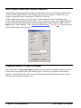
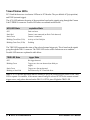
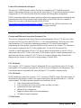
COM Port Assignment
The lower section of the Sapera Configuration program screen contains the serial port configuration
menu. Configure as follows:
•
Open the ‘Sapera Configuration’ program (Start•Programs•DALSA•Sapera LT•Sapera
Configuration).
•
Use the Physical Port drop menu to select the Sapera board device from all available Sapera
boards using serial ports (when more then one board is in your system).
•
Use the Maps to drop menu to assign an available COM number to the Sapera board serial port.
•
Click on the Save Settings Now button and then the Close button. You are prompted to reboot
your computer to enable serial port mapping.
10 • Part I: PC2-CamLink Board
PC2-CamLink User's Manual
•
The PC2-CamLink serial port (mapped to COM3 in this example) is available as a serial port to
any serial port application for camera control. Note that this serial port is not listed in the
Windows•Control Panel•System Properties•Device Manager because it is a logical serial port
mapping.
PC2-CamLink User's Manual
Part I: PC2-CamLink Board • 11
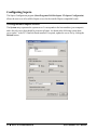
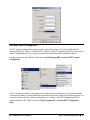
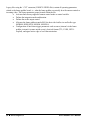
Configuring Sapera
The Sapera Configuration program (Start•Programs•DALSA•Sapera LT•Sapera Configuration)
allows the user to see all available Sapera servers for the installed Sapera-compatible boards.
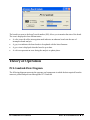
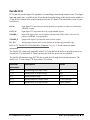
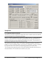
Viewing Installed Sapera Servers
The System entry represents the system server. It corresponds to the host machine (your computer)
and is the only server that should be present at all times. As shown in the following screen shoot,
server index 1 is the PC2-CamLink board installed. If required, update the server list by clicking the
Refresh button.
12 • Part I: PC2-CamLink Board
PC2-CamLink User's Manual
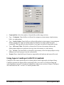
Increasing Contiguous Memory for Sapera Resources
The Contiguous Memory section lets the user specify the total amount of contiguous memory (a
block of physical memory occupying consecutive addresses) reserved for the resources needed for
Sapera buffer allocation and Sapera messaging. For both items, the Requested value dialog box
shows the default driver memory setting while the Allocated value displays the amount of contiguous
memory that has been allocated successfully. The default values will generally satisfy the needs of
most applications.
The Sapera buffer values determine the total amount of contiguous memory reserved at boot time for
the allocation of dynamic resources used for host frame buffer management, such as DMA descriptor
tables as well as other kernel needs. Adjust this value higher if your application generates any out-ofmemory error while allocating host frame buffers. You can approximate the amount of contiguous
memory required as follows:
•
Calculate the total amount of host memory used for frame buffers
( number of frame buffers • number of pixels per line • number of lines • (2 - if buffer
is 10 or 12 bits) ).
•
Provide 1MB for every 256MB of host frame buffer memory required.
•
Add an additional 1MB if the frame buffers have a short line length, e.g., 1k or less
(increased number of individual frame buffers requires more resources).
•
Add an additional 2MB for various static and dynamic Sapera resources.
•
Test for any memory error when allocating host buffers. Simply select the Buffer button in the
‘General Options’ section of the “Grab Demo Main Window” (see page 93) of the Sapera Grab
Demo program to open the Buffer window (see “Using the Grab Demo” on page 92) to allocate
the number of host buffers required for your acquisition source. Feel free to test the maximum
host buffer limit possible in your host system—Grab Demo will not crash when the requested
number of host frame buffers cannot be allocated.
PC2-CamLink User's Manual
Part I: PC2-CamLink Board • 13
Host Computer Frame Buffer Memory Limitations
When planning a Sapera application and the host frame buffers used, as well as other Sapera memory
resources, do not forget the needs of the Windows operating system memory. Window XP, as an
example, should always have a minimum of 128MB for its own use.
A Sapera application using scatter-gather buffers could consume most of the remaining system
memory. When using frame buffers allocated as a single contiguous memory block, typical limitations
are one third of the total system memory with a maximum limit of approximately 100MB. Click on
Buffer under “General Options” in the “Grab Demo Main Window” (see page 93) to select from a list
of host buffer memory allocation types.
Contiguous Memory for Sapera Messaging
The current value for Sapera messaging determines the total amount of contiguous memory reserved
at boot time for message allocation. This memory space is used to store arguments when a Sapera
function is called. Increase this value if you are using functions with large arguments, such as arrays,
and when experiencing any memory errors.
14 • Part I: PC2-CamLink Board
PC2-CamLink User's Manual
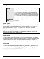
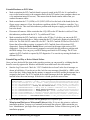
IFC Software Installation
IFC-SDK™
The IFC (Imaging Foundation Classes) library offers a C++ Application Program Interface (API)
intended for use with DALSA’s PC2-CamLink board.
IFC is packaged within the “Imaging Studio CD-ROM”.
See the IFC-SDK™ Software Manual for information concerning IFC.
Information in this manual matches IFC 5.8.
Note that PC2-CamLink is supplied with either Imaging Studio (IFC) or Sapera LT. Follow the
installation instructions that correspond to the software supplied with your board. It is not possible to
install both the Sapera LT and IFC PC2-CamLink driver on the same machine.
•
Make certain that all applications are closed before installation.
•
Insert the ‘Imaging Studio’ CD-ROM.
•
Select on Next after auto-start initiates and the ‘Welcome’ window appears.
•
Read the ‘Information’ window and select Next if you are not required to make adjustments to
your system. If adjustments are necessary, select Cancel, then make adjustments and re-install
‘Imaging Studio’ CD-ROM.
•
Select Yes after reading the ‘Software License Agreement’.
•
Enter your name and company in the ‘User Information’ window and select Next.
•
Select Next in the ‘Choose Destination Location’ window if you want the software to install in the
default folder. Select Browse to choose another folder if desired.
• If Browse is selected, select OK in the ‘Choose Folder’ window after path, directory, and
driver selections are made.
• The ‘Setup’ window opens and asks if it can create the destination folder displayed. Select
Yes.
• The ‘Choose Destination Location’ window reappears. Select Next.
•
The ‘Setup Type’ window is displayed. DALSA recommends selecting typical installation. Select
Next.
PC2-CamLink User's Manual
Part I: PC2-CamLink Board • 15
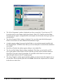
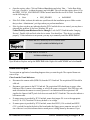
•
The ‘Select Components’ window is displayed (see above screen shot). If you do not see PC2CamLink in the list, select Next to display more boards. Check PC2-CamLink and select Next.
Note that only the support, configuration files and examples for the board(s) chosen get copied to
your hard drive.
•
The ‘Select Program Folder’ window is displayed. You can either retain the default program
folder or create a new one. Select Next for the installation to begin.
•
A window appears asking if you want Acrobat Reader to view and print manuals installed with
the ‘Imaging Studio’ CD-ROM. Select Yes if you do not already have Acrobat Reader installed in
your system.
•
Select Yes or No after the window appears asking to view readme files.
•
The ‘Service Pack Update Check’ window is displayed. This allows you to check for an IFC
service pack update via the DALSA web site. Note that you need an active Internet connection.
Select Yes if you want to check for an update. It is possible to check later for a service pack
update through a shortcut in the IFC program group.
•
The ‘Setup Complete’ window appears and asks whether you want to restart the computer now or
at a later time. Choose desired option and select Finish. Note that the computer must be restarted
for the drivers to take effect.
16 • Part I: PC2-CamLink Board
PC2-CamLink User's Manual
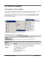
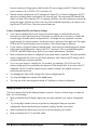
Configuring Serial Port Under IFC
Optional COM Port Assignment
The IFC “Set Board COM Port” application tool is used to assign the COM Port. Run the program
from the Windows Start menu: Start•ProgramsIFC version 5.8•Tools•Set Board Com Port.
The ‘Set Image Capture Board Uart ComX Port’ window appears. The PC2-CamLink board/s appear/s
in the ‘Select Board’ window. See screenshot below.
To assign a standard COMx name to PC2-CamLink:
PC2-CamLink User's Manual
Part I: PC2-CamLink Board • 17
•
Under ‘Select Board’ choose the PC2-CamLink board (CL2 prefix) you want to map (CL20 is the
first PC2-CamLink board, CL21 is the second, …).
•
Under ‘Select COM Port Number’ assign an unused COM Port number to that PC2-CamLink
board and click Set.
•
Click Close.
•
Reboot PC for the new settings to take effect.
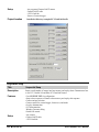
Setup Example Using HyperTerminal
•
Run HyperTerminal and type a name for the new connection when prompted, click OK.
•
Select the COM Port you want to connect with within the following dialog screen. In this example
the PC2-CamLink serial port was previously mapped to COM3 by the IFC Serial Port
Configuration program.
•
HyperTerminal opens a dialog box where the COM Port properties are configured (see screenshot
below). Adjust settings as required by the connected camera. Note that the PC2-CamLink serial
port does not support hardware flow control.
18 • Part I: PC2-CamLink Board
PC2-CamLink User's Manual
Starting Camera Configurator
The IFC Camera Configurator® program is the camera interfacing tool for frame grabber boards
supported by the IFC library, such as the PC2-CamLink. Camera Configurator® generates the required
camera configuration file (yourconfig.txt) based on the timing and control parameters entered.
Run the program from the Windows Start menu: Start•ProgramsIFC version 5.8•IFC Camera
Configurator.
The live acquisition window is an important tool within Camera Configurator. It performs immediate
verification on timing or control parameters without the need to run a separate acquisition program. An
overview on how to use the Camera Configurator® is available via the IFC Configurator help file
installed within the IFC folder accessed at Start•Programs•IFC version 5.8•IFC Configurator
Help.
PC2-CamLink User's Manual
Part I: PC2-CamLink Board • 19
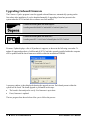
Upgrading Onboard Firmware
The Firmware Update program is used to upgrade onboard firmware, automatically opening on the
first reboot after installation. It can be launched manually if upgrading a board not present in the
system when the PC2-CamLink driver software was first installed.
Location of Board Update tool under Sapera:
Start•Programs•DALSA•PC2-CamLink•PC2-CamLink Update Tool
IFC
Location of Board Update tool under IFC:
Start•Programs•IFC 5.8.0.0•Tools•CorBoardUpdate for PC2-CamLink
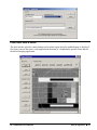
Firmware Update displays a list of all products it supports, as shown in the following screenshot. To
update all supported products, click Yes and all PC2-CamLinks currently installed within the computer
will be updated with the latest firmware available within the installation CDROM.
A progress window is then displayed showing the upgrade process. Each board present within the
system will be listed. The board upgrade is performed in two steps:
•
The board is first analyzed to verify if its firmware is up-to-date.
•
If not, firmware is updated.
The two progress bars shown below allow you to follow the process.
20 • Part I: PC2-CamLink Board
PC2-CamLink User's Manual
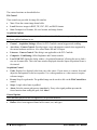
The board icon, next to the board’s serial number (SN), allows you to monitor the state of the board.
The icon is displayed in four different states:
•
A white icon with a blue interrogation mark indicates an unknown board state because of
incomplete board analysis.
•
A gray icon indicates the board needs to be updated with the latest firmware.
•
A green icon is displayed when the board is up-to-date.
•
A red icon represents an error during the analysis or update phase.
Theory of Operation
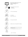
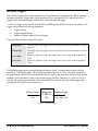
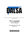
PC2-CamLink Flow Diagram
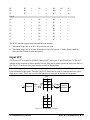
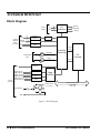
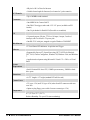
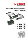
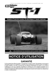
The following diagram represents the sequence and components in which the data acquired from the
camera is piloted and processed through the PC2-CamLink.
PC2-CamLink User's Manual
Part I: PC2-CamLink Board • 21
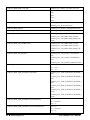
Camera
Control
y Supports EXSYNC and PRIN camera control signals
y 2 Opto or 2 LVDS frame trigger inputs
y Shaft-Encoder LVDS inputs
y Serial Port
Camera
y
y
y
1 Base CameraLink, areascan or line scan
1 or 2 channel(s)
8 to 16-bit per pixel
ILUT
y
1 LUT for each CameraLink port
Data Port
Sequencer
y 1 or 2 channel(s)
y Optional truncation to 8-bit
Window
Generator
y
Creates region of interest (ROI)
YCrCb
Engine
y
Optionally converts to 16-bit padded YCrCb for display
PCI
Controller
y
y
Scatter/gather engine that grabs into host logical memory
minimizing CPU usage
32-bit/33 MHz high-speed PCI interface (5V and 3.3V)
To PCI bus
Figure 1: Flow Diagram
22 • Part I: PC2-CamLink Board
PC2-CamLink User's Manual
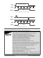
Camera Control and Synchronization
FVAL, LVAL, and DVAL
LVAL is the line valid input. The rising edge of LVAL enables and clocks the horizontal offset and
clocks the horizontal active counters in the valid video window generator. This indicates a valid line is
output by the camera.
FVAL is the frame valid input. The rising edge of FVAL enables and clocks the vertical offset and
vertical active counters in the valid video window generator. This indicates a valid frame is output by
the camera.
DVAL is the data valid input, similar to a sample clock or pixel clock. The rising edge of DVAL
writes data into the Camera Link™ receivers.
Note: CameraLink specifies a minimum clock of 20MHz. If a camera does not reach this bandwidth, it
can use DVAL to indicate which data are actually valid (other data are dummy data and only are used
to increase bandwidth above the 20MHz limit). Typically, DVAL is not used in your camera
configuration file if the camera clock is above 20MHz.
SPR is the spare input, defined by the Camera Link™ specification. This input is reserved for future
use by the Camera Link™ standard.
The Camera Link™ transmission clock is recovered from the Camera Link™ interface.
Sapera Parameters for FVAL, LVAL and DVAL:
CORACQ_PRM_DATA_VALID_ENABLE = {TRUE, FALSE}
CORACQ_PRM_SCAN = { CORACQ_VAL_SCAN_AREA,
CORACQ_VAL_SCAN_LINE}
Note: In Sapera, polarity of FVAL, LVAL and DVAL follows the CameraLink standard
(always active high).
In CamExpert, these parameters are located under the ‘Basic Timing Parameters’ tab.
IFC
IFC Parameters for FVAL, LVAL and DVAL:
P_LEN_POLARITY = IFC_RISING_EDGE
P_FEN_ENABLE = {IFC_DISABLE, IFC_ENABLE}
P_FEN_POLARITY = IFC_RISING_EDGE
CL2_DVAL_ENABLE = {IFC_DISABLE, IFC_ENABLE}
CL2_DVAL_INPUT_MODE = CL2_DVAL_INPUT_VALID_DATA
Note: In IFC, the P_FEN_ENABLE parameter indicates if the camera is area scan
(P_FEN_ENABLE = IFC_ENABLE) or linescan (P_FEN_ENABLE = IFC_DISABLE).
PC2-CamLink User's Manual
Part I: PC2-CamLink Board • 23
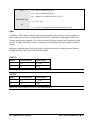
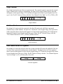
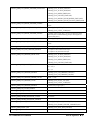
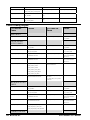
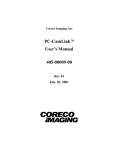
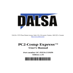
CC1-CC4
Four camera controls are reserved to act as general-purpose camera controls. They are referred to in
the Camera Link™ standard as CC1, CC2, CC3 and CC4. Each of the four CC lines can be
dynamically connected to four possible signal sources:
• The EXSYNC pulse generator
• The PRIN pulse generator
• A static low voltage level
• A static high voltage level
This is illustrated in the figure below:
EXSYNC
PRIN
M
U
X
1
CC
0
Figure 2: MUX
Sapera Parameters for Camera Control Selection:
CC pins are easily controlled from CamExpert under the ‘Advanced Control
Parameters’ tab. Each CC can take five different values:
IFC
1.
Not Used (keep previous state)
2.
High
3.
Low
4.
Pulse #0 (PRIN)
5.
Pulse #1 (EXSYNC)
IFC Parameters for Camera Control Selection:
CL2_CAM_CTL1_SIGNAL = {CL2_CCTL_FIXED_LOW,
CL2_CCTL_FIXED_HIGH, CL2_CCTL_EXSYNC, CL2_CCTL_PRI}
CL2_CAM_CTL2_SIGNAL = {CL2_CCTL_FIXED_LOW,
CL2_CCTL_FIXED_HIGH, CL2_CCTL_EXSYNC, CL2_CCTL_PRI}
CL2_CAM_CTL3_SIGNAL = {CL2_CCTL_FIXED_LOW,
CL2_CCTL_FIXED_HIGH, CL2_CCTL_EXSYNC, CL2_CCTL_PRI}
CL2_CAM_CTL4_SIGNAL = {CL2_CCTL_FIXED_LOW,
CL2_CCTL_FIXED_HIGH, CL2_CCTL_EXSYNC, CL2_CCTL_PRI}
24 • Part I: PC2-CamLink Board
PC2-CamLink User's Manual
Note: The EXSYNC and PRIN pulse generators are fired by the selected trigger source. For area scan,
if no trigger source is enabled, the pulse generators are triggered as soon as the previous frame has
been captured. This is similar to a free-running mode where EXSYNC and PRIN are generated as fast
as possible. For linescan cameras, a line trigger source is required to get an EXSYNC or PRIN pulse.
You can select the user timer to generate a trigger at a specified rate.
The EXSYNC and PRIN pulse generators can be combined to generate a double-pulse on the same
camera control pin.
Each pulse generator has the following capabilities:
• Programmable polarity (active high or active low)
• Programmable delay from trigger event (up to 65 seconds)
• Programmable duration (up to 65 seconds)
Timer granularity is 1µs when the delay and duration values are below 65ms. Granularity falls to 1ms
for delay or duration above 65ms. Delay and duration always have the same granularity.
Each timer for area scan can be started on the following trigger events:
• Opto1 or Opto2 trigger pins
• LVDS1 or LVDS2 trigger pins
• SW trigger
• User timer
Each timer for line scan can be started on the following trigger events:
• Shaft encoder
• User timer
Note: Both pulse generators are always fired by the same trigger source.
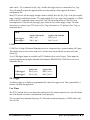
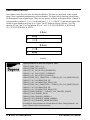
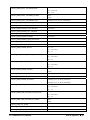
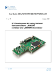
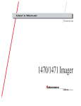
EXSYNC
The external synchronization output (EXSYNC) can control camera timing and integration. EXSYNC
is a programmable pulse generator: the delay from the trigger and the pulse duration are programmable
from 1µs to 65 seconds. The polarity of the EXSYNC output is programmable.
EXSYNC Pulse Generator
Ext. Trigger
EXSYNC
Offset
Active
Time
Figure 3: EXSYNC Pulse Generator
PC2-CamLink User's Manual
Part I: PC2-CamLink Board • 25
The EXSYNC signal can be selected as an output on any of the four camera control lines on the
Camera Link™ connector.
Note: The EXSYNC pulse is always fired from the selected trigger event.
EXSYNC can be used as the exposure input to some area scan cameras. EXSYNC might also be used
as the line transfer input on some linescan cameras.
Sapera Parameters for EXSYNC:
Refer to Time Integration method in the Sapera Acquisition Parameters Reference
manual. EXSYNC is typically designated by pulse #1 in the various time integration
methods.
CORACQ_PRM_TIME_INTEGRATE_METHOD: Method to use for time integration
CORACQ_PRM_TIME_INTEGRATE_PULSE1_DELAY: Pulse offset from trigger
event
CORACQ_PRM_TIME_INTEGRATE_PULSE1_DURATION: Size of pulse
CORACQ_PRM_TIME_INTEGRATE_PULSE1_POLARITY =
{CORACQ_VAL_ACTIVE_LOW, CORACQ_VAL_ACTIVE_HIGH}
Note: Sapera also supports Camera Reset and Camera Trigger methods. Refer to the
Sapera Acquisition Parameters Reference manual for more information.
In CamExpert, these parameters are found under the ‘Advanced Control Parameters’
tab. Select one of the camera control methods (camera reset, camera trigger, or time
integration).
IFC
IFC Parameters for EXSYNC:
CL2_EXSYNC_ENABLE = {IFC_DISABLE, IFC_ENABLE}
CL2_EXSYNC_POLARITY = {IFC_ACTIVE_LOW, IFC_ACTIVE_HIGH}
CL2_EXT_SYNC_OFFSET_TIME: Pulse offset from trigger event
CL2_EXT_SYNC_ACTIVE_TIME: Size of pulse
CL2_ COMBINE_EXSYNC_PRI = {IFC_DISABLE, IFC_ENABLE}
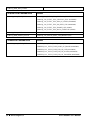
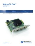
PRIN
The PRIN output signal is used by some cameras to control the integration time. PRIN is a
programmable pulse generator: the delay from the trigger and the pulse duration are programmable
from 1µs to 65seconds. The polarity of the PRIN output is programmable.
26 • Part I: PC2-CamLink Board
PC2-CamLink User's Manual
PRIN Pulse Generator
Ext. Trigger
PRIN
Active
Time
Offset
Figure 4: PRIN Pulse Generator
The PRIN signal can be selected as an output on any of the four camera control lines on the Camera
Link™ connector.
Note: The PRIN pulse is always fired from the selected trigger event.
Sapera Parameters for PRIN:
Refer to Time Integration method in the Sapera Acquisition Parameters Reference
manual. PRIN is typically designated by pulse #0 in the various time integration
methods.
CORACQ_PRM_TIME_INTEGRATE_METHOD: Method to use for time integration
CORACQ_PRM_TIME_INTEGRATE_PULSE0_DELAY: Pulse offset from trigger
event
CORACQ_PRM_TIME_INTEGRATE_PULSE0_DURATION: Size of pulse
CORACQ_PRM_TIME_INTEGRATE_PULSE0_POLARITY =
{CORACQ_VAL_ACTIVE_LOW, CORACQ_VAL_ACTIVE_HIGH}
Note: Sapera also support Camera Reset methods and Camera Trigger methods. Refer to
the Sapera Acquisition Parameters Reference manual for more information.
In CamExpert, these parameters are found under the ‘Advanced Control Parameters’
tab. Select one of the camera control methods (camera reset, camera trigger, or time
integration).
IFC
IFC Parameters for PRIN:
CL2_PRI_ENABLE = {IFC_DISABLE, IFC_ENABLE}
CL2_PRI_POLARITY = {IFC_ACTIVE_LOW, IFC_ACTIVE_HIGH}
CL2_PRI_OFFSET_TIME: Pulse offset from trigger event
CL2_PRI_ACTIVE_TIME: Size of pulse
CL2_ COMBINE_EXSYNC_PRI = {IFC_DISABLE, IFC_ENABLE}
PC2-CamLink User's Manual
Part I: PC2-CamLink Board • 27
Area Scan Triggers
The External Trigger allows image acquisition to be synchronized to external events. When acquiring
an image in External Trigger mode, the acquisition will not start until the PC2-CamLink receives a
trigger signal. Acquisition begins with the next valid frame after the trigger.
A variety of trigger events can fire the EXSYNC and PRIN pulse generators for area scan cameras. All
trigger sources share the following parameters:
• Trigger polarity
• Trigger signal debounce
• Number of frames captured for each trigger
Trigger polarity can take four possible values:
Rising Edge
The rising edge of the trigger source fires the total of the specified number of frames
captured.
Falling Edge
The falling edge of the trigger source fires the total of the specified number of frames
captured.
Active High
Frames are captured as long as the trigger source is active high on the rising edge of
FVAL.
Active Low
Frames are captured as long as the trigger source is active low on the rising edge of
FVAL.
The incoming trigger pulse is passed through a debounce circuit” to ensure that no glitch would be
detected as a valid trigger pulse. This can be programmed from 0μs to 255μs. Any pulse smaller than
the programmed value will be blocked and therefore not seen by the acquisition circuitry. Note that the
debounce circuit introduces a delay in an external trigger detection. Therefore, if a period of 255μs is
selected, the actual trigger detection will be forwarded 255μs after the first edge of the trigger pulse
(assuming a stable pulse of more than 255μs).
External Trigger
t(et)
Debouncer
0..255 us
t(d)
Validated Trigger
t(vt) = t(et) - t(d)
Figure 5: External Trigger
28 • Part I: PC2-CamLink Board
PC2-CamLink User's Manual
Let:
t(et) = time of external trigger in μs
t(vt) = time of validated trigger in μs
t(d) = debounce circuit duration from 0 to 255μs
We therefore get:
t(vt) = t(et) – t(d)
If:
t(vt)> 0, then a valid trigger is detected and acquisition is fired
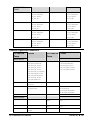
Opto
Formed by a LED emitter combined with a photo detector in close proximity, an opto-coupler (or
opto-isolator) allows for the connection between the PC2-CamLink external trigger and the user
circuitry using separate grounds. This ‘galvanic isolation’ prevents ground loops and protects both
circuits. A jumper-selectable resistor is connected in serial fashion to the opto-coupler to limit the
current.
Both opto-coupled triggers allow serial resistor selection that is used to limit the current flowing
through the diode. This is seen in the following tables.
OPTO1:
Jumper
Voltage Selection
Serial Resistor
J5
12V
1.33 KΩ
J6
5V
221Ω
Note: Only select jumper J5 or J6, not both simultaneously.
OPTO2:
Jumper
Voltage Selection
Serial Resistor
J3
12V
1.33 KΩ
J4
5V
221Ω
Note: Only select jumper J3 or J4, not both simultaneously.
PC2-CamLink User's Manual
Part I: PC2-CamLink Board • 29
3.3V
1.33k
(1W) J3: opto2
Opto2_Trig +
J4: opto2
221
(0.1W)
Opto2_Trig -
Opto-Coupler
3.3V
1.33k
Trigger
Controller
(1W) J5: opto1
Opto1_Trig +
J6: opto1
221
(0.1W)
Opto1_Trig -
Opto-Coupler
Figure 6: Opto-coupler
When current flows inside the LED, the emitted light acts as a base current for the transistor.
Depending on the amount of light that is being emitted, the transistor can be turned ON, just like a
switch. The information, in the form of a voltage, is transmitted from one side to the other as a
transistor being turned ON or OFF. The opto-coupled input is an inverting circuit; PC2-CamLink
software compensates for this when specifying the polarity.
The surrounding circuit that converts the voltage to current and into the LED is therefore crucial to the
performance of the opto-coupler. If the current flowing through the LED is too small, the emitted light
will not turn the transistor ON.
HPCL-0531 is the typical opto-coupler on the PC2-CamLink. It is designed for high-speed TTL/TTL
applications. A standard 16mA TTL sink current through the input LED will provide enough output
current for one TTL load. Maximum rates are given below:
Electrical
parameters
Description
Value
IF avg
Average forward input current
25mA
IF peak
Peak forward input current
50mA
VR
Reverse LED input voltage
5V
tpHL max
Maximum propagation delay from high to low
1.0μs
tpLH max
Maximum propagation delay from low to high
1.0μs
Note: TTL signals are approximately 0 and 5V corresponding to logical 0 and 1, respectively. A
standard TTL output can sink 16mA and could be used as a sink to drive an opto-coupled input. In
30 • Part I: PC2-CamLink Board
PC2-CamLink User's Manual
other words, +5V is connected to Ext_Trig+ and the sink trigger source is connected to Ext_Trig-.
This will normally require the application the invert the polarity of the trigger in the camera
configuration file.
Many TTL devices will not supply enough current to reliably drive the Ext_Trig+ of an opto-coupled
input; a buffer is needed between the TTL output and the Ext_Trig+ input. One possibility is a CMOS
buffer with TTL compatible inputs, such as the 74AC240 (inverting buffer) or 74AC241 (noninverting buffer). These devices can supply up to 24mA at close to the supply voltage. The other
alternative is to connect your TTL device to Ext_Trig- and connect a +5V pull-up to Ext_Trig+ as
mentioned above.
Pinout:
Positive side (anode)
Negative side (cathode)
Opto trigger 1
DB-15, pin 1
DB-15, pin 9
Opto trigger 2
DB-15, pin 2
DB-15, pin 10
LVDS
LVDS (Low Voltage Differential Signaling) uses low-voltage dual-wire systems running 180° apart.
This enables noise to travel at the same level, which in turn can get filtered out more easily and
effectively.
Two LVDS trigger inputs are available on PC2-CamLink (for a total of 4 pins). These inputs are
typically implemented using the National Semiconductor DS90LV028A LVDS line receiver or a
compatible device.
Pinout:
Positive line
Negative line
LVDS trigger 1
DB-15, pin 4
DB-15, pin 11
LVDS trigger 2
DB-15, pin 5
DB-15, pin 12
SW Trigger
A software trigger is available to programmatically control the trigger event. This is generated by a
function call from the application.
User Timer
The PC2-CamLink offers a user timer that can be used to fire a frame acquisition at a specified frame
rate. Note that the user timer is asynchronous to all input pins.
The user timer has a minimum frequency of 0.1Hz and a maximum frequency of 10kHz with a step
size of 0.1Hz.
PC2-CamLink User's Manual
Part I: PC2-CamLink Board • 31
Sapera Parameters for Area Scan Trigger:
CORACQ_PRM_EXT_TRIGGER_ENABLE = {
CORACQ_VAL_EXT_TRIGGER_OFF, CORACQ_VAL_EXT_TRIGGER_ON}
CORACQ_PRM_EXT_TRIGGER_DETECTION = {
CORACQ_VAL_RISING_EDGE, CORACQ_VAL_FALLING_EDGE,
CORACQ_VAL_ACTIVE_LOW, CORACQ_VAL_ACTIVE_HIGH}
CORACQ_PRM_EXT_TRIGGER_DURATION: Debounce duration
CORACQ_PRM_EXT_TRIGGER_FRAME_COUNT: Number of frames to acquire per
trigger
CORACQ_PRM_EXT_TRIGGER_LEVEL = { CORACQ_VAL_LEVEL_TTL,
CORACQ_VAL_LEVEL_LVDS}
CORACQ_PRM_EXT_TRIGGER_SOURCE = {0 for automatic (defaults to trigger
input 1) }
CORACQ_PRM_INT_FRAME_TRIGGER_ENABLE = {TRUE, FALSE}
CORACQ_PRM_INT_FRAME_TRIGGER_FREQ: Frequency of user timer
In CamExpert, the external trigger parameters are located under the ‘External Trigger
Parameters’ tab. The internal frame trigger parameters are located under the ‘Advanced
Control Parameters’ tab.
IFC
IFC Parameters for Area scan Trigger:
P_TRIGGER_ENABLE = {IFC_DISABLE, IFC_ENABLE}
P_TRIGGER_POLARITY = {IFC_FALLING_EDGE, IFC_RISING_EDGE,
IFC_POL_ACTIVE_HIGH, IFC_POL_ACTIVE_LOW}
P_GEN_SW_TRIGGER = {0, 1}
P_TRIGGER_DEBOUNCE: Debounce duration
P_FRAMES_PER_TRIGGER: Number of frames to acquire per trigger
CL2_FRAME_TRIG_SRC = {CL2_SOFT_FRAME_TRIG,
CL2_OPTO_FRAME_TRIG1, CL2_OPTO_FRAME_TRIG2,
CL2_LVDS_FRAME_TRIG1, CL2_LVDS_FRAME_TRIG2,
CL2_FREQ_FRAME_TRIG }
CL2_FRAME_TRIG_FREQ: Frequency of user timer trigger source
Linescan Triggers
External triggers allows line acquisition to be synchronized to external events. When acquiring a line
in External Trigger mode, the acquisition will not start until the PC2-CamLink receives a trigger
signal. Acquisition begins with the next valid line after the trigger.
Two trigger events, the shaft encoder or a user timer, can fire the EXSYNC and PRIN pulse generators
for linescan cameras.
Linescan acquisition relies on the concept of virtual frames to simplify transfer to the host. Basically, a
virtual frame is defined as a number of consecutive lines that are grouped together into a single host
buffer.
32 • Part I: PC2-CamLink Board
PC2-CamLink User's Manual
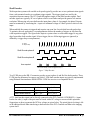
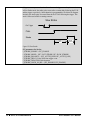
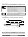
Shaft Encoder
Web inspection systems with variable web speeds typically provide one or two synchronization signals
from a web mounted encoder to coordinate trigger signals. The trigger signals are used by the
acquisition linescan camera. The PC2-CamLink supports single or dual shaft encoder signals. Dual
encoder signals are typically 90° out of phase relative to each other and provide greater web motion
resolution. When using only one shaft encoder input phase, phase A for example, the phase B inputs
must be terminated by connecting the + input to a minimum voltage of 100mV positive relative to the
input.
When enabled, the camera is triggered and acquires one scan line for each shaft encoder pulse edge.
To optimize the web application, a second parameter defines the number of triggers to skip between
valid acquisition triggers. The figure below depicts a system where a valid camera trigger is any pulse
edge from either shaft encoder signal. After a trigger, the two following triggers are ignored (as
defined by a trigger drop count parameter).
K = Keep
D = Drop or Skip
K
D
D
K
D
D
K
D
D
K
D
D
K
D
D
Shaft Encoder phase A
Shaft Encoder phase B
Line acquired
Note: in this example, number of triggers to drop = 2
Figure 7: Shaft Encoder
Two LVDS pins on the DB-15 connector provide access to phase A and B of the shaft encoder. These
LVDS pins are debounced to remove any glitch. LVDS shaft encoder inputs are typically implemented
using National Semiconductor DS90LV028A LVDS line receiver or a compatible device.
Pinout:
Positive line
Negative line
Shaft Encoder Phase A
DB-15, pin 6
DB-15, pin 13
Shaft Encoder Phase B
DB-15, pin 7
DB-15, pin 14
A TTL shaft encoder signal can be directly connected to the PC2-CamLink LVDS/RS422 (+) input,
but the low side (-) input of the pair must be biased with a DC voltage to ensure reliable operation.
Suggestions on how to generate the DC bias voltage are given below. The actual physical wiring is left
as an additional detail when interfacing a shaft encoder to the PC2-CamLink and then to the imaging
system itself.
PC2-CamLink User's Manual
Part I: PC2-CamLink Board • 33
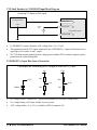
TTL Shaft Encoder to LVDS/RS422 Input Block Diagram
Connecting TTL Signals to LDVS Inputs
TTL signal source
LDVS (+) input
GND
LDVS (-) input
+1 to +2
volts
DC
Frame Grabber System
FG/system GND
•
LVDS/RS422 (-) input is biased to a DC voltage from +1 to +2 volts.
•
This guarantees that the TTL signal connected to the LVDS/RS422 (+) input will be detected as a
logic high or low relative to the (-) input.
•
The TTL shaft encoder ground, the bias voltage ground, and the PC2-CamLink computer system
ground must be connected together.
LVDS/RS422 (-) Input Bias Source Generation
3 Examples on Generating a DC voltage for the LDVS (-) Input
+5V
+1.5V
+12V
330
680
+2V
Battery
220
+1.5V
100
•
DC voltage for the LVDS/RS422 (-) input can be generated by a resister voltage divider.
•
Use a single battery cell if more suitable for your system.
•
A DC voltage (either +5 or +12) is available on DB-15 connector (J2).
34 • Part I: PC2-CamLink Board
PC2-CamLink User's Manual
User Timer
PC2-CamLink offers a user timer that can be used to fire a line acquisition at a specified frequency.
Note this user timer is asynchronous to all input pins.
The line rate generated by the user timer ranges from 1μs to 65535μs in steps of 1μs.
Virtual Frames Triggers
Virtual frame is a method grouping a number of consecutive lines from a linescan camera into a frame
buffer. This allows the application to manage host buffers using the same function calls independently
of the camera type (area or linescan).
Similar to area scan triggers, virtual frame triggers can use the opto-coupler trigger inputs, the LVDS
trigger inputs, or a SW trigger.
PC2-CamLink supports variable frame length, where a stop event indicates the end of the virtual frame
before the virtual frame buffer is filled. Note that if the stop event arrives after the virtual frame is
filled, this ‘late’ stop event will be discarded and the next virtual frame acquired during the next start
event. In variable frame length, the application specifies the largest virtual frame. This means that only
the first lines of the virtual frame buffer (up to the stop event) will be valid. Other lines will contain
the garbage that was already there before the start of acquisition.
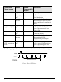
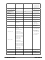
See the following table for the virtual frame trigger sources:
PC2-CamLink User's Manual
Part I: PC2-CamLink Board • 35
Virtual Frame
Trigger Source
Polarity
Variable
Frame Length
Support
Description
Software
not applicable
No
A whole virtual frame acquired on SW
trigger call
Opto1
rising or falling
edge
No
A whole virtual frame acquired on
Opto1 edge detection
Opto1
active high or
active low
Yes
Acquisition from the first edge up to
the second edge of Opto1. Acquisition
waits for next trigger if virtual frame is
filled.
Start pulse on Opto1,
stop pulse on Opto2
rising or falling
edge
Yes
Acquisition from the edge of Opto1 up
to the edge of Opto2. Acquisition
waits for next start trigger if virtual
frame is filled.
LVDS1
rising or falling
edge
No
A whole virtual frame acquired on
LVDS1 edge detection
LVDS1
active high or
active low
Yes
Acquisition from the first edge up to
the second edge of LVDS1.
Acquisition waits for next trigger if
virtual frame is filled.
Start pulse on
LVDS1, stop pulse on
LVDS2
rising or falling
edge
Yes
Acquisition from the edge of LVDS1
up to the edge of LVDS2. Acquisition
waits for next start trigger if virtual
frame is filled.
The following diagrams better illustrate the various modes of operation for virtual frame trigger:
TRIG
LVAL
VFVAL
Maximum virtual frame size
Figure 8: Edge or SW Trigger
36 • Part I: PC2-CamLink Board
PC2-CamLink User's Manual
Active high or active low trigger
TRIG
LVAL
VFVAL
Virtual frame size less than or equal to maximum
VFRAME size
Figure 9: Active High or Active Low Trigger
TRIG 1
TRIG 2
LVAL
VFVAL
VFRAME size less than or equal to maximum
VFRAME size
Figure 10: Start-Stop Trigger
Note: For virtual frame trigger, Opto1 and LVDS1 are always the start of a virtual frame trigger event,
while Opto2 and LVDS2 are always an end of a virtual frame trigger event.
Sapera Parameters for Virtual Frames Triggers:
CORACQ_PRM_EXT_FRAME_TRIGGER_ENABLE = {TRUE, FALSE}
CORACQ_PRM_EXT_FRAME_TRIGGER_DETECTION = {
CORACQ_VAL_RISING_EDGE, CORACQ_VAL_FALLING_EDGE,
CORACQ_VAL_ACTIVE_LOW, CORACQ_VAL_ACTIVE_HIGH,
CORACQ_VAL_DOUBLE_PULSE_RISING_EDGE,
CORACQ_VAL_DOUBLE_PULSE_FALLING_EDGE}
CORACQ_PRM_EXT_FRAME_TRIGGER_LEVEL = {
CORACQ_VAL_LEVEL_TTL, CORACQ_VAL_LEVEL_LVDS}
CORACQ_PRM_EXT_FRAME_TRIGGER_SOURCE = {0 for automatic (defaults to
trigger input 1 except for variable frame length with start-stop pulse where start pulse is
associated with trigger input 1 and stop pulse is associated with trigger input 2)}
CORACQ_PRM_EXT_TRIGGER_DURATION: Debounce duration
Sapera Parameters for Linescan triggers:
CORACQ_PRM_EXT_LINE_TRIGGER_ENABLE = {TRUE, FALSE}
CORACQ_PRM_EXT_LINE_TRIGGER_DETECTION =
CORACQ_VAL_RISING_EDGE
CORACQ_PRM_EXT_LINE_TRIGGER_LEVEL = CORACQ_VAL_LEVEL_LVDS
CORACQ_PRM_EXT_LINE_TRIGGER_SOURCE = {0 for automatic (both phases of
PC2-CamLink User's Manual
Part I: PC2-CamLink Board • 37
shaft encoder), 1 for phase A of shaft encoder}
CORACQ_PRM_LINE_TRIGGER_ENABLE = {TRUE, FALSE}
CORACQ_PRM_INT_LINE_TRIGGER_ENABLE = {TRUE, FALSE}
CORACQ_PRM_INT_LINE_TRIGGER_FREQ: User timer line frequency
Sapera Parameters for Shaft encoder:
CORACQ_PRM_SHAFT_ENCODER_ENABLE = {TRUE, FALSE}
CORACQ_PRM_SHAFT_ENCODER_LEVEL = CORACQ_VAL_LEVEL_LVDS
CORACQ_PRM_SHAFT_ENCODER_DROP: Number of shaft pulse to skip between
valid pulses
In CamExpert, these parameters are located under ‘Advanced Control Parameters’ for
line trigger selection, and under ‘External Trigger Parameters’ for external trigger and
shaft encoder configuration.
IFC
IFC Parameters for Virtual Frames Triggers:
P_VFRAME_TRIGGER_ENABLE = {IFC_DISABLE, IFC_ENABLE}
P_VFRAME_TRIGGER_POLARITY = {IFC_FALLING_EDGE, IFC_RISING_EDGE,
IFC_POL_ACTIVE_HIGH, IFC_POL_ACTIVE_LOW}
P_GEN_SW_TRIGGER = {0, 1}
P_VFRAME_TRIGGER_DEBOUNCE: Debounce duration
P_VFRAME_TRIG_SOURCE = {CL2_SOFT_TRIG, CL2_OPTO_VFRAME_TRIG1,
CL2_OPTO_VRAME_STARTTRIG1_STOPTRIG2, CL2_LVDS_VFRAME_TRIG1,
CL2_LVDS_VFRAME_STARTTRIG1_STOPTRIG2}
IFC Parameters for Linescan triggers:
CL2_LINE_TRIG_ENABLE = {IFC_DISABLE, IFC_ENABLE}
CL2_LINE_TRIG_SOURCE = {CL2_TIMER_LINE_TRIG,
CL2_SHAFT_LINE_TRIG}
CL2_LINE_TRIG_CYCLE_TIME: Timer interval for line trigger in
CL2_TIMER_LINE_TRIG
IFC Parameters for Shaft encoder:
CL2_LINE_TRIGGER_DROP_COUNT: Number of shaft pulse to skip between valid
pulses
CL2_LINE_TRIGGER_NUM_PHASE: Number of phase (1 or 2) of the shaft encoder
CL2_LINE_TRIGGER_TRIG_DEBOUNCE: Debounce duration
38 • Part I: PC2-CamLink Board
PC2-CamLink User's Manual
Strobe
One strobe signal is available on pin 15 of the DB-15 connector (J2). The pulse duration and polarity
are programmable (up to 65 seconds).
The strobe signal is attained by using an LVT244 driver with the following electrical characteristics:
Electrical
parameters
Description
Value
VOH typ
Typical high-level output voltage
3.1 V @ -100µA
IOH max
Maximum high-level output current
-32mA (sourcing)
IOL max
Maximum low-level output current
64mA (sinking)
Sapera Parameters for Strobe :
Refer to Strobe Method in the Sapera Acquisition Parameters Reference manual. Only
strobe method 1 is supported on PC2-CamLink.
CORACQ_PRM_STROBE_ENABLE = TRUE
CORACQ_PRM_STROBE_METHOD = CORACQ_VAL_STROBE_METHOD_1
CORACQ_PRM_STROBE_POLARITY = {CORACQ_VAL_ACTIVE_LOW
, CORACQ_VAL_ACTIVE_HIGH}
CORACQ_PRM_STROBE_DELAY: Pulse offset from trigger event
CORACQ_PRM_STROBE_DURATION: Pulse duration
CORACQ_PRM_STROBE_LEVEL = CORACQ_VAL_LEVEL_TTL
In CamExpert, these parameters are located under ‘Advanced Control Parameters’.
Select ‘Strobe Method Setting’.
IFC
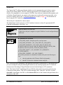
Under IFC, PC2-CamLink offers two types of strobes: Fast Strobe and Slow Strobe. Fast
Strobe occurs immediately after the trigger. See below for diagram. The first trigger
falling edge immediately generates a strobe pulse. The strobe pulse duration is
programmable. This mode is often used with asynchronous reset cameras.
Fast Strobe
Ext. Trigger
Strobe
Strobe
delay
Strobe
duration
Figure 11: Fast Strobe
Note: PC2-CamLink does not support an exclusion region in Fast Strobe mode. A strobe
PC2-CamLink User's Manual
Part I: PC2-CamLink Board • 39
delay parameter represents the time from the external trigger to strobe pulse assertion.
In Slow Strobe mode, the strobe pulse occurs after a certain delay following the FVAL
and the trigger, respectively. Strobe duration is programmable. See below for diagram.
Basically, the strobe pulse is asserted from the first FVAL following the trigger. This
mode is often used with free-running cameras.
Slow Strobe
Ext. Trigger
FVAL
Strobe
Strobe
delay
Strobe
duration
Figure 12: Slow Strobe
IFC parameters for Strobe :
P_STROBE_ENABLE = IFC_ENABLE
P_STROBE_MODE = {IFC_FAST_STROBE, IFC_SLOW_STROBE}
P_STROBE_POLARITY = {IFC_ACTIVE_HIGH, IFC_ACTIVE_LOW}
P_STROBE_DELAY: Pulse offset from trigger event
P_STROBE_DURATION: Pulse duration
P_STROBE_ALIGN_ON_HS = {IFC_DISABLE, IFC_ENABLE}
40 • Part I: PC2-CamLink Board
PC2-CamLink User's Manual
Serial Port
The Camera Link™ cabling specification includes a serial communication port for direct camera
control by the frame grabber. The PC2-CamLink supports this serial communication port either
directly or by mapping it to a host computer COM Port. Any serial port communication program, such
as Windows HyperTerminal, can connect to the camera in use and modify its function modes via its
serial port controls. Refer to the “Configuring Serial Port” section (on page 17) for information on
how to map the PC2-CamLink serial port as a COM Port.
This serial port is intended for camera control.
The default name for this serial port is: PC2-CamLink_X_Serial_0, where X represents the PC2CamLink board number, valid from 1 to 8.
Note: A typical configuration would use 9600 baud, 8-bit, no parity, 1 stop bit (9600-8-N-1).
Sapera parameters for Serial Port
In Sapera, the serial port is mapped as a regular COM Port. It can be configured through
WIN32 API.
IFC
IFC parameters for Serial Port
P_COM_PORT_NAME : String that specifies serial port name
P_COM_PORT_BYTESIZE = {IFC_COM_7BITS, IFC_COM_8BITS}
P_COM_PORT_BAUDRATE = {IFC_BAUD_4800, IFC_BAUD_9600,
IFC_BAUD_14400, IFC_BAUD_19200, IFC_BAUD_38400, IFC_BAUD_56000,
IFC_BAUD_57600, IFC_BAUD_115200, IFC_BAUD_128000}
P_COM_PORT_PARITY = {IFC_NOPARITY, IFC_ODDPARITY,
IFC_EVEN_PARITY}
P_COM_PORT_STOPBITS = {IFC_ONE_STOPBIT}
IFC uses those parameters to communicate with the serial port in the following two
cases:
•
when the application calls CICamera::WriteUartCommand().
•
when IFC uses the rule evaluation from the config file.
Note: The serial port is configured by the application that opens a connection to it. This means that if
you are accessing the serial port from HyperTerminal (or any similar program), the PC2-CamLink
serial port uses the settings of HyperTerminal, not ones from the Sapera or IFC parameters.
Note: The Camera Link™ standard specifies an API that can be used to access any serial port on a
CameraLink frame grabber. This API is available through a DLL. Under IFC, this DLL is called
clsercii.dll. Under Sapera, this DLL is called clsercor.dll. Refer to the Camera Link specification for a
description of this API.
PC2-CamLink User's Manual
Part I: PC2-CamLink Board • 41
Camera Interface
The PC2-CamLink supports the Camera Link™ specification base configuration (one connector, 24bit data) and clock rates up to 66 MHz. The Camera Link™ specification also defines medium and full
configurations with two and three connectors as well as a larger data size. The PC2-CamLink does not
support the medium and full configurations. All signal and timing characteristics match the Camera
Link™ specification.
•
The PC2-CamLink accepts up to 24-bit data in differential format.
•
The PC2-CamLink is assembled with Camera Link™ LVDS devices.
•
The PC2-CamLink supports camera data rates up to 66MHz.
•
The PC2-CamLink accepts single channel (8, 10, 12, 14, 16-bits) and Dual Channel (8, 10, 12bits).
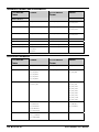
The Camera Link™ specification defines the 24-bit input as three bytes: Port A, Port B, and Port C.
Port A is the least significant byte (LSB) and Port C is the most significant byte (MSB). This
assignment is easily understood for 8-bit input. With single tap or single channel cameras, even 10, 12,
and 16-bit inputs are fairly simple. Confusion begins with the assignment of 10-bit and 12-bit 2-tap or
two channel cameras. The Data and Port Assignments Table below shows the data bit assignments for
all three ports.
Data and Port Assignments Table
Port/Bit
assignent 8-bit 1–2 10-bit 1
tap
tap
10-bit 2
taps
12-bit 1
tap
12-bit 2
taps
14-bit 1
tap
16-bit 1
tap
Port A
A0
A0
A0
A0
A0
A0
A0
A0
A1
A1
A1
A1
A1
A1
A1
A1
A2
A2
A2
A2
A2
A2
A2
A2
A3
A3
A3
A3
A3
A3
A3
A3
A4
A4
A4
A4
A4
A4
A4
A4
A5
A5
A5
A5
A5
A5
A5
A5
A6
A6
A6
A6
A6
A6
A6
A6
A7
A7
A7
A7
A7
A7
A7
A7
B0
B0
A8
A8
A8
A8
A8
A8
B1
B1
A9
A9
A9
A9
A9
A9
B2
B2
x
x
A10
A10
A10
A10
B3
B3
x
x
A11
A11
A11
A11
B4
B4
x
B8
x
B8
A12
A12
Port B
42 • Part I: PC2-CamLink Board
PC2-CamLink User's Manual
B5
B5
x
B9
x
B9
A13
A13
B6
B6
x
x
x
B10
x
A14
B7
B7
x
x
x
B11
x
A16
C0
x
x
B0
x
B0
x
x
C1
x
x
B1
x
B1
x
x
C2
x
x
B2
x
B2
x
x
C3
x
x
B3
x
B3
x
x
C4
x
x
B4
x
B4
x
x
C5
x
x
B5
x
B5
x
x
C6
x
x
B6
x
B6
x
x
C7
x
x
B7
x
B7
x
x
Port C
The PC2-CamLink supports area scan and linescan cameras:
•
Maximum image size up to 8K x 8K pixels for area scan.
•
Maximum image size up to 8K x 8K number of lines for linescan. Variable frame length for
linescan (level control or start/stop pulses).
Input LUT
A different LUT is assigned to all three Camera Link™ ports (port A, port B, and port C). The LUT
operates at the resolution of 8-bits in and 8-bits out. Note that it cannot operate on pixel sizes above 8bits. The LUT can be used for point transfers as well as thresholding.
Note: ILUT appears before the data port sequencer. In other words, pixels above 8-bits have not yet
been reformatted at that point. Therefore, the ILUT should not be used for cameras that have a pixel
depth above 8-bits. This is true even if 8-bit truncation is activated in the data port sequencer.
LUT
0
255
1
255
Input
2
255
1
3
255
Camera
Output Data Port
255
Sequencer
...
...
252
0
253
0
254
0
255
0
Figure 13: Lookup Table Example
PC2-CamLink User's Manual
Part I: PC2-CamLink Board • 43
Sapera parameters for Lookup Table:
CORACQ_PRM_LUT_ENABLE = {TRUE, FALSE}
CORACQ_PRM_LUT_FORMAT = CORACQ_VAL_OUTPUT_FORMAT_MONO8
CORACQ_PRM_LUT_MAX = 1
CORACQ_PRM_LUT_NENTRIES = 256
CORACQ_PRM_LUT_NUMBER = 0
Use CorAcqSetLut() to load a LUT into PC2-CamLink.
CamExpert does not provide direct access to these parameters. They must be
activated programmatically from your Sapera application through the SapLut
class.
IFC
IFC parameters for Lookup Table:
P_INPUT_LUT1_FILE: filename for LUT
Data Port Sequencer
Multi-channel area scan and linescan cameras output image data in a variety of pixel sequences. An
important PC2-CamLink feature is its ability to transfer images to the host in the normal raster scan
format for processing or display. Re-sequencing is performed in realtime without host processor
intervention. Typical multi-channel image re-sequencing consists of reordering odd and even pixel
sequences, odd or even lines, or segmented scans.
The PC2-CamLink Data Port Sequencer has the ability to promote 10-bit, 12-bit, and 14-bit pixels to
16-bits. It optionally supports truncation to 8-bits for all pixel depths above 8-bits.
The figures in this section illustrate a variety of multi-channel pixel data sequences from linescan and
area scan cameras. PC2-CamLink can re-sequence all situations shown.
Note: The PC2-CamLink only supports re-sequencing from left to right, and top to bottom. Any
channel configuration scanning from right to left, or from bottom to top is not directly supported and
must be re-sequenced by software on the host processor.
44 • Part I: PC2-CamLink Board
PC2-CamLink User's Manual
Single Channel
One channel presents the pixel data in sequential order. The acquired sequence represents the original
image, without need of sorting or reformatting. The figure below (single channel) shows where the
data appears in the original image. PC2-CamLink can support this format for pixel depths from 8-bit
up to 16-bit. The IFC Software Library calls this “One Channel Left to Right” or CL2_1CHAN_L2R.
A A A A A A
Single channel
Odd-Even Pixels
One channel (A) carries only the even pixels, the other (B) carries only odd. Data is presented
simultaneously on both channels. The pixels are “interleaved” in the original image. The figure below
(odd-even pixels) shows where the data appears in a line from the original image. PC2-CamLink can
support this format for pixel depths from 8-bits up to 12-bits. The IFC Software Library calls this
‘Two Channel Interleaved’ or CL2_2CHAN_INTERLEAVED.
A B A B A B
Odd-even pixels
Dual-Channel with Line Segments
One channel (A) carries the left half of the line or frame, the other (B) carries the right half of the line
or frame. Data is presented simultaneously on both channels. The figure below (two line segments)
shows where the data appears in a line from the original image. PC2-CamLink can support this format
for pixel depths from 8-bits up to 12-bits. The IFC Software Library calls this “Two Channel Separate
Tap Left to Right” or CL2_2CHAN_SEP_TAP_L2R.
A
B
Two line Segments
PC2-CamLink User's Manual
Part I: PC2-CamLink Board • 45
Dual-Channel Interline
One channel carries the even lines, the other the odd lines. The lines are ‘interlaced’ in the original
image. Data is presented simultaneously on both channels. The figure below (Interline) shows where
the data appears in the original image. There are two options, as shown in the figure below. Channel A
can present the even lines 0, 2, 4, 6, 8 or the odd lines 1, 3, 5, 7, 9. The PC2-CamLink can support this
format for pixel depths from 8-bits up to 12-bits. The IFC Software Library calls this “Two Tap
Interline A Even” and “Two Tap Interline B Even” or CL2_2TAP_INTERLINE_A_EVEN and
CL2_2TAP_INTERLINE_B_EVEN.
A Even
A
B
B Even
B
A
Interline
Sapera parameters for Data Port Sequencer Table:
CORACQ_PRM_TAPS = {1, 2}
CORACQ_PRM_TAP_OUTPUT = {
CORACQ_VAL_TAP_OUTPUT_SEGMENTED,
CORACQ_VAL_TAP_OUTPUT_ALTERNATE,
CORACQ_VAL_TAP_OUTPUT_PARALLEL}
CORACQ_PRM_TAP_1_DIRECTION = { CORACQ_VAL_TAP_DIRECTION_LR,
CORACQ_VAL_TAP_DIRECTION_UD,
CORACQ_VAL_TAP_DIRECTION_FROM_TOP}
CORACQ_PRM_TAP_2_DIRECTION = { CORACQ_VAL_TAP_DIRECTION_LR,
CORACQ_VAL_TAP_DIRECTION_UD,
CORACQ_VAL_TAP_DIRECTION_FROM_TOP}
CORACQ_PRM_CHANNEL = { CORACQ_VAL_CHANNEL_SINGLE,
CORACQ_VAL_CHANNEL_DUAL}
CORACQ_PRM_CHANNELS_ORDER = {
CORACQ_VAL_CHANNELS_ORDER_NORMAL,
CORACQ_VAL_CHANNELS_ORDER_REVERSE}
In CamExpert, these parameters are located under the “Basic Timing Parameters” tab.
Select “Camera Sensor Geometry Setting”.
46 • Part I: PC2-CamLink Board
PC2-CamLink User's Manual
IFC
IFC parameters for Data Port Sequencer Table:
CL2_IMAGE_GEOMETRY = {CL2_1CHAN_L2R, CL2_2CHAN_INTERLEAVED,
CL2_2CHAN_SEP_TAP_L2R, CL2_2TAP_INTERLINE_A_EVEN,
CL2_2TAP_INTERLINE_B_EVEN}
P_PIXEL_SIZE: pixel size of host buffer from 8 to 16 bits
P_CAM_PIXEL_SIZE: pixel size from camera, 0 if camera has same pixel size as host
buffer
P_PIXEL_COLOR = {IFC_MONO}
Window Generator
The Window Generator extracts a window from the incoming image. This window is represented by a
rectangle where the upper-left corner is set by horizontal and vertical offset from the start of valid
video and the rectangle size by width and height parameters. See diagram below. Note that image
widths must be a multiple of four bytes because of transfer restrictions on the PCI bus.
Window Generator
Complete frame
Vertical offset
Window
Horizontal offset
Height
Width
Figure 14: Window Generator
Window Generator operates after the channels have been recombined by the data port sequencer;
therefore, image width and height applies to this recombined image, not to individual channels.
PC2-CamLink User's Manual
Part I: PC2-CamLink Board • 47
Sapera Parameters for Cropper:
CORACQ_PRM_CROP_WIDTH: Horizontal width of area of interest
CORACQ_PRM_CROP_LEFT: Horizontal offset
CORACQ_PRM_CROP_HEIGHT: Vertical height of area of interest
CORACQ_PRM_CROP_TOP: Vertical offset
In CamExpert, these parameters are located under the ‘Image Buffer and AOI
Parameters’ tab.
IFC
IFC Parameters for Cropper:
P_HORZ_OFF: Horizontal offset
P_WIDTH_PIXELS: Horizontal width of area of interest
P_VERT_OFF: Vertical offset
P_HEIGHT_PIXELS: Vertical height of area of interest
Note: Under IFC, a special situation occurs for 2-channel segmented cameras. In this
case, Window Generator must know how many inactive pixels are present at the
beginning of each line (after the LVAL) in order to correctly extract a region of interest.
This is why this particular geometry requires two additional parameters to identify the
number of active and inactive pixels per channel.
P_HORZ_INACTIVE: Number of inactive pixel per channel after LVAL (only used in
2-channel segmented)
P_HORZ_ACTIVE: Number of active pixel per channel (only used in 2-channel
segmented)
YCrCb Engine
The YCrCb Engine converts an 8-bit monochrome image into a 16-bit padded YCrCb image to display
in overlay (Windows secondary surface). The value 0x80 is placed in chrominance by the YCrCb
Engine and is added during PCI transfer. Furthermore, the YCrCb Engine eliminates CPU
involvement when copying host buffers into display by transferring directly into overlay, bypassing
the CPU.
Note: The YCrCb Engine is only available for monochrome cameras. If your camera has a pixel depth
above 8-bits, pixel data will be first truncated to 8-bits.
Sapera Support for YCrCb Engine:
CORACQ_PRM_OUTPUT_FORMAT =
CORACQ_VAL_OUTPUT_FORMAT_YUY2
In CamExpert, this parameters is located under the ‘Image Buffer and AOI Parameters’
tab. Select ‘Image Buffer Format’.
48 • Part I: PC2-CamLink Board
PC2-CamLink User's Manual
IFC
IFC Support for YCrCb Engine:
Create an image connection using IfxCreateImgConn()with the flag
IFC_YCRCB_SINK or use IfxCreateImgSink() with the YCRCB_SINK flag.
PCI Controller
PCI controller has scatter-gather support to reduce CPU usage to a minimum. It retrieves a buffer
descriptor list from host memory. The PCI controller can sustain an average transfer rate up to
100MB/second with bursts of 132MB/second. Note that the PC2-CamLink provides a 4KB data FIFO
between the acquisition circuitry and the PCI controller. It does not have any onboard frame buffers.
Note: Achievable sustained transfer rates depend on how many PCI devices are trying to utilize bus
master on the PCI bus concurrently. For optimal performance while grabbing, ensure that the PC2CamLink is the only device utilizing the bus master on the PCI bus. Otherwise, if sufficient PCI
bandwidth is unavailable, a discarded frame can result.
PCI Bandwidth Discussion
Bandwidth is usually expressed in MB per seconds (MBps). The classic 32-bit PCI bus has a 32-bit
wide data bus, with a clock rate of 33.3MHz. The maximum theoretical transfer speed is 4bytes (32bit) * 33.3MHz = 133MB per second. However, since the PCI bus communication protocol introduces
overhead and that other devices are accessing the PCI bus, the practical capacity is generally around
60-80MB per second and is highly dependant upon your PCI chipset. In general:
1.
If the required bandwidth is smaller than 60MB per second, it should be acceptable for most
PC systems available on the marketplace today.
2.
If the required bandwidth has a range between 60MB per second to 80MB per second,
precaution must be considered towards the system’s chipset quality and towards other PCI
devices installed within the same system.
3.
Bandwidth larger than 80MB per second cannot reliably be handled by PC2-CamLink
because of its FIFO-based architecture. Consider using the DALSA PC-CamLink or X64-CL
in this case. These latter boards provide enough onboard memory to compensate for PCI
latencies.
Because the PC2-CamLink transfer engine is using a 4KB FIFO for transfers, when the PC2-CamLink
is acquiring and transferring an image simultaneously, the FIFO gets filled at the maximum speed
during one line period. If the line size is smaller than 4KB, the line blanking period will allow the
FIFO to be emptied. However, a line size larger than 4KB requires the availability of the PCI bus
when the frame grabber transfers an image. This leads to two different methods of bandwidth
computation required by a particular camera.
Note: The line bandwidth is the limiting factor for both area scan and linescan cameras since the
onboard FIFO is not large enough to store a whole image. Even for area scan cameras, you must
ensure that the line bandwidth being output by the camera fits within the PCI bus range.
PC2-CamLink User's Manual
Part I: PC2-CamLink Board • 49
Case 1: Line size below 4KB
If the camera line dimension is smaller than 4096Bytes, the average line bandwidth must be used to
evaluate if the camera’s bandwidth is acceptable for a FIFO-based frame grabber, such as the PC2CamLink.
Line size = nb pixel/ lines * Bpp
where Bpp is the number of bytes required to store each pixel. 8-bit pixels require 1 byte/pixel while
the pixel depth of 10, 12, 14 or 16-bit/pixel requires 2 bytes/pixel.
Subsequently, the average line bandwidth can be obtained by the following formula:
Average line bandwidth = nb pixel/ lines * Line rate (Hz) * Bpp
Example:
Camera Model: JAI CV-M4+
Resolution:
1380x1030
Line Frequency: 25.43KHz
Bpp :
10-bits/pixel = 2bytes/pixel
Average Line Bandwidth = 1380 pixels * 25430Hz * 2 Bytes/pixel = 70MBps
We can see that the line averaged bandwidth reaches 70MB per second. This is acceptable if the PC2CamLink gets installed in a system with a chipset of good quality.
Case 2: Line size higher than 4KB
When the camera line size exceeds 4KB, the peak bandwidth concept has to be used to compute the
camera bandwidth and once again see if it respects the PCI bus bandwidth capabilities:
Peak line bandwidth = PClk * nb data channel * Bpp
Example:
Camera Model: Dalsa P2-21-6144
Resolution:
6144 pixels
Pixel Clock:
40MHz
Nb Channel:
2
Bpp :
8 bit/pixel = 1 byte/pixel
Peak Line Bandwidth = 40MHz * 2 channels *1 Bpp= 80MBps
We see that the peak line bandwidth reaches 80MB per second. With this bandwidth, the system has to
maintain a transfer rate of 80MB per second to avoid loosing any information. PC2-CamLink can
sustain this rate with a good PCI chipset.
Note: When installing multiple PC2-CamLinks on the same PCI bus, the total 133MB per second
bandwidth gets split between the boards, resulting in a lower effective bandwidth per card.
50 • Part I: PC2-CamLink Board
PC2-CamLink User's Manual
Bandwidth Optimization
Pixel Depth Truncation
One of easiest techniques is to transfer only the eight most significant bits when the camera’s pixel
depth is higher than 8-bits. If this compromise is acceptable, this will result in half the bandwidth
required for the full pixel depth. PC2-CamLink has the ability to truncate the digital information to 8bits/pixel. Use the following method to enable this feature:
Under Sapera, set image buffer format to 8-bit:
CORACQ_PRM_PIXEL_DEPTH = 10, 12, 14 or 16 bits/pixel
CORACQ_PRM_OUTPUT_FORMAT =
CORACQ_VAL_OUTPUT_FORMAT_MONO8
In CamExpert, the pixel depth is available under the ‘Basic Timing Parameters’ tab.
Select ‘Pixel Depth’. The output format is available under the ‘Image Buffer and AOI
Parameters’. Select ‘Image Buffer Format’.
IFC
Under IFC:
1. Statically, in the Configfile, set the Cam Pixel Size parameter to the nominal pixel
size of the camera (10, 12, 14 or 16-bits/pixel) and then set Pixel Size to 8.
2. Dynamically, in an application, call CICamera->
SetAcqParam(P_CAM_PIXEL_SIZE, camPixelSize) where camPixelSize is the
nominal pixel size of the camera and call CICamera->SetAcqParam(P_ PIXEL_SIZE,
8).
Bus Master Devices on PCI Bus
Bandwidth improvements can be obtained by simply removing PCI devices that consume a lot of PCI
bus cycles because the device is often accessed or because the device driver is using a ‘polling’
mechanism for communication.
Moving the VGA card to the AGP bus is a major helping factor for PCI bus traffic alleviation.
Reducing the PCI Latency Timer
The PCI latency timer parameter is part of the PCI configuration space of any PCI device. It specifies
the number of clock cycles a device can continue on the PCI bus once it has been requested by another
device. Most motherboards offer a configurable parameter in the BIOS called the PCI Latency Timer,
the value is in the number of clocks (0 to 255). A lower value will assure a higher bandwidth to the
PC2-CamLink installed within the system since the PC2-CamLink driver increases the PCI latency
timer.
PC2-CamLink User's Manual
Part I: PC2-CamLink Board • 51
Visual Status LEDs
PC2-CamLink hosts two visual status LEDs on its PCI bracket. They are labeled ACQ (acquisition)
and TRIG (external trigger).
The ACQ LED indicates the status of the acquisition based on the signals going through the Camera
Link™ MDR-26 connector. Possible LED states are outlined in table below.
ACQ LED State
Acquisition State
OFF
Fatal card error
Static Red
Camera is not connected (no Pixel Clock detected)
Static Green
Camera is connected
Blinking Green Slow (2 Hz)
Activity on LineValid pin
Blinking Green Fast (15 Hz)
Grabbing
The TRIG LED represents the status of the selected external trigger pin. This is based on the signals
going through the DB-15 connector. The TRIG LED is also used to indicate an error condition.
Possible LED states are explained in table below.
TRIG LED State
Trigger State
OFF
No trigger detected
Blinking Green
Triggers at a slow rate detected (one blink per
trigger)
Static Green
Triggers at a fast rate detected
Blinking or Static Red
Error detected by PC2-CamLink driver
Note: A PC2-CamLink application must be running to select the external trigger source for the TRIG
LED to operate. For instance, if the current camera config file selects OPTO1 as the current external
trigger source, only pulses detected on the DB-15’s OPTO1 pin will light the TRIG LED.
52 • Part I: PC2-CamLink Board
PC2-CamLink User's Manual
Parallel I/O
PC2-CamLink provides digital I/O capability for controlling or monitoring external events. The digital
input and output lines, available on the 26-pin header located at the top of the board, can be cabled to a
25-pin D-Sub connector that occupies an open slot in the PC chassis. The functionality of the I/O port
is as follows:
IN(7-0)
Eight digital TTL input lines provide the capability to read these as either raw or latched (by
STROBE_I) inputs.
OUT(7-0)
Eight digital TTL output lines driven by a programmable register.
STROBE_I
Input strobe signal can be used to latch the 8-bit input data (if this mode is selected). The
polarity of STROBE_I is programmable.
STROBE_O
Output strobe signal is an output line under software control.
I/O_INT
Interrupt input line that can be used to generate an interrupt (programmable edge).
Refer to "J8: Parallel I/O 26-Pin Dual-Row Connector" on page 70 for the connector pinout
information.
The Parallel I/O is backward compatible with PC2-Vision and has the ability to provide power to an
external box: Two dedicated 5V 500mA power pins (with fuse protection) are available.
The Parallel I/O functions using LVT244 drivers with the following electrical characteristics. The
model is a 3.3V low-voltage TTL device that is 5V tolerant.
Electrical
parameters
Description
Value
VIH min
Minimum high-level input voltage
2V
VIL max
Maximum low-level input voltage
0.8V
VI max
Maximum input voltage
5.5V
IOH max
Maximum high-level output current
-32mA (sourcing)
IOL max
Maximum low-level output current
64mA (sinking)
PC2-CamLink User's Manual
Part I: PC2-CamLink Board • 53
Sapera support for Parallel I/O:
Access to Parallel I/O is achieved using members of the SapGio class. Refer to
Sapera++ Programmer’s manual for a complete description of the SapGio functions.
The resource indexes for the Parallel I/O are:
0: 8-bit output resource
1: 8-bit input resource
2: 1-bit interrupt resource
Example:
// Assert output pin 0 of Parallel I/O
m_pGioOutput = new SapGio(SapLocation("PC2-CamLink_1", 0));
m_pGioOutput->Create();
m_pGioOutput->SetPinConfig(dwBitScan, SapGio::PinOutput);
m_pGioOutput->SetPinState (0, SapGio::PinHigh);
Note: Sapera LT 5.0 does not support the input strobe and output strobe pins.
CamExpert does not provide direct access to the I/O. It must be activated
programmatically from your Sapera application using the SapGio class.
IFC
IFC Support for Parallel I/O:
Access to Parallel I/O is achieved using members of the CICapMod Class:
CICapMod::InportInterruptPolarity
CICapMod::InportMode
CICapMod::InportVal
CICapMod::OutportStrobeVal
CICapMod::OutportVal
54 • Part I: PC2-CamLink Board
PC2-CamLink User's Manual
Acquisition Interrupts
The PC2-CamLink provides acquisition interrupts that allow an application to monitor the acquisition
status accurately. This is one of the many elements that frame the “trigger-to-image reliability” model
supported by PC2-CamLink and its Acquisition and Control Unit (ACU).
These interrupts are grouped into four families representing each acquisition stage:
• Trigger Interrupt
• Start of Capture
• End of Capture
• End of PCI Transfer
The following block diagram illustrates the acquisition process and indicates at which stage each
interrupt occurs.
Trigger
Start of
Capture
Acq.
Engine
End of
Capture
FIFO
Memory
Camera
PCI
Controller
End of PCI transfer
Host
Memory
Figure 15: Acquisition Interrupts
IFC
Under IFC, an interrupt event object is created using the IfxCreateInterrupt() global
scope function. This returns a pointer to a CInterrupt object that is used to manage
interrupts. Refer to the IFC-SDK Software manual for more information using CInterrupt
objects.
PC2-CamLink User's Manual
Part I: PC2-CamLink Board • 55
Interrupt-Related Definitions
Interrupt
An interrupt is an electrical signal sent by the PC2-CamLink board to the
computer CPU to indicate an event on the frame grabber. The PC2-CamLink
driver has excellent reaction time to interrupts since interrupts are processed
inside an interrupt service routine (ISR) at kernel level.
Event
An event is a WIN32 object that can take two states: signaled and nonsignaled. It is used for thread synchronization. In this context, an event is
associated with an interrupt so that a WIN32 thread can be unblocked when
the event it is waiting for gets signaled. For example, when an interrupt is
received, the corresponding event is signaled and the thread waiting for this
event resumes execution.
Interrupt event
object
Under IFC, an interrupt object is an IFC virtualization of an event associated
to an interrupt.
Start of Trigger
The Start of Trigger interrupt is generated when the selected external trigger pin is asserted, usually
indicating the start of the acquisition process. In IFC, this is represented by CL2_INTR_SOT . In
Sapera, this is represented by CORACQ_VAL_EVENT_TYPE_EXTERNAL_TRIGGER.
PC2-CamLink is equipped with a debounce circuit that allows the user to define the minimum
acceptable pulse width programmatically.
Note: There is no Start of Trigger interrupt for a software trigger. This particular interrupt is only
asserted for a pulse on the selected external trigger pin.
Start of Capture
The Start of Capture interrupt family indicates a FVAL or LVAL has been detected. Note that this
does not necessarily mean the image will be captured. For instance, if you have a free-running camera
at 30fps with external trigger enabled, you will get 30 interrupts per second even though the PC2CamLink waits for an external trigger to actually capture the next image. This allows the application
program to count frames or lines coming from the camera.
Start of Frame
The Start of Frame interrupt represents the beginning of a full frame output by the camera. It is also
generated on the start of a virtual frame. It is asserted on the FVAL pulse (at the beginning of the
frame). In IFC, this is represented by CL2_INTR_VB . In Sapera, this is represented by
CORACQ_VAL_EVENT_TYPE_VERTICAL_SYNC.
56 • Part I: PC2-CamLink Board
PC2-CamLink User's Manual
Start/End of Line
For linescan cameras, the Start of Line interrupt represents the beginning of a valid line output by the
camera. It is asserted on the LVAL pulse (at the beginning of the line). This is represented by
CL2_INTR_HB in IFC.
Sapera offers the End of line interrupt through the
CORACQ_VAL_EVENT_TYPE_END_OF_NLINES event with N=1.
Warning: Start/End of Line interrupts occur at a very high rate. This may saturate your CPU and
prevent proper functioning of your OS. Make certain that your CPU is powerful enough to handle the
high interrupt rate generated by your area scan or linescan camera.
Note: For reasons of performance, each Start of Capture interrupt is only enabled if a user function has
been registered to process them.
End of Capture
The End of Capture interrupt family is asserted when capture is complete and data transferred to
onboard FIFO memory.
End of Frame
An End of Frame interrupt is generated when the last pixel from the image has been acquired and
transferred to onboard FIFO memory. It is also generated for virtual frames. This is represented by
CL2_INTR_EOFRM in IFC. In Sapera, this is represented by
CORXFER_VAL_EVENT_TYPE_END_OF_FRAME.
End of N Lines
For linescan cameras, the End of N Lines interrupt is generated when the last pixel from the Nth line
has been acquired and transferred to onboard FIFO memory. This is represented by
CL2_INTR_END_OF_NLINES in IFC. In Sapera, this is represented by
CORXFER_VAL_EVENT_TYPE_END_OF_NLINES.
PC2-CamLink User's Manual
Part I: PC2-CamLink Board • 57
End of PCI Transfer
The End of PCI Transfer interrupt is generated when each frame or virtual frame has been transferred
to host memory.
In Sapera, CORXFER_PRM_EVENT_TYPE provides the various transfer events.
The following are available on PC2-CamLink:
-CORXFER_VAL_EVENT_TYPE_END_OF_FRAME
-CORXFER_VAL_EVENT_TYPE_START_OF_FRAME
-CORXFER_VAL_EVENT_TYPE_END_OF_LINE
-CORXFER_VAL_EVENT_TYPE_END_OF_NLINES
-CORXFER_VAL_EVENT_TYPE_END_OF_TRANSFER
Under IFC, the end of transfer is represented by CL2_INTR_BMDONE .
IFC
Note: In IFC, most applications use the CICamera class GrabWaitFrameEx() member
function in order to wait for the end of transfer to host memory.
Timing Diagrams
The following diagram illustrates the exact location in time for each of the interrupts previously
described.
TRIG
FVAL
LVAL
1
2
3
4
5
1
2
3
4
5
1
2
3
Window
Generator
Interrupt
state of trigger
end of N lines (N = 5)
state of frame
end of N lines (N = 5)
end of frame + Bus Master Done
Note: 1 Start of line interrupt is not illustrated, but occurs on each rising edge of LVAL.
Note: 2 End of N lines interrupt illustrated for N = 5 lines.
Figure 16: Acquisition Interrupts
Note: The Bus Master Done interrupt location is dependant upon PCI bus traffic as well as the size of
the Window Generator. It, therefore, may occur after the FVAL of the next frame.
58 • Part I: PC2-CamLink Board
PC2-CamLink User's Manual
Error Support Interrupts
PC2-CamLink supports a number of interrupts generated when problematic conditions occur within
the system. These interrupts are used to notify applications that something erroneous occurred. Error
Support Interrupts are part of the “trigger-to-image reliability” support.
Skipped Frame
A Skipped Frame condition is signaled when the onboard FIFO is full resulting in the remainder of the
current acquired frame to be discarded. The buffer is marked full (since it might contain some of the
first pixels of the frame) and must be released by the application.
The TRIG LED blinks red to indicate an error condition when Skipped Frame occurs.
A typical cause of this problem is an insufficient PCI bandwidth. Maximal theoretical bandwidth of
the PCI bus is 132MB/second. If numerous bus master PCI devices are active simultaneously, a
possible shortage of bandwidth may affect the PC2-CamLink’s PCI controller.
Another possible cause could be a high-bandwidth camera. PC2-CamLink supports pixel clocks up to
66 MHz, with up to two channels and up to 12-bits per channel. The resulting bandwidth might easily
exceed the PCI maximum of 132MB/second. The Window Generator can be used as well as truncating
pixels to 8-bits to reduce the bandwidth.
Error on Pixel Clock
The Error on Pixel Clock condition is signaled when a pixel clock is not detected by PC2-CamLink. A
typical cause of this problem is when no camera has been connected to the MDR-26 Camera Link™
connector (J1).
The ACQ LED is solid red when this condition occurs.
Sapera provides the following events and status to handle error conditions on PC2CamLink:
-CORACQ_VAL_EVENT_TYPE_NO_PIXEL_CLK
-CORACQ_VAL_EVENT_TYPE_FRAME_LOST
-CORACQ_VAL_EVENT_TYPE_DATA_OVERFLOW
-CORBUFFER_VAL_STATE_OVERFLOW
To retrieve the buffer overflow indication, the application must call CorBufferGetPrm()
for the CORBUFFER_PRM_STATE parameter.
IFC
IFC provides the following interrupts to handle error conditions on PC2CamLink:
-CL2_INTR_FRAME_SKIPPED
-CL2_INTR_ERROR_PIXEL_CLOCK
PC2-CamLink User's Manual
Part I: PC2-CamLink Board • 59
Camera Power
PC2-CamLink can provide up to 1.5A of 5V or 12V power to the camera through the DB-15
connector.
The voltage supply is dependent on the configuration of jumper J13. Refer to "J13: Power to Camera
Voltage Selector" on page 71 for jumper settings.
The floppy power connector J14 must be connected if your camera requires more than 0.5A. That is, if
J14 is not connected, the PC2-CamLink will use power from the PCI connector to power the camera.
PCI specification limits the amount of power a card can take to 0.5A from the PCI connector.
Note: DALSA always recommends to connect the floppy power connector J14 when the PC2CamLink feeds power to the camera.
Caution: Drawing more than 500mA from the PC2-CamLink PCI connector may result in the autoreset fuse blowing or in erratic behavior of the camera, if the camera requires slightly more than
500mA. In this situation LED3 (Host 12V Overload) will light. Check your camera datasheet on how
much current is required.
Trigger-to-Image Reliability
Trigger-to-image reliability incorporates all stages of image acquisition inside an integrated controller
to increase reliability and simplify error recovery. The trigger-to-image reliability model fuses together
all the elements required to acquire images so that a central unit manages them coherently. These
elements include, among others, I/O to control timing to the camera and error notification. Whenever
PC2-CamLink detects a problem, the user application is immediately informed and can take
appropriate action to return to normal operation. PC2- CamLink offers this robustness through its
ACU (Acquisition and Control Unit), which manages the frame grabber input and monitors in real
time the acquisition state. As such, it is for the most part transparent to user applications.
On PC2- CamLink, user applications can interact with trigger-to-image reliability by means of the
following:
•
Glitches on the external trigger and shaft encoder lines are debounced by the ACU. A parameter is
available to indicate the minimal pulse duration to consider an external trigger pulse valid.
•
For each field, a number of interrupts are generated to indicate the following events:
• Trigger interrupt
• Start of capture interrupt
• End of capture interrupt
• End of transfer interrupt
•
By monitoring these events, it is possible to know the flow of acquisition of the system
•
If something goes wrong during the acquisition process, a notification is sent for the following:
• Skipped frame: Occurs when PCI bandwidth is limited or onboard FIFO is full. The
remaining data of the frame in the process of being acquired is discarded.
60 • Part I: PC2-CamLink Board
PC2-CamLink User's Manual
•
•
Error on Pixel Clock: No pixel clock detected from the camera.
Visual indicators on the PCI bracket give a clear indication of the acquisition and trigger status.
Additional LEDs are present at the back of the board, below the floppy power connector. These
LEDs indicate a camera power overflow.
The rest of trigger-to-image reliability is handled internally by the ACU to correctly synchronize
acquisition with camera control and image transfer. This is done automatically and does not require
user application involvement.
The following table summarizes trigger-to-image reliability features on the PC2-CamLink:
Features
Descriptions
Characteristics
Supported by
PC2-CamLink
Acquisition
Deterministic
Camera Control
Trigger input to strobe
output delay
EXSYNC Alignment
(digital)
Yes
Aligned to the first
occurrence of HD after
trigger input.
N/A
Aligned immediately
with trigger input
(instantaneous capture)
Yes
Double pulse integration
control on a single pin
Strobe alignment control
Yes
Aligned with the first
FVAL
Aligned with the
external trigger
Camera control timing
granularity
Yes
(IFC only)
Yes
1 microsecond
Maximum delay 64 msec
Maximum duration 64
msec
Yes
1 msec
Maximum delay 65
Seconds
Yes
Maximum duration 65
Seconds
Variable frame length
acquisition control
(linescan)
PC2-CamLink User's Manual
The ability to acquire
images of varying size.
Utilizes a start and stop
acquisition control
signal.
Yes
Part I: PC2-CamLink Board • 61
Yes,
Buffer data preventing
data corruption due to
PCI bus latency or
unavailability.
FIFO-based
(4 kilobytes)
Monitoring
Image Certificate
Visual Status LEDs
Events
(Certificate is encoded
by Sapera LT)
Camera not connected
Red
Yes
Camera detected, but not
operating within
established parameters.
Solid green
Yes
Camera detected and
operating correctly.
Flashing green
Yes
A valid trigger has been
detected
Valid trigger
Yes
Indicates if the soft-fuse
is open.
Camera power overload
Yes
Trigger event
Indicates that a trigger
occurred (object in
place).
Yes
Start of acquisition
Data is being acquired
from the camera.
Yes
End of acquisition
Acquisition is complete.
Yes
Start of transfer
Data is being transferred
to the host.
Yes
End of transfer
Data transfer is
complete.
Yes
An index or count of all
events (indicating if an
event has been missed).
Yes
Monitors the number of
pixels being acquired
from the camera.
Line length integrity
No
Monitors the number of
lines per frame acquired
from the camera.
Frame length integrity
Yes
Event index
Data Integrity
Yes
Unique image identifier
recorded along with the
image data. Can be used
to correlate physical
objects with images or to
ensure that the correct
sequence of images were
acquired.
62 • Part I: PC2-CamLink Board
(Sapera LT)
PC2-CamLink User's Manual
Reports that a camera is
connected with a valid
output
Yes
Trigger Debounce
Hardware rejection of
multiple short-lived
triggers. Minimum valid
trigger pulse duration is
SW programmable.
Yes
Invalid Trigger
Rejection
If two triggers are
detected in less than a
minimum time, the
second trigger is rejected
and an error event is
generated.
No
Circular Buffer
Management
Subsequent capture in
next empty buffer
Camera Presence
Recovery
Trash buffer if circular
list is full
Data Overrun
This condition occurs
when data becomes
corrupted during the
acquisition and transfer
process (An error event
is generated and the
frame is invalidated. The
next frame of data will
be acquired properly).
PC2-CamLink User's Manual
Yes
Yes
(Sapera LT)
Yes
Part I: PC2-CamLink Board • 63
Technical Reference
Block Diagram
26-Pin
Header
4
Data
CamLink
MDR-26
Base
Connector
Camera
Control
CamLink
Receiv er
4
Tx
Rx
In
Out
8
Strobe In
I/O
Controller
8
Strobe Out
Interrupt
ILUT
LVDS
UART
Image
Data
Acquisition
Visual Status
LED
Acquisition
Control Unit
PCI
Controller
LED
Trigger
Control
LED
Strobe
TTL Driv er
Trigger Opto #1
Trigger Opto #2
Trigger LVDS #1
Trigger LVDS #2
DB-15
Connector
Opto Coupler
Trigger
Controller
LVDSReceiv er
Shaf t Encoder #1
Shaf t Encoder #2
LVDS
Host ComputerPCI Bus
Not Connected
5V
(factorydefault)
+ Camera Power
32-bit / 33MHz
3.3V / 5V
12V
+ GND
Figure 17: Block Diagram
64 • Part I: PC2-CamLink Board
PC2-CamLink User's Manual
Hardware Specifications
The following provides detailed information related to PC2-CamLink hardware specifications.
PC2-CamLink Specifications
Function
Description
Board
PCI half-slot rev. 2.1 compliant for 5V and 3.3 V slots (32-bit, 33 MHz)
Acquisition
• 1 Base Camera
• Area scan and linescan
• 1 or 2 channels
Scanning
• 1-channel raster
• 2-channel interleaved pixels
• 2-channel interlines
• 2-channel half-line segmented (left to right)
Pixel Format
• 8, 10, 12, 14, 16-bit
• 10, 12, 14-bit pixels promoted to 16-bit
• 10, 12, 14, 16-bit pixels optionally truncated to 8-bit
• Pixel rate up to 66 MHz
Controls
• Support for EXSYNC and PRIN on any of the four Camera Control (CC) line
(SW selectable)
• 2 Trigger inputs SW selectable with debounce circuit (supports 2 Opto or 2
LVDS or 2 TTL)
• Quadrature shaft encoder (LVDS) with tick divider
• 1 Strobe TTL-level
Data Formatting
• 3x 8-bit ILUT
• Acquisition cropper
• YCrCb converter during PCI transfer
Image Size
• 8K pixel x 8K line for area scan
PC2-CamLink User's Manual
Part I: PC2-CamLink Board • 65
• 8K pixel x 8K # of lines for linescan
• Variable frame length for linescan (level control or 2 pulse controls)
PCI Transfer
• Up to 100MB/second sustained
Connectors
• One MDR-26 for Camera Link™
• One DB-15 for trigger, strobe and +12V/+5V power (available on PCI
bracket)
• One 26-pin header for Parallel I/O (flat cable to second slot)
I/O
• 19 general-purpose I/O pins, TTL level (8 input, 8 output, 2 strobes, 1
interrupt) with 2 soft-fused +5V power pins
• One RS-232C serial port, mapped as regular Windows COM PORT
Miscellaneous
• 2 Visual Status LED indicators: Acquisition and Trigger
Software
• Supported by Sapera LT, Sapera Processing, IFC™, MVTools, Sherlock,
WiT, VixN, Camera Configurator, Windows XP, Windows Vista, and Windows
7.
• Application development using Microsoft® Visual C/C++ DLLs or Visual
Basic
System
Requirements
• Intel® Pentium III® class CPU, 128MB system memory, 30MB free harddrive space
Dimensions
• 6.675” length x 4.2” height (standard PCI half-slot card)
Camera Power
• 5V (up to 1.5A) and 12V (up to 0.5A) taken from PCI connector with autoreset fuse
• Option to plug floppy power cable for more current (up to 1.5A)
Temperature
0○C (32○F) to 55○C (131○F)
Relative Humidity: 5% up to 95% (non-condensing)
66 • Part I: PC2-CamLink Board
PC2-CamLink User's Manual
PC2-CamLink Connector and Jumper Locations
PC2-CamLink Component View-revision A0
J13
J8
J14
LED 2
J11
J9
J1
LED 3
LED 4
PC2-CamLink
LED 1
LED 5
LED 6
J3
J4
J5
J2
J6
PCI Bus
Figure 18: Component View – revison A0
PC2-CamLink Component View-revision A1
J13
J8
J9
J1
J14
J11
LED 2
LED 3
PC2-CamLink
LED 1
LED 4
LED 5
LED 6
J3
J4
J5
J2
J6
PCI Bus
Figure 19: Component View – revison A1
Important: Revision A1 is different only in the orientation of J8. Pin one is on the upper right side of
the pin connector.
PC2-CamLink User's Manual
Part I: PC2-CamLink Board • 67
Connector Bracket
J2
LED
J1
ACQ
CAMERALINK
TRIG
Pin 1
Pin 1
Figure 20: Connector Bracket
J1: MDR 26-Pin Female Camera Connector
Pin 1
Pin 26
Pin #
Pin Name
Type
Description
25
BASE_X0-
Input
Neg. Base Data 0
12
BASE_X0+
Input
Pos. Base Data 0
24
BASE_X1-
Input
Neg. Base Data 1
11
BASE_X1+
Input
Pos. Base Data 1
23
BASE_X2-
Input
Neg. Base Data 2
10
BASE_X2+
Input
Pos. Base Data 2
21
BASE_X3-
Input
Neg. Base Data 3
8
BASE_X3+
Input
Pos. Base Data 3
22
BASE_XCLK-
Input
Neg. Base Clock
9
BASE_XCLK+
Input
Pos. Base Clock
20
SERTC-
Output
Neg. Serial Data to Camera
7
SERTC+
Output
Pos. Serial Data to Camera
19
SERTFG-
Input
Neg. Serial Data to Frame Grabber
6
SERTFG+
Input
Pos. Serial Data to Frame Grabber
18
CC1-
Output
Neg. Camera Control 1
5
CC1+
Output
Pos. Camera Control 1
17
CC2-
Output
Neg. Camera Control 2
4
CC2+
Output
Pos. Camera Control 2
16
CC3-
Output
Neg. Camera Control 3
3
CC3+
Output
Pos. Camera Control 3
15
CC4-
Output
Neg. Camera Control 4
2
CC4+
Output
Pos. Camera Control 4
1, 13, 14, 26
GND
68 • Part I: PC2-CamLink Board
Ground
PC2-CamLink User's Manual
J2: DB-15 Female Connector
Pin 1
Pin 15
Pin #
Pin Name
Type
1
Opto Trigger1+
Input
The anode’s side of the first opto-coupler. It can
manage up to 25V signals or TTL signals.
Configurable through a jumper.
9
Opto Trigger1-
Input
The cathode side of the first opto-coupler. It can
manage up to 25V signals or TTL signals.
Configurable through a jumper. Must be grounded
when in TTL mode.
2
Opto Trigger2+
Input
The anode side of the second opto-coupler. It can
manage up to 25V signals or TTL signals.
Configurable through a jumper.
10
Opto Trigger2-
4
LVDS Trigger1 +
Input
Positive line of first LVDS trigger signal.
11
LVDS Trigger1 -
Input
Negative line of first LVDS trigger signal.
5
LVDS Trigger2 +
Input
Positive line of second LVDS trigger signal.
12
LVDS Trigger2 -
Input
Negative line of second LVDS trigger signal.
6
Shaft Encoder ChA+
Input
Positive line of the shaft encoder channel A LVDS
signal.
13
Shaft Encoder ChA-
Input
Negative line of the shaft encoder channel A LVDS
signal.
7
Shaft Encoder ChB+
Input
Positive line of the shaft encoder channel B LVDS
signal.
14
Shaft Encoder ChB-
Input
Negative line of the shaft encoder channel B LVDS
signal.
15
Strobe
Output
8
12V/5V
3
GND
PC2-CamLink User's Manual
Description
The cathode side of the second opto-coupler. It can
manage up to 25V signals or TTL signals.
Configurable through a jumper. Must be grounded
when in TTL mode.
Strobe light output.
Jumper selectable camera power (1.5A maximum).
The power is provided by a floppy disk power
connector.
Ground
Part I: PC2-CamLink Board • 69
J3, J4, J5, J6: Opto-coupler Voltage Selector
The opto-coupler can be feed from 3V to 24V by means of jumper configuration. See diagram below
for jumper configuration selection.
J3
OPTO-2
J4
OR
OR
J5
OPTO-1
J6
unused
connect
0 to 6V
connect
6 to 25V
Figure 21: Opto-coupler Jumper Selection
J8: Parallel I/O 26-Pin Dual-Row Connector
Pin Identification as Viewed From Component Side
Board Revision A0
2
1
4
3
...
...
24
23
26
25
Board Revision A1
25
26
23
24
...
...
3
4
1
2
Header Pin #
Signal name
Description
Connector Pin #
1
GND
Digital ground
1
3
GND
Digital ground
2
5
GND
Digital ground
3
7
GND
Digital ground
4
9
IN1
Digital Input pin 1
5
11
IN3
Digital Input pin 3
6
13
IN5
Digital Input pin 5
7
15
IN7
Digital Input pin 7
8
17
OUT0
Digital Output pin 0
9
19
OUT2
Digital Output pin 2
10
21
OUT4
Digital Output pin 4
11
70 • Part I: PC2-CamLink Board
PC2-CamLink User's Manual
23
OUT6
Digital Output pin 6
12
25
+5V
+5V power output
13
2
STROBE_0
Strobe Output
14
4
STROBE_1
Strobe Input
15
6
I/O_INT
Interrupt Input
16
8
IN0
Digital Input pin 0
17
10
IN2
Digital Input pin 2
18
12
IN4
Digital Input pin 4
19
14
IN6
Digital Input pin 6
20
16
+5V
+5V power output
21
18
OUT1
Digital Output pin 1
22
20
OUT3
Digital Output pin 3
23
22
OUT5
Digital Output pin 5
24
24
OUT7
Digital Output pin 7
25
26
n/c
no connection
n/a
J9: Reserved
J11: Start Mode
•
•
Default Mode: Shunt jumper is installed.
Safe Mode: Shunt jumper is removed if any problems occurred while updating the PC2CamLink firmware. With the jumper off, reboot the computer and update the firmware
again. When the update is complete, install the jumper and reboot the computer once
again.
J13: Power to Camera Voltage Selector
When the PC floppy drive power supply cable is connected to J14, a shorting jumper on J13 selects
either no voltage, 5V, or 12V for the camera power supply. The voltage supply is dependent on jumper
configuration. See diagram below for J13 jumper configuration selection.
top board edge
top board edge
OR
connect
5V
top board edge
OR
connect
12V
no
voltage
Figure 22: Power to Camera Voltage Selector
PC2-CamLink User's Manual
Part I: PC2-CamLink Board • 71
J14: Power Connector
J14 must be connected to a computer floppy disk power cable to provide 12V or 5V to the camera
through the J2: DB-15 Female Connector.
To remove the floppy disk power cable from the J14 connector, carefully lift the cable connector head
from the J14 connector to unlatch the locking mechanism underneath the connector, then carefully pull
the cable from the board connector.
floppy disk
cable
J14
PC2-CamLink
locking
mechanism
carefully lift to unlock latch
and gently pull
Figure 23: Removing floppy power connector
LED
There are two light-emitting diodes on the front bracket (LED1). The top diode gives useful
information concerning the state of acquisition. The bottom diode gives useful information concerning
the state of the trigger. The following tables list the correspondence between the state of the top diode
and the state of acquisition and the bottom diode and the state of the trigger.
Acquisition LED State
Acquisition State
OFF
Fatal card error
Static Red
Camera is not connected (no Pixel Clock detected)
Static Green
Camera is connected
Blinking Green Slow (2 Hz)
Activity on LineValid pin
Blinking Green Fast (15 Hz)
Grabbing
Trigger LED State
Trigger State
OFF
No trigger detected
Blinking Green
Triggers at a slow rate detected (one blink per
trigger)
Static Green
Triggers at a fast rate detected
Blinking or Static Red
Error detected by PC2-CamLink driver
72 • Part I: PC2-CamLink Board
PC2-CamLink User's Manual
ACQ
Status: Camera Link Connector (J1)
Status: Trigger (J2)
TRIG
Figure 24: Visual Status LEDs
There are five additional LEDs located on the PC2-CamLink. These LEDs give supplemental
information concerning the state of the voltage supply, amp overload, and Safe Mode.
J14
LED 2
LED 3
LED 4
LED 5
LED 6
PC2-CamLink
Figure 25: Visual Status of Supplemental LEDs
The table below specifies each LED and the result of its activation.
Description
Result
LED2
1.5A Overload
Too much current drawn by the camera from the floppy connector.
LED3
Host 12V Overload
Too much current drawn by the camera from the PCI connector . Connect
power floppy cable.
LED4
Safe
Safe mode ON.
LED5
5V PCI
5 volts PCI bus detected.
LED6
3.3V PCI
3.3 volts PCI bus detected.
PC2-CamLink User's Manual
Part I: PC2-CamLink Board • 73
Computer Requirements for the PC2-CamLink
The PC2-CamLink requires at minimum an Intel Pentium III or compatible computer system with a
free PCI local bus slot.
Operating System Support
Windows XP, Windows Vista, and Windows 7.
PC2-CamLink Physical Dimensions
Approximately 6.675" length × 4.2" width (16.95 cm L×10.67 cm W) standard PCI half-slot card
Power Requirements
Typical
Maximum
+ 5 volts
3A
5A
+ 12 volts
120mA
250mA
- 12 volts
120mA
250mA
Environment
Ambient Temperature:
0° to 55° C (operation)
-40° to 125° C (storage)
Relative Humidity:
5% to 95% non-condensing (operating)
0% to 95% (storage)
74 • Part I: PC2-CamLink Board
PC2-CamLink User's Manual
Camera Link™ Interface
Camera Link™ Overview
Camera Link™ is a communication interface for vision applications developed as an extension of
National Semiconductor's Channel Link technology. The advantages of the Camera Link™ interface
are that it provides a standard digital camera connection specification, a standard data communication
protocol, and simpler cabling between camera and frame grabber.
The Camera Link™ interface simplifies the usage of increasingly diverse cameras and high signal
speeds without complex custom cabling. For additional information concerning Camera Link™, see
http://en.wikipedia.org/wiki/Camera_Link.
Rights and Trademarks
Note: The following text is extracted from the Camera Link Specification 1.1 (January 2004).
The Automated Imaging Association (AIA), as sponsor of the Camera Link committee, owns
the U.S. trademark registration for the Camera Link logo as a certification mark for the mutual
benefit of the industry. The AIA will issue a license to any company, member or non-member,
to use the Camera Link logo with any products that the company will self-certify to be
compliant with the Camera Link standard. Licensed users of the Camera Link logo will not be
required to credit the AIA with ownership of the registered mark.
•
•
•
•
3M™ is a trademark of the 3M Company.
Channel Link™ is a trademark of National Semiconductor.
Flatlink™ is a trademark of Texas Instruments.
Panel Link™ is a trademark of Silicon Image.
PC2-CamLink User's Manual
Part I: PC2-CamLink Board • 75
Data Port Summary
The Camera Link™ interface has three configurations. A single Camera Link™ connection is limited
to 28-bits requiring some cameras to have multiple connections or channels. The naming conventions
for the three configurations are:
• Base: Single Channel Link interface, single cable connector.
• Medium:
Two Channel Link interface, two cable connectors.
• Full:
Three Channel Link interface, two cable connectors.
Data Port Configuration Table
A single Camera Link™ port is defined as having an 8-bit data word. The "Full" specification supports
eight ports labeled as A to H.
Configuration
Ports Supported
PC2-CamLink Connector Used
Base
A, B, C
J1
Medium
A, B, C, D, E, F
J1 & J2
Full
A, B, C, D, E, F, G, H
J1 & J2
Camera Signal Summary
Video Data
Four enable signals are defined as:
• FVAL
Frame Valid (FVAL) is defined HIGH for valid lines.
• LVAL
Line Valid (LVAL) is defined HIGH for valid pixels.
• DVAL
Data Valid (DVAL) is defined HIGH when data is valid.
• Spare
A spare has been defined for future use.
All four enable signals must be provided by the camera on each Channel Link. All unused data bits
must be tied to a known value by the camera.
76 • Part I: PC2-CamLink Board
PC2-CamLink User's Manual
Camera Controls
Four LVDS pairs are reserved for general-purpose camera control, defined as camera inputs and frame
grabber outputs.
• Camera Control 1 (CC1)
• Camera Control 2 (CC2)
• Camera Control 3 (CC3)
• Camera Control 4 (CC4)
Note: the PC2-CamLink by default implements the control lines as follows
(using DALSA Corporation terminology).
(CC1) EXSYNC
(CC2) PRIN
(CC3) Low voltage
(CC4) Low voltage
Communication
Two LVDS pairs have been allocated for asynchronous serial communication to and from the camera
and frame grabber. Cameras and frame grabbers should support at least 9600 baud.
• SerTFG
Differential pair with serial communications to the frame grabber.
• SerTC
Differential pair with serial communications to the camera.
The serial interface protocol is 1 start bit, 1 stop bit, no parity, and no handshaking.
Camera Link™ Cables
For additional information on Camera Link™ cables and their specifications visit the following web
sites:
3M
http://www.3m.com/interconnects
(enter Camera Link as the search keyword)
Nortech Systems
http://www.nortechsys.com/intercon/CameraLinkMain.htm
PC2-CamLink User's Manual
Part I: PC2-CamLink Board • 77
78 • Part I: PC2-CamLink Board
PC2-CamLink User's Manual
Part II: Sapera LT
PC2-CamLink User's Manual
Part II: Sapera LT • 79
80 • Part II: Sapera LT
PC2-CamLink User's Manual
Sapera Server and Parameters
The following table lists the Sapera Server available for PC2-CamLink.
Servers
Name
PC2-CamLink_1
Resources
Description
Type
PC2-CamLink
Acquisition
Name
Index
Mono #1
0
Description
CameraLink Base Mono #1
The following four tables describe Sapera parameters and values supported by PC2-CamLink. Refer to
Sapera Acquisition Parameters Reference manual for a thorough description of each parameter.
CAMERA PARAMETERS
Values
CORACQ_PRM_CAM_LINE_TRIGGER_FREQ_MAX
16777215 Hz
CORACQ_PRM_CAM_LINE_TRIGGER_FREQ_MIN
1 Hz
CORACQ_PRM_CAM_NAME
Default Area Scan
CORACQ_PRM_CAM_RESET_DURATION
min = 1 µs
max = 65535000 µs
step = 1 µs
CORACQ_PRM_CAM_RESET_METHOD
CORACQ_PRM_CAM_RESET_POLARITY
CORACQ_VAL_CAM_RESET_METHOD_1 (0x1)
CORACQ_VAL_ACTIVE_LOW (0x1)
CORACQ_VAL_ACTIVE_HIGH (0x2)
CORACQ_PRM_CAM_TIME_INTEGRATE_DURATION_MAX
65535000 µs
CORACQ_PRM_CAM_TIME_INTEGRATE_DURATION_MIN
1 µs
CORACQ_PRM_CAM_TRIGGER_DURATION
min = 1 µs
max = 65535000 µs
step = 1 µs
CORACQ_PRM_CAM_TRIGGER_METHOD
CORACQ_VAL_CAM_TRIGGER_METHOD_1
(0x1)
CORACQ_VAL_CAM_TRIGGER_METHOD_2
(0x2)
CORACQ_PRM_CAM_TRIGGER_POLARITY
CORACQ_VAL_ACTIVE_LOW (0x1)
CORACQ_VAL_ACTIVE_HIGH (0x2)
CORACQ_PRM_CAMLINK_CONFIGURATION
CORACQ_VAL_CAMLINK_CONFIGURATION_
BASE (0x1)
CORACQ_PRM_CHANNEL
CORACQ_VAL_CHANNEL_SINGLE (0x1)
CORACQ_VAL_CHANNEL_DUAL (0x2)
PC2-CamLink User's Manual
Part II: Sapera LT • 81
CORACQ_PRM_CHANNELS_ORDER
CORACQ_VAL_CHANNELS_ORDER_NORMAL
(0x1)
CORACQ_VAL_CHANNELS_ORDER_REVERSE
(0x2)
CORACQ_PRM_CONNECTOR_EXPOSURE_INPUT
Default = 0
CORACQ_PRM_CONNECTOR_HD_INPUT
Default = 0
CORACQ_PRM_CONNECTOR_LINE_INTEGRATE_INPUT
Default = 0
CORACQ_PRM_CONNECTOR_LINE_TRIGGER_INPUT
Default = 0
CORACQ_PRM_CONNECTOR_LINESCAN_DIRECTION_INPUT
Default = 0
CORACQ_PRM_CONNECTOR_PIXEL_CLK_OUTPUT
Default = 0
CORACQ_PRM_CONNECTOR_RESET_TRIGGER_INPUT
Default = 0
CORACQ_PRM_CONNECTOR_VD_INPUT
Default = 0
CORACQ_PRM_CONNECTOR_WEN_OUTPUT
Default = 0
CORACQ_PRM_COUPLING
Not available
CORACQ_PRM_DATA_VALID_ENABLE
TRUE
CORACQ_PRM_DATA_VALID_POLARITY
CORACQ_VAL_ACTIVE_HIGH (0x2)
CORACQ_PRM_DETECT_HACTIVE
Not available
CORACQ_PRM_DETECT_PIXEL_CLK
Not available
CORACQ_PRM_DETECT_VACTIVE
Not available
CORACQ_PRM_FIELD_ORDER
CORACQ_VAL_FIELD_ORDER_NEXT_FIELD
(0x4)
CORACQ_PRM_FRAME
CORACQ_VAL_FRAME_PROGRESSIVE (0x2)
CORACQ_PRM_FRAME_INTEGRATE_METHOD
Not available
CORACQ_PRM_FRAME_INTEGRATE_POLARITY
Not available
CORACQ_PRM_HACTIVE
min = 16 pixels
FALSE
max = 8192 pixels
step = 4 pixels
CORACQ_PRM_HBACK_INVALID
min = 0 pixel
max = 16777215 pixels
step = 1 pixel
CORACQ_PRM_HBACK_PORCH
Not available
CORACQ_PRM_HFRONT_INVALID
min = 0 pixel
max = 16777215 pixels
step = 1 pixel
CORACQ_PRM_HFRONT_PORCH
Not available
CORACQ_PRM_HSYNC
min = 8 pixels
max = 4294967295 pixels
step = 1 pixel
CORACQ_PRM_HSYNC_POLARITY
CORACQ_VAL_ACTIVE_LOW (0x1)
CORACQ_PRM_INTERFACE
CORACQ_VAL_INTERFACE_DIGITAL (0x2)
82 • Part II: Sapera LT
PC2-CamLink User's Manual
CORACQ_PRM_LINE_INTEGRATE_METHOD
CORACQ_VAL_LINE_INTEGRATE_METHOD_1
(0x1)
CORACQ_VAL_LINE_INTEGRATE_METHOD_3
(0x4)
CORACQ_VAL_LINE_INTEGRATE_METHOD_4
(0x8)
CORACQ_PRM_LINE_INTEGRATE_PULSE0_DELAY
min = 0 µs
max = 65535000 µs
step = 1 µs
CORACQ_PRM_LINE_INTEGRATE_PULSE0_DURATION
min = 1 µs
max = 65535000 µs
step = 1 µs
CORACQ_PRM_LINE_INTEGRATE_PULSE0_POLARITY
CORACQ_VAL_ACTIVE_LOW (0x1)
CORACQ_VAL_ACTIVE_HIGH (0x2)
CORACQ_PRM_LINE_INTEGRATE_PULSE1_DELAY
min = 0 µs
max = 65535000 µs
step = 1 µs
CORACQ_PRM_LINE_INTEGRATE_PULSE1_DURATION
min = 1 µs
max = 65535000 µs
step = 1 µs
CORACQ_PRM_LINE_INTEGRATE_PULSE1_POLARITY
CORACQ_VAL_ACTIVE_LOW (0x1)
CORACQ_VAL_ACTIVE_HIGH (0x2)
CORACQ_PRM_LINE_TRIGGER_DELAY
min = 0 µs
max = 65535000 µs
step = 1 µs
CORACQ_PRM_LINE_TRIGGER_DURATION
min = 1 µs
max = 65535000 µs
step = 1 µs
CORACQ_PRM_LINE_TRIGGER_METHOD
CORACQ_VAL_LINE_TRIGGER_METHOD_1
(0x1)
CORACQ_PRM_LINE_TRIGGER_POLARITY
CORACQ_VAL_ACTIVE_LOW (0x1)
CORACQ_VAL_ACTIVE_HIGH (0x2)
CORACQ_PRM_LINESCAN_DIRECTION
Default = 0
CORACQ_PRM_LINESCAN_DIRECTION_POLARITY
CORACQ_VAL_ACTIVE_LOW (0x1)
CORACQ_VAL_ACTIVE_HIGH (0x2)
CORACQ_PRM_PIXEL_CLK_11
20000000 Hz
CORACQ_PRM_PIXEL_CLK_DETECTION
CORACQ_VAL_RISING_EDGE (0x4)
CORACQ_PRM_PIXEL_CLK_EXT
min = 20000000 Hz
max = 66000000 Hz
step = 1 Hz
CORACQ_PRM_PIXEL_CLK_INT
min = 20000000 Hz
max = 66000000 Hz
step = 1 Hz
PC2-CamLink User's Manual
Part II: Sapera LT • 83
CORACQ_PRM_PIXEL_CLK_SRC
CORACQ_VAL_PIXEL_CLK_SRC_EXT (0x2)
CORACQ_PRM_PIXEL_DEPTH
8 bits
10 bits
12 bits
14 bits
16 bits
CORACQ_PRM_SCAN
CORACQ_VAL_SCAN_AREA (0x1)
CORACQ_VAL_SCAN_LINE (0x2)
CORACQ_PRM_SIGNAL
CORACQ_VAL_SIGNAL_DIFFERENTIAL (0x2)
CORACQ_PRM_SYNC
CORACQ_VAL_SYNC_SEP_SYNC (0x4)
CORACQ_PRM_TAP_1_DIRECTION
CORACQ_VAL_TAP_DIRECTION_LR (0x1)
CORACQ_VAL_TAP_DIRECTION_UD (0x4)
CORACQ_VAL_TAP_DIRECTION_FROM_TOP
(0x10)
CORACQ_PRM_TAP_2_DIRECTION
CORACQ_VAL_TAP_DIRECTION_LR (0x1)
CORACQ_VAL_TAP_DIRECTION_UD (0x4)
CORACQ_VAL_TAP_DIRECTION_FROM_TOP
(0x10)
CORACQ_PRM_TAP_OUTPUT
CORACQ_VAL_TAP_OUTPUT_ALTERNATE
(0x1)
CORACQ_VAL_TAP_OUTPUT_SEGMENTED
(0x2)
CORACQ_VAL_TAP_OUTPUT_PARALLEL (0x4)
CORACQ_PRM_TAPS
min = 1 tap
max = 2 taps
step = 1 tap
CORACQ_PRM_TIME_INTEGRATE_METHOD
CORACQ_VAL_TIME_INTEGRATE_METHOD_1
(0x1)
CORACQ_VAL_TIME_INTEGRATE_METHOD_2
(0x2)
CORACQ_VAL_TIME_INTEGRATE_METHOD_3
(0x4)
CORACQ_VAL_TIME_INTEGRATE_METHOD_4
(0x8)
CORACQ_VAL_TIME_INTEGRATE_METHOD_5
(0x10)
CORACQ_VAL_TIME_INTEGRATE_METHOD_6
(0x20)
CORACQ_PRM_TIME_INTEGRATE_PULSE0_DELAY
min = 0 µs
max = 65535000 µs
step = 1 µs
CORACQ_PRM_TIME_INTEGRATE_PULSE0_DURATION
min = 1 µs
max = 65535000 µs
step = 1 µs
84 • Part II: Sapera LT
PC2-CamLink User's Manual
CORACQ_PRM_TIME_INTEGRATE_PULSE0_POLARITY
CORACQ_VAL_ACTIVE_LOW (0x1)
CORACQ_VAL_ACTIVE_HIGH (0x2)
CORACQ_PRM_TIME_INTEGRATE_PULSE1_DELAY
min = 0 µs
max = 65535000 µs
step = 1 µs
CORACQ_PRM_TIME_INTEGRATE_PULSE1_DURATION
min = 1 µs
max = 65535000 µs
step = 1 µs
CORACQ_PRM_TIME_INTEGRATE_PULSE1_POLARITY
CORACQ_VAL_ACTIVE_LOW (0x1)
CORACQ_VAL_ACTIVE_HIGH (0x2)
CORACQ_PRM_VACTIVE
min = 1 line
max = 8192 lines
step = 1 line
CORACQ_PRM_VBACK_INVALID
min = 0 line
max = 16777215 lines
step = 1 line
CORACQ_PRM_VBACK_PORCH
Not available
CORACQ_PRM_VFRONT_INVALID
min = 0 line
max = 16777215 lines
step = 1 line
CORACQ_PRM_VFRONT_PORCH
Not available
CORACQ_PRM_VIDEO
CORACQ_VAL_VIDEO_MONO (0x1)
CORACQ_PRM_VIDEO_LEVEL_MAX
Default = 0 µV
CORACQ_PRM_VIDEO_LEVEL_MIN
Default = 0 µV
CORACQ_PRM_VIDEO_STD
CORACQ_VAL_VIDEO_STD_NON_STD (0x1)
CORACQ_PRM_VSYNC
min = 0 line
max = 4294967295 lines
step = 1 line
CORACQ_PRM_VSYNC_POLARITY
CORACQ_VAL_ACTIVE_LOW (0x1)
CORACQ_PRM_VSYNC_TIMEOUT
Not available
CORACQ_PRM_WEN_POLARITY
Not available
PC2-CamLink User's Manual
Part II: Sapera LT • 85
VIC PARAMETERS
Values
CORACQ_PRM_BIT_ORDERING
CORACQ_VAL_BIT_ORDERING_STD (0x1)
CORACQ_PRM_BRIGHTNESS
Not available
CORACQ_PRM_BRIGHTNESS_BLUE
Not available
CORACQ_PRM_BRIGHTNESS_RED
Not available
CORACQ_PRM_CAM_RESET_DELAY
min = 0 µs
max = 65535000 µs
step = 1 µs
CORACQ_PRM_CAM_RESET_ENABLE
TRUE
FALSE
CORACQ_PRM_CAM_TRIGGER_DELAY
min = 0 µs
max = 65535000 µs
step = 1 µs
CORACQ_PRM_CAM_TRIGGER_ENABLE
TRUE
FALSE
CORACQ_PRM_CAMSEL
CAMSEL_MONO = from 0 to 0
CAMSEL_COLOR not available
CAMSEL_YC not available
CAMSEL_RGB not available
CORACQ_PRM_CONTRAST
Not available
CORACQ_PRM_CONTRAST_BLUE
Not available
CORACQ_PRM_CONTRAST_GREEN
Not available
CORACQ_PRM_CONTRAST_RED
Not available
CORACQ_PRM_CROP_HEIGHT
min = 1 line
max = 16384 lines for 2 channels, 8192 for 1 channel
step = 1 line
CORACQ_PRM_CROP_LEFT
min = 0 pixel
max = 16384 pixels for 2 taps, 8192 for 1 tap
step = 1 pixel
CORACQ_PRM_CROP_TOP
min = 0 line
max = 16384 lines for 2 channels, 8192 for 1 channel
step = 1 line
CORACQ_PRM_CROP_WIDTH
min = 16 pixels
max = 16384 pixels for 2 taps, 8192 for 1 tap
step = 4 pixels
CORACQ_PRM_DC_REST_MODE
CORACQ_VAL_DC_REST_MODE_AUTO (0x1)
CORACQ_PRM_DC_REST_START
Not available
CORACQ_PRM_DC_REST_WIDTH
Not available
CORACQ_PRM_DECIMATE_COUNT
Default = 0
CORACQ_PRM_DECIMATE_METHOD
CORACQ_VAL_DECIMATE_DISABLE (0x1)
86 • Part II: Sapera LT
PC2-CamLink User's Manual
CORACQ_PRM_EXT_FRAME_TRIGGER_DETECTION
CORACQ_VAL_ACTIVE_LOW (0x1)
CORACQ_VAL_ACTIVE_HIGH (0x2)
CORACQ_VAL_RISING_EDGE (0x4)
CORACQ_VAL_FALLING_EDGE (0x8)
CORACQ_VAL_DOUBLE_PULSE_RISING_EDGE (0x20)
CORACQ_VAL_DOUBLE_PULSE_FALLING_EDGE (0x40)
CORACQ_PRM_EXT_FRAME_TRIGGER_ENABLE
TRUE
FALSE
CORACQ_PRM_EXT_FRAME_TRIGGER_LEVEL
CORACQ_VAL_LEVEL_TTL (0x1)
CORACQ_PRM_EXT_FRAME_TRIGGER_SOURCE
0: automatic (always trigger input 1, except in variable frame length
where start pulse is associated with trigger input 1 and stop pulse is
associated with pulse 2)
CORACQ_PRM_EXT_LINE_TRIGGER_DETECTION
CORACQ_VAL_RISING_EDGE (0x4)
CORACQ_PRM_EXT_LINE_TRIGGER_ENABLE
TRUE
CORACQ_VAL_LEVEL_LVDS (0x4)
FALSE
CORACQ_PRM_EXT_LINE_TRIGGER_LEVEL
CORACQ_VAL_LEVEL_LVDS (0x4)
CORACQ_PRM_EXT_LINE_TRIGGER_SOURCE
0: Use phase A and B of shaft encoder input
1: Use phase A only of shaft encoder input
CORACQ_PRM_EXT_TRIGGER_DETECTION
CORACQ_VAL_ACTIVE_LOW (0x1)
CORACQ_VAL_ACTIVE_HIGH (0x2)
CORACQ_VAL_RISING_EDGE (0x4)
CORACQ_VAL_FALLING_EDGE (0x8)
CORACQ_PRM_EXT_TRIGGER_DURATION
min = 0 µs
max = 255 µs
step = 1 µs
CORACQ_PRM_EXT_TRIGGER_ENABLE
CORACQ_VAL_EXT_TRIGGER_OFF (0x1)
CORACQ_VAL_EXT_TRIGGER_ON (0x8)
CORACQ_PRM_EXT_TRIGGER_FRAME_COUNT
Default = 1 frame
CORACQ_PRM_EXT_TRIGGER_LEVEL
CORACQ_VAL_LEVEL_TTL (0x1)
CORACQ_PRM_EXT_TRIGGER_SOURCE
0: default (always trigger input 1)
CORACQ_PRM_FIX_FILTER_ENABLE
Not available
CORACQ_PRM_FIX_FILTER_SELECTOR
Not available
CORACQ_PRM_FLIP
Not available
CORACQ_PRM_FRAME_INTEGRATE_COUNT
Not available
CORACQ_VAL_LEVEL_LVDS (0x4)
CORACQ_PRM_FRAME_INTEGRATE_ENABLE
Not available
CORACQ_PRM_FRAME_LENGTH
CORACQ_VAL_FRAME_LENGTH_FIX (0x1)
CORACQ_VAL_FRAME_LENGTH_VARIABLE (0x2)
CORACQ_PRM_HSYNC_REF
CORACQ_VAL_SYNC_REF_END (0x2)
CORACQ_PRM_HUE
Not available
PC2-CamLink User's Manual
Part II: Sapera LT • 87
CORACQ_PRM_INT_FRAME_TRIGGER_ENABLE
TRUE
FALSE
CORACQ_PRM_INT_FRAME_TRIGGER_FREQ
min = 16 milli-Hz
max = 1000000000 milli-Hz
step = 1 milli-Hz
CORACQ_PRM_INT_LINE_TRIGGER_ENABLE
TRUE
FALSE
CORACQ_PRM_INT_LINE_TRIGGER_FREQ
Default = 10000 Hz
CORACQ_PRM_INT_LINE_TRIGGER_FREQ_MAX
1000000 Hz
CORACQ_PRM_INT_LINE_TRIGGER_FREQ_MIN
16 Hz
CORACQ_PRM_LINE_INTEGRATE_DURATION
min = 20 pixels
max = 4095000 pixels
step = 1 pixel
CORACQ_PRM_LINE_INTEGRATE_ENABLE
TRUE
FALSE
CORACQ_PRM_LINE_TRIGGER_ENABLE
TRUE
FALSE
CORACQ_PRM_LINESCAN_DIRECTION_OUTPUT
CORACQ_VAL_LINESCAN_DIRECTION_FORWARD (0x1)
CORACQ_PRM_LUT_ENABLE
TRUE
CORACQ_PRM_LUT_FORMAT
Default = CORACQ_VAL_OUTPUT_FORMAT_MONO8
CORACQ_PRM_LUT_MAX
1
CORACQ_PRM_LUT_NENTRIES
256 entries
CORACQ_PRM_LUT_NUMBER
Default = 0
CORACQ_PRM_MASTER_MODE
Not available
CORACQ_PRM_MASTER_MODE_HSYNC_POLARITY
Not available
CORACQ_PRM_MASTER_MODE_VSYNC_POLARITY
Not available
FALSE
CORACQ_PRM_OUTPUT_FORMAT
CORACQ_VAL_OUTPUT_FORMAT_MONO8
CORACQ_VAL_OUTPUT_FORMAT_MONO16
CORACQ_VAL_OUTPUT_FORMAT_YUY2
CORACQ_PRM_PIXEL_MASK
Not available
CORACQ_PRM_PLANAR_INPUT_SOURCES
Not available
CORACQ_PRM_PROG_FILTER_ENABLE
Not available
CORACQ_PRM_PROG_FILTER_FREQ
Not available
CORACQ_PRM_SATURATION
Not available
CORACQ_PRM_SCALE_HORZ
Not available
CORACQ_PRM_SCALE_HORZ_METHOD
Not available
CORACQ_PRM_SCALE_VERT
Not available
CORACQ_PRM_SCALE_VERT_METHOD
Not available
88 • Part II: Sapera LT
PC2-CamLink User's Manual
CORACQ_PRM_SHAFT_ENCODER_DROP
min = 0 tick
max = 65535 ticks
step = 1 tick
CORACQ_PRM_SHAFT_ENCODER_ENABLE
TRUE
FALSE
CORACQ_PRM_SHAFT_ENCODER_LEVEL
CORACQ_VAL_LEVEL_LVDS (0x4)
CORACQ_PRM_SHAFT_ENCODER_MULTIPLY
Not available
CORACQ_PRM_SHARED_CAM_RESET
Not available
CORACQ_PRM_SHARED_CAM_TRIGGER
Not available
CORACQ_PRM_SHARED_EXT_TRIGGER
Not available
CORACQ_PRM_SHARED_FRAME_INTEGRATE
Not available
CORACQ_PRM_SHARED_STROBE
Not available
CORACQ_PRM_SHARED_TIME_INTEGRATE
Not available
CORACQ_PRM_SHARPNESS
Not available
CORACQ_PRM_SNAP_COUNT
Default = 1 frame
CORACQ_PRM_STROBE_DELAY
min = 0 µs
max = 65535000 µs
step = 1 µs
CORACQ_PRM_STROBE_DELAY_2
min = 0 µs
max = 65535000 µs
step = 1 µs
CORACQ_PRM_STROBE_DURATION
min = 1 µs
max = 65535000 µs
step = 1 µs
CORACQ_PRM_STROBE_ENABLE
TRUE
CORACQ_PRM_STROBE_LEVEL
CORACQ_VAL_LEVEL_TTL (0x1)
CORACQ_PRM_STROBE_METHOD
CORACQ_VAL_STROBE_METHOD_1 (0x1)
FALSE
CORACQ_PRM_STROBE_POLARITY
CORACQ_VAL_ACTIVE_LOW (0x1)
CORACQ_VAL_ACTIVE_HIGH (0x2)
CORACQ_PRM_TIME_INTEGRATE_DELAY
min = 0 µs
max = 65535000 µs
step = 1 µs
CORACQ_PRM_TIME_INTEGRATE_DURATION
min = 1 µs
max = 65535000 µs
step = 1 µs
CORACQ_PRM_TIME_INTEGRATE_ENABLE
TRUE
FALSE
CORACQ_PRM_VIC_NAME
Default Area Scan
CORACQ_PRM_VSYNC_REF
CORACQ_VAL_SYNC_REF_END (0x2)
CORACQ_PRM_VSYNC_TIMEOUT
Not available
PC2-CamLink User's Manual
Part II: Sapera LT • 89
Not available
CORACQ_PRM_WEN_ENABLE
ACQUISITION PARAMETERS
Values
CORACQ_PRM_EVENT_TYPE
CORACQ_VAL_EVENT_TYPE_EXTERNAL_TRIGGER (0x1000000)
CORACQ_VAL_EVENT_TYPE_VERTICAL_SYNC (0x2000000)
CORACQ_VAL_EVENT_TYPE_END_OF_NLINES (0x8000000)
CORACQ_VAL_EVENT_TYPE_NO_PIXEL_CLK (0x40000000)
CORACQ_VAL_EVENT_TYPE_FRAME_LOST (0x8000)
CORACQ_VAL_EVENT_TYPE_DATA_OVERFLOW (0x4000)
CORACQ_PRM_LABEL
CameraLink Base Mono #1
CORACQ_PRM_SIGNAL_STATUS
CORACQ_VAL_SIGNAL_PIXEL_CLK_PRESENT (0x4)
TRANSFER PARAMETERS
Values
CORXFER_PRM_EVENT_TYPE
CORXFER_VAL_EVENT_TYPE_END_OF_FRAME (0x00800000)
CORXFER_VAL_EVENT_TYPE_START_OF_FRAME (0x00080000)
CORXFER_VAL_EVENT_TYPE_END_OF_LINE (0x01000000)
CORXFER_VAL_EVENT_TYPE_END_OF_NLINES (0x02000000)
CORXFER_VAL_EVENT_TYPE_END_OF_TRANSFER (0x04000000)
90 • Part II: Sapera LT
PC2-CamLink User's Manual
Sapera Software Example
Grab Demo Overview
Program
Start•Programs•DALSA•Sapera LT•Demos•Grab Demo
Program file
\Dalsa\Sapera\Demos\Classes\vc\GrabDemo\Release\GrabDemo.exe
Workspace
\Dalsa\Sapera\Demos\Classes\vc\SapDemos.dsw
Description
This program demonstrates the basic acquisition functions included in the Sapera
library. The program allows you to acquire images, either in continuous or in oneshot mode, while adjusting acquisition parameters. The program code can be
extracted for use within your own application.
Remarks
Grab Demo was built using Visual C++ 6.0 by means of the MFC library and is based
on the Sapera standard API and Sapera C++ classes. See the Sapera User’s and
Reference manuals for further information.
PC2-CamLink User's Manual
Part II: Sapera LT • 91
Using the Grab Demo
Server Selection
Run Grab Demo from the Start Menu: Start•Programs•DALSA•Sapera LT•Demos•Grab Demo.
When activated, Grab Demo first displays the “Acquisition Configuration” window. The first drop
down menu allows you to select any installed Sapera acquisition server (that is, installed DALSA
acquisition hardware using Sapera drivers). The second drop down menu allows you to select the
available input devices present on the selected server.
CCF File Selection
The “Acquisition Configuration” window is also used to select the camera configuration file required
for the connected camera. Sapera camera files contain timing parameters and video conditioning
parameters. The default folder used for camera configuration files is also used by the CamExpert
utility to save user generated or modified camera files.
Use Sapera CamExpert to generate the camera configuration file based on the timing and control
parameters entered. The CamExpert live ‘Acquisition’ window allows immediate verification of the
parameters. CamExpert reads both Sapera *.cca and *.cvi files for backwards compatibility with the
original Sapera camera files.
92 • Part II: Sapera LT
PC2-CamLink User's Manual
Grab Demo Main Window
The main window provides control buttons and a central region where the grabbed image is displayed.
Developers can use the source code supplied with the demo as a foundation to quickly create and test
the desired imaging application.
PC2-CamLink User's Manual
Part II: Sapera LT • 93
The various functions are described below:
File Control
Three controls are provided for image file transfers
•
New: Clears the current image frame buffer.
•
Load: Retrieves images in BMP, TIF, CRC, JPG, and RAW formats.
•
Save: Prompts for a file name, file save location, and image format.
Acquisition Options
Note that unsupported functions are grayed out and not selectable. Function support is dependent on
the frame grabber hardware in use.
•
General – Acquisition Settings: Allows for PC2-CamLink external trigger mode enabling.
•
Area Scan – Camera Control: Provides trigger, reset, and integrate controls when supported by
the current hardware and driver. Also offers master HS and VS output.
•
Linescan – Camera Control: This dialog is not applicable to the PC2-CamLink.
•
Composite - Conditioning: Offers Brightness and Contrast controls.
•
Load CAM/VIC: Opens the dialog window ‘Acquisition Parameters’ allowing the user to load a
new set of camera files. This is the same window displayed when the Sapera Acquisition Demo is
first started.
Acquisition Control
•
Grab: Displays live digitized video from your video source. If your source is a camera, focus and
adjust the lens aperture for the best exposure. Use a video generator as a video source to acquire
reference images.
•
Freeze: Stops live grab mode. The grabbed image can be saved to disk via the File•Control•Save
control.
•
Snap: A single video frame is grabbed.
•
Abort: Exits the current grab process immediately. If any video signal problem prevents the
freeze function from ending the grab, click Abort.
General Options
Note: functions grayed out are not supported by acquisition hardware.
•
Buffer: Select from supported frame buffer counts, size, and types.
94 • Part II: Sapera LT
PC2-CamLink User's Manual
•
Count and Size: Select the number of frame buffers and the image size here.
•
Type – Contiguous: Frame buffers are allocated in contiguous system memory (single memory
block - no segmentation).
•
Type – Scatter-Gather: Frame buffers are allocated throughout system memory in noncontiguous
memory (paged pool). Pages are locked in physical memory so a scatter-gather list can be
constructed. This type allows for the allocation of very large size buffers or large buffer counts.
•
Type – Off-screen Video: The buffer is allocated in off-screen video memory and uses the
display adapter hardware to perform a fast copy from video memory to video memory.
•
Type – Overlay: The frame buffer is allocated in video memory where the display adapter overlay
hardware uses color-keying to view the overlay buffer.
•
Format: Shows frame buffer pixel formats as supported by the hardware and camera files used.
Using Sapera CamExpert with PC2-CamLink
CamExpert is the camera interfacing tool for frame grabber boards supported by the Sapera library.
CamExpert generates the Sapera camera configuration file (yourcamera.ccf) based on timing and
control parameters entered. For backward compatibility with previous versions of Sapera, CamExpert
also reads and writes the *.cca and *.cvi camera parameter files.
PC2-CamLink User's Manual
Part II: Sapera LT • 95
An important component of CamExpert is its live acquisition display window that allows immediate
verification of timing or control parameters without the need to run a separate acquisition program.
For context sensitive help, click on the
button then click on a camera configuration parameter. A
short description of the configuration parameter will be shown in a popup. Click on the
open the help file for more descriptive information on CamExpert.
button to
The central section of CamExpert provides access to the various Sapera parameters of PC2-CamLink.
It is divided into five tabs.
Basic Timing Parameters
Basic parameters are used to define the timing of the camera. This
includes the vertical, horizontal, and pixel clock frequency. This tab
is sufficient to configure a free-running camera.
Advanced Control Parameters
Advanced parameters are used to configure camera control mode
and strobe output. Also provides analog signal conditioning
(brightness, contrast, DC restoration, etc.)
External Trigger Parameters
Parameters to configure the external trigger characteristics.
Image Buffer and AOI Parameters
Control of the host buffer dimension and format.
96 • Part II: Sapera LT
PC2-CamLink User's Manual
Camera Files Distributed with Sapera
The Sapera LT CDROM includes camera files that are compatible to PC2-CamLink supported
cameras. When using CamExpert, you may use the camera files (CCA) provided to generate a camera
configuration file (CCF) that describes the desired camera and frame grabber configuration.
DALSA continually updates their camera application library that contains application information and
prepared camera files. Along with the camera search utility on the DALSA web site, a number of
camera files are ready to download from the DALSA FTP site
[ftp://ftp.dalsa.com/public/Sapera/CamFile_Updates]. Camera files are ASCII text and can be read
with Windows Notepad on any computer without having Sapera installed.
Overview of Sapera Acquisition Parameter Files (*.ccf or *.cca/*.cvi)
Concepts and Differences between the Parameter Files
There are two components to the legacy Sapera acquisition parameter file set: CCA files (also called
cam files) and CVI files (also called VIC files, i.e., video input conditioning). These files store videosignal parameters (CCA) and video conditioning parameters (CVI), which in turn simplifies
programming the frame grabber acquisition hardware for the camera in use. Sapera LT 5.0 introduces
a new camera configuration file (CCF) that combines the CCA and CVI files into one file.
Typically, a camera application will use a CCF file per camera operating mode (or one CCA file in
conjunction with several CVI files, where each CVI file defines a specific camera operating mode). An
application can also have multiple CCA/CCF files so as to support different image format modes
supported by the camera or sensor (such as image binning or variable ROI).
CCF File Details
Files using the “.CCF” extension (Camera Configuration file) are essentially the camera (CCA) and
frame grabber (CVI) parameters grouped into one file for easier configuration file management. This
is the default camera configuration file used with Sapera LT 5.0 and the CamExpert utility.
CCA File Details
DALSA distributes camera files using the “.CCA” extension (CORECO Camera files) that contain all
the parameters describing the camera video signal characteristics and operation modes (i.e., what the
camera outputs). The Sapera parameter groups located within the file are:
• Video format and pixel definitions.
• Video resolution (pixel rate, pixels per line, and lines per frame).
• Synchronization source and timings.
• Channels/Taps configuration.
• Supported camera modes and related parameters.
• I/O hardware signal assignment.
CVI File Details
PC2-CamLink User's Manual
Part II: Sapera LT • 97
Legacy files using the “.CVI” extension (CORECO VIDEO files) contain all operating parameters
related to the frame grabber board, i.e., what the frame grabber can actually do with camera controls or
incoming video. The Sapera parameter groups located within the file:
• Activates and sets any supported camera control mode or control variable.
• Defines the integration mode and duration.
• Defines the strobe output control.
• Allocates the frame grabber transfer ROI, the host video buffer size and buffer type
(RGB888, RGB101010, MONO8, MONO16).
• Configuration of line/frame trigger parameters such as source (internal via the frame
grabber /external via some outside event), electrical format (TTL, LVDS, OPTOcoupled), and signal active edge or level characterization.
98 • Part II: Sapera LT
PC2-CamLink User's Manual
Part III: IFC
PC2-CamLink User's Manual
Part III: IFC • 99
100 • Part III: IFC
PC2-CamLink User's Manual
IFC Software Examples
IFC Examples for PC2-CamLink
Imaging Studio comes supplied with the following example programs for PC2-CamLink. Full source
code is included. You need Microsoft Visual C++ 6.0 or later to recompile the examples.
Two examples are included with PC2-CamLink. If IFC is installed on your system, go to Windows
Desktop and select the IFC folder or from the Windows Desktop: Start•Program•IFC Version
5.8•PC2-CamLink Examples.
The table below lists the PC2-CamLink examples:
PC2-CamLink Examples
Interrupt
Demonstrates how to use interrupts available on PC2-CamLink.
Sequential Snap
Snaps a small number of images into host memory and replays them.
Interrupt
Title
Interrupt
Description
Shows how to register to interrupts available on PC2-CamLink.
Camera trigger setup can be changed from within this application.
Features
-Uses CL2TEST.TXT for configuration
-Supports all acquisition interrupts
-Supports error interrupts
-External trigger configuration dialog
-SW trigger generation
PC2-CamLink User's Manual
Part III: IFC • 101
Setup
-Any supported Camera Link™ camera
-Camera Link™ cable
-1 PC2-CamLink
-Source of external trigger
Project location
Installation Directory\examples\PC2-CamLink\IntrEx
Sequential Snap
Title
Sequential Snap
Description
Snaps a small number of images into host memory and replays them. Demonstrates how
to use LUT, Parallel I/O and other PC2-CamLink features.
Features
-Uses CL2TEST.TXT for configuration
-Snaps a short sequence of frames to host memory and replays this sequence
-Camera and port selection
-Camera control for external trigger, frame reset, and strobe
-Overlay demonstration
-LUT demonstration
-Window Generator dialog
-Parallel I/O control
Setup
-Any camera
-Camera Link™ cable
-1 PC2-CamLink
102 • Part III: IFC
PC2-CamLink User's Manual
Project location
Installation Directory\examples\PC2-CamLink\SeqSnap
PC-CamLink IFC Parameters Comparison
Overview
The following tables compare IFC parameters between PC-CamLink and PC2-CamLink . They are
intended to help someone familiar with PC-CamLink to create config files for PC2-CamLink.
Parameters on the same line control equivalent functionality on their respective board. For a complete
description of each parameter, refer to the IFC-SDK Software Manual.
Camera Timing Inputs
PC-CamLink
Param
Values
PC2-CamLink
Param
Values
IFC_FALLING_EDGE
P_LEN_POLARITY
IFC_RISING_EDGE
P_FEN_ENABLE
IFC_DISABLE
MAIN GROUP
P_LEN_POLARITY
FC_RISING EDGE
P_FEN_ENABLE
IFC_DISABLE
IFC_ENABLE
P_FEN_POLARITY
IFC_FALLING_EDGE
IFC_ENABLE
P_FEN_POLARITY
IFC_RISING_EDGE
CL2_DVAL_ENABLE
IFC_DISABLE
IFC_RISING_EDGE
LNK_DVAL_ENABLE
IFC_DISABLE
IFC_ENABLE
LNK_DVAL_POLARITY
IFC_ACTIVE_LOW
PC2-CamLink User's Manual
IFC_ENABLE
Always active high
Part III: IFC • 103
IFC_ACTIVE_HIGH
LNK_DVAL_INPUT_MODE
LNK_DVAL_INPUT_FIELD
CL2_DVAL_INPUT_MODE
CL2_DVAL_INPUT_VALID_DATA
LNK_DVAL_INPUT_VALID_DATA
LNK_SPR_ENABLE
IFC_DISABLE
IFC_ENABLE
LNK_SPR_POLARITY
IFC_ACTIVE_LOW
IFC_ACTIVE_HIGH
Spare not supported in CamLink
spec.
Spare not supported in CamLink
spec.
Camera Timing Outputs
PC-CamLink
Param
Values
PC2-CamLink
Param
Values
CL2_COMBINE_EXSYNC_PRI
IFC_DISABLE
MAIN GROUP
No equivalent on PC-CamLink
IFC_ENABLE
EXSYNC SIGNAL
OUTPUT GROUP
LNK_EXSYNC_ENABLE
IFC_DISABLE
CL2_EXSYNC_ENABLE
IFC_DISABLE
IFC_ENABLE
LNK_EXSYNC_POLARITY
IFC_ACTIVE_LOW
IFC_ENABLE
CL2_EXSYNC_POLARITY
IFC_ACTIVE_LOW
IFC_ACTIVE_HIGH
IFC_ACTIVE_HIGH
LNK_EXT_SYNC_OFFSET_TIME
Range 0 to 1.87466e+007 ms, step size
0.069842 microseconds
CL2_EXT_SYNC_OFFSET_TIME
Float range parameter,
min:0us, max:65535000us,
step size:1us
LNK_EXT_SYNC_ACTIVE_TIME
Range 0.13968 to 1.87481e+007 step size
0.069842 microseconds
CL2_EXT_SYNC_ACTIVE_TIME
Float range parameter,
min:1us, max:65535000us,
step size:1us
LNK_EXSYNC_MODE
LNK_EXSYNC_FREE_RUNNING
External trigger source selects the
reference for EXSYNC.
LNK_EXSYNC_TRIG1
LNK_EXSYNC_TRIG2
LNK_EXSYNC_SOFT_TRIG
LNK_EXSYNC_SOFT_TRIG2
LNK_EXSYNC_VB_TRIG
LNK_EXT_SYNC_PERIOD_TIME
Range: 0.34921 to 1.87481e+007 ms,
step size 0.069842 microseconds
Use CL2_FRAME_TRIG_FREQ for
area scan or
CL2_LINE_TRIG_CYCLE_TIME
for linescan
IFC_DISABLE
CL2_PRI_ENABLE
PRI SIGNAL OUTPUT
GROUP
LNK_PRI_ENABLE
IFC_DISABLE
IFC_ENABLE
LNK_PRI_POLARITY
IFC_ACTIVE_LOW
IFC_ENABLE
CL2_PRI_POLARITY
IFC_ACTIVE_LOW
IFC_ACTIVE_HIGH
IFC_ACTIVE_HIGH
LNK_PRI_OFFSET_TIME
Range 0 to 1.87466e+007 ms, step size
0.069842 microseconds
CL2_PRI_OFFSET_TIME
Float range parameter,
min:0us, max:65535000us,
step size:1us
LNK_PRI_ACTIVE_TIME
Range 0.13968 to 1.87481e+007 ms, step
size 0.069842 microseconds
CL2_PRI_ACTIVE_TIME
Float range parameter,
min:1us, max:65535000us,
step size:1us
LNK_PRI_END_AT_LEN_BEGIN
No equivalent on PC2-CamLink
LNK_PRI_END_LOCATION
LNK_PRI_END_AT_LEN_END
LNK_PRI_END_IS_START_DEPEND
CAMERA CONTROL
104 • Part III: IFC
PC2-CamLink User's Manual
ASSIGNMENTS
GROUP
LNK_CAM_CTL1_SIGNAL
LNK_CCTL_FIXED_LOW
LNK_CAM_CTL2_SIGNAL
CL2_CAM_CTL1_SIGNAL
CL2_CCTL_FIXED_HIGH
LNK_CCTL_EXSYNC
CL2_CCTL_EXSYNC
LNK_CCTL_PRI
CL2_CCTL_PRI
LNK_CCTL_FIXED_LOW
CL2_CAM_CTL2_SIGNAL
CL2_CCTL_FIXED_HIGH
LNK_CCTL_EXSYNC
CL2_CCTL_EXSYNC
LNK_CCTL_FIXED_LOW
CL2_CCTL_PRI
CL2_CAM_CTL3_SIGNAL
CL2_CCTL_FIXED_LOW
LNK_CCTL_FIXED_HIGH
CL2_CCTL_FIXED_HIGH
LNK_CCTL_EXSYNC
CL2_CCTL_EXSYNC
CL2_CCTL_PRI
LNK_CCTL_PRI
LNK_CAM_CTL4_SIGNAL
CL2_CCTL_FIXED_LOW
LNK_CCTL_FIXED_HIGH
LNK_CCTL_PRI
LNK_CAM_CTL3_SIGNAL
CL2_CCTL_FIXED_LOW
LNK_CCTL_FIXED_HIGH
LNK_CCTL_FIXED_LOW
CL2_CAM_CTL4_SIGNAL
CL2_CCTL_FIXED_LOW
LNK_CCTL_FIXED_HIGH
CL2_CCTL_FIXED_HIGH
LNK_CCTL_EXSYNC
CL2_CCTL_EXSYNC
LNK_CCTL_PRI
CL2_CCTL_PRI
General Acquisition Parameters
PC-CamLink
Param
Values
PC2-CamLink
Param
Values
LNK_1CHAN_L2R
CL2_IMAGE_GEOMETRY
CL2_1CHAN_L2R
MAIN GROUP
LNK_IMAGE_GEOMETRY
LNK_2CHAN_INTERLEAVED
CL2_2CHAN_INTERLEAVED
LNK_2CHAN_SEP_TAP_L2R
CL2_2CHAN_SEP_TAP_L2R
LNK_2CHAN_SEP_TAP_R2L
CL2_2TAP_INTERLINE_A_EVEN
LNK_4CHAN_SEP_TAP_L2R
CL2_2TAP_INTERLINE_B_EVEN
LNK_2CHAN_SEP_TAP_CONVERGE
LNK_2TAP_INTERLINE_A_EVEN
LNK_2TAP_INTERLINE_B_EVEN
LNK_3CHAN_SEP_TAP_L2R
LNK_USER_DEFINED_GEO
P_SCAN_MODE_STAT
IFC_NILACED
P_SCAN_MODE_STAT
IFC_NILACED
P_BAYER_FILTER
IFC_BAYER_NONE
IFC_ILACED
P_BAYER_FILTER
IFC_BAYER_NONE
IFC_BAYER_GB_RG
IFC_BAYER_GB_RG
IFC_BAYER_GB_RG_DEZIPPER
IFC_BAYER_RG_GB_DEZIPPER
P_INPUT_LUT1_FILE
filename
P_INPUT_LUT1_FILE
filename
Range: 1 to 32 in steps of 1 (bit)
P_PIXEL_SIZE (to host
buffer)
Integer range parameter, min:8, max:16, step
size:2
P_CAM_PIXEL_SIZE (from
camera)
Integer range parameter, min:0, max16, step
size:2
P_PIXEL_COLOR
IFC_MONO
PIXEL GROUP
P_PIXEL_SIZE
No equivalent on PC-CamLink
P_PIXEL_COLOR
IFC_MONO
IFC_RGB
PC2-CamLink User's Manual
Part III: IFC • 105
IFC_RGB_PACK24
IFC_YCRCB
WINDOW
GENERATOR
GROUP
P_HORZ_OFF
Range: 0 to 65536, step size 1
P_HORZ_OFF
Integer range parameter, min:0, max:8188, step
size:1
P_WIDTH_PIXELS
Range: 0 to 65536, step size 1
P_WIDTH_PIXELS
Integer range parameter, min:4, max:8192, step
size:4
P_VERT_OFF
Range: 0 to 65536, step size 1
P_VERT_OFF
Integer range parameter, min:0, max:8191, step
size:1
P_HEIGHT_PIXELS
Range: 0 to 65536, step size 1
P_HEIGHT_PIXELS
Integer range parameter, min:1, max:8192, step
size:1
No equivalent on PC-CamLink
P_HORZ_ACTIVE
Integer range parameter, min 4, max 8192, step
size: 4 pixels
No equivalent on PC-CamLink
P_HORZ_INACTIVE
Integer range parameter, min 1, max 8188, step
size: 1 pixel
ACTIVE REGION
GROUP
Trigger Parameters
PC-CamLink
Param
Values
PC2-CamLink
Param
IFC_LEVEL_LOW
No equivalent on PC2-CamLink
Values
MAIN GROUP
P_TRIGGER_STATE
IFC_LEVEL_HIGH
P_GEN_SW_TRIGGER
LNK_TRIG_DIVIDE_CONTROL
1
P_GEN_SW_TRIGGER
LNK_DISABLE_TRIG_DIVIDE
Use
CL2_LINE_TRIG_DROP_COUNT
LNK_DIVIDE_TRIG_0
Integer range parameter, min:0,
max:1, step size:1
LNK_DIVIDE_TRIG_1
FRAME TRIGGER
GROUP
Only available if P_FEN_ENABLE is
enabled
Implicitly activated by EXSYNC and
PRI on PC-CamLink
P_TRIGGER_ENABLE
IFC_DISABLE
P_TRIGGER_POLARITY
IFC_FALLING_EDGE
P_TRIGGER_POLARITY
IFC_ENABLE
IFC_FALLING_EDGE
IFC_RISING_EDGE
IFC_RISING_EDGE
IFC_POL_ACTIVE_LOW
IFC_POL_ACTIVE_HIGH
No equivalent on PC-CamLink
LNK_TRIG_GLITCH_DETECTOR
IFC_DISABLE
P_FRAMES_PER_TRIGGER
Integer range parameter, min:1,
max:1000, step size:1 frame
P_TRIGGER_DEBOUNCE
Integer range parameter, min:0
μs, max:255 μs, step size: 1 μs
CL2_FRAME_TRIG_SRC
CL2_SOFT_FRAME_TRIG
IFC_ENABLE
P_TRIGGER_SRC
106 • Part III: IFC
LNK_DIFFERENTIAL_TRIG
PC2-CamLink User's Manual
LNK_TTL_TRIG
CL2_OPTO_FRAME_TRIG1
LNK_OPTO_COUPLED_TRIG
CL2_OPTO_FRAME_TRIG2
CL2_LVDS_FRAME_TRIG1
CL2_LVDS_FRAME_TRIG2
CL2_FREQ_FRAME_TRIG
Use
LNK_EXT_SYNC_PERIOD_TIME
CL2_FRAME_TRIG_FREQ
LINE TRIGGER
GROUP
Only available if P_FEN_ENABLE is
disabled
Implicitly activated by EXSYNC and
PRI on PC-CamLink
CL2_LINE_TRIG_ENABLE
Float range parameter,min:0.1,
max:10000, step size:0.1 Hz
IFC_DISABLE
IFC_ENABLE
CL2_LINE_TRIG_SRC
CL2_TIMER_LINE_TRIG
CL2_SHAFT_LINE_TRIG
Use
LNK_EXT_SYNC_PERIOD_TIME
CL2_LINE_TRIG_CYCLE_TIME
Integer range parameter, min:1,
max:65535, step size:1 μs
Use LNK_TMODE_DISABLE
P_VFRAME_TRIGGER_ENABLE
IFC_DISABLE
IFC_ENABLE
P_TRIGGER_POLARITY
IFC_FALLING_EDGE
P_VFRAME_TRIGGER_POLARITY
IFC_RISING_EDGE
IFC_FALLING_EDGE
IFC_RISING_EDGE
IFC_POL_ACTIVE_LOW
IFC_POL_ACTIVE_HIGH
LNK_TRIG_GLITCH_DETECTOR
IFC_DISABLE
P_VFRAME_TRIGGER_DEBOUNCE
Integer range parameter, min:0,
max:255, step size:1μs
CL2_VFRAME_TRIG_SOURCE
CL2_SOFT_VFRAME_TRIG
IFC_ENABLE
P_TRIGGER_SRC
LNK_DIFFERENTIAL_TRIG
CL2_OPTO_VFRAME_TRIG
1
LNK_TTL_TRIG
LNK_OPTO_COUPLED_TRIG
CL2_OPTO_VFRAME_STAR
TTRIG1_STOPTRIG2
+
LNK_TRIG_START_EVENT
LNK_TMODE_DISABLE
LNK_TMODE_HWTRIG0_ASSERT
CL2_LVDS_VFRAME_TRIG
1
LNK_TMODE_HWTRIG0_DEASSE
RT
CL2_LVDS_VFRAME_STAR
TTRIG1_STOPTRIG2
LNK_TMODE_HWTRIG1_ASSERT
LNK_TMODE_HWTRIG1_DEASSE
RT
LNK_TMODE_SWTRIG0
+
LNK_TMODE_SWTRIG1
LNK_TRIG_STOP_EVENT
LNK_TMODE_DISABLE
LNK_TMODE_HWTRIG0_ASSERT
LNK_TMODE_HWTRIG0_DEASSE
RT
LNK_TMODE_HWTRIG1_ASSERT
LNK_TMODE_HWTRIG1_DEASSE
RT
LNK_TMODE_SWTRIG0
LNK_TMODE_SWTRIG1
LNK_TRIG_DIVIDE_FACTOR
Range: 1 to 256, step size 1
CL2_LINE_TRIG_DROP_COUNT
Integer range parameter, min:0,
max:255, step size:1 trigger
No equivalent on PC-CamLink
CL2_LINE_TRIG_NUM_PHASES
Integer range parameter: min:1,
max:2, step size:1
No equivalent on PC-CamLink
CL2_LINE_TRIG_DEBOUNCE
Integer range parameter: min:0,
max:255, step size:1μs
PC2-CamLink User's Manual
Part III: IFC • 107
Advanced Custom Camera Parameters
PC-CamLink
Param
Values
PC2-CamLink
Param
Values
P_BAYER_GAIN_RED
Range: 0.1 to 10.0 in steps of 0.1
P_BAYER_GAIN_RED
Float range parameter, min:0.1,
max:10, step size:0.1
P_BAYER_GAIN_GREEN
Range: 0.1 to 10.0 in steps of 0.1
P_BAYER_GAIN_GREEN
Float range parameter, min:0.1,
max:10, step size:0.1
P_BAYER_GAIN_BLUE
Range: 0.1 to 10.0 in steps of 0.1
P_BAYER_GAIN_BLUE
Float range parameter, min:0.1,
max:10, step size:0.1
MAIN GROUP
LNK_EXO_FILENAME
EXO file
Not supported
LNK_USER_DEF_GEO_NAME
EXO file
Not supported
LNK_SPATIAL_CORR_LINES
Range: 0 to 2047 lines, step size 1 line
RGB cameras not supported
LNK_SPATIAL_LEAD_COLOR
IFC_RED
RGB cameras not supported
IFC_GREEN
IFC_BLUE
Serial Port Parameters
PC-CamLink
Param
Values
PC2-CamLink
Param
Values
P_COM_PORT_NAME
a string
P_COM_PORT_NAME
a string
P_COM_PORT_BYTESIZE
IFC_COM_4BITS
P_COM_PORT_BYTESIZE
IFC_COM_7BITS
IFC_COM_8BITS
IFC_COM_5BITS
IFC_COM_6BITS
IFC_COM_7BITS
IFC_COM_8BITS
P_COM_PORT_BAUDRATE
…
P_COM_PORT_BAUDRATE
IFC_BAUD_4800
IFC_BAUD_9600
IFC_BAUD_9600
…
IFC_BAUD_14400
IFC_BAUD_19200
IFC_BAUD_38400
IFC_BAUD_56000
IFC_BAUD_57600
IFC_BAUD_115200
IFC_BAUD_12800
P_COM_PORT_PARITY
IFC_NOPARITY
P_COM_PORT_PARITY
IFC_NOPARITY
IFC_ODDPARITY
IFC_ODDPARITY
IFC_EVENPARITY
IFC_EVENPARITY
IFC_MARKPARITY
IFC_SPACEPARITY
P_COM_PORT_STOPBITS
IFC_ONESTOPBIT
P_COM_PORT_STOPBITS
IFC_ONESTOPBIT
IFC_1_5_STOPBITS
IFC_TWOSTOPBITS
108 • Part III: IFC
PC2-CamLink User's Manual
Strobe Parameters
PC-CamLink
Param
Values
PC2-CamLink
Param
Values
No strobe on PC-CamLink
P_STROBE_ENABLE
IFC_DISABLE
No strobe on PC-CamLink
P_STROBE_MODE
IFC_ENABLE
IFC_FAST_STROBE
IFC_SLOW_STROBE
No strobe on PC-CamLink
P_STROBE_POLARITY
IFC_ACTIVE_HIGH
No strobe on PC-CamLink
P_STROBE_DELAY
Integer range parameter: min:
0us, max: 65535000us, step
size: 1us
No strobe on PC-CamLink
P_STROBE_DURATION
Integer range parameter: min:
10us, max: 65535000us, step
size: 1us
IFC_ACTIVE_LOW
PC2-CamLink User's Manual
Part III: IFC • 109
110 • Part III: IFC
PC2-CamLink User's Manual
Part IV: Troubleshooting and
Support
PC2-CamLink User's Manual
Part IV: Troubleshooting and Support • 111
112 • Part IV: Troubleshooting and Support
PC2-CamLink User's Manual
Troubleshooting
Overview
This section provides suggestions for resolving installation or usage problems that may be encountered
with the PC2-CamLink due to the constant changing nature of computer equipment and operating
systems. Note that information provided within this section will be updated with the latest information
DALSA can provide for each manual version release.
If you require help and need to contact DALSA Technical Support, make detailed notes on your
installation and/or test results for our technical support department to review.
Tools
Sapera comes with the following tools to help resolve PC2-CamLink problems:
Log Viewer (Start•Program•DALSA•Sapera LT•Tools•Log Viewer): Lists various
information, warnings and error messages reported by DALSA boards (including the
PC2-CamLink driver).
PCI Diagnostics (Start•Program•DALSA•Sapera LT•Tools•PCI Diagnostics): Lists
all the computer’s PCI configuration space registers.
IFC
IFC comes with the following tools to help resolve PC2-CamLink problems:
Log Viewer (Start•Programs•IFC Version 5.8•Tools•Log Viewer): Lists various
information, warnings and error messages reported by DALSA boards (including the
PC2-CamLink driver).
PCI Diagnostics (Start•Programs•IFC Version 5.8•Tools•PCI Diagnostics): Lists all
the computer’s PCI configuration space registers.
When you contact DALSA Technical Support by email, make certain that you attached two pieces of
information: the log file and the pci dump file. They provide valuable information about your PC2CamLink to rapidly find the root cause of the problem.
PC2-CamLink User's Manual
Part IV: Troubleshooting and Support • 113
Saving the Log
•
•
•
•
Start Log Viewer
From the menu bar select File•Save Messages…
Select a filename (e.g., log.txt)
Send log to DALSA Technical support
Here is a typical log:
Saving the PCI Diagnostics
•
•
•
•
Start PCI Diagnostics
Select the Save button. The dump of PCI configuration file is saved under
PCIDUMP.TXT
Send PCIDUMP.TXT to DALSA Technical Support
Note that the DALSA PCI Vendor ID is 0x11EC. The PC2-CamLink board PCI Device
ID is 0x2021.
Here is a typical PCI configuration for a PC2-CamLink:
114 • Part IV: Troubleshooting and Support
PC2-CamLink User's Manual
Symptoms
PC2-CamLink board not detected
The board is not seen when an application is started. This is due to a module creation error under IFC
or because the Sapera Server is not present under Sapera.
Note: PC2-CamLink is supported by two different APIs: Sapera LT and IFC. You must install one or
the other. It is not possible for PC2-CamLink to work under both APIs on the same machine. PC2CamLink will only work correctly with the last API installed on the machine. This ensures the PC2CamLink driver matches the version of the API you are using.
This could stem from a hardware failure, a PCI problem, a plug and play problem, a kernel driver
problem, or a software installation problem. You need to have ‘Administrator’ privileges to install the
PC2-CamLink software and to follow the troubleshooting guidelines given in this section.
The following sections assume that you have followed the installation procedure described earlier in
this manual and that a PC2-CamLink board is installed in your system.
PC2-CamLink User's Manual
Part IV: Troubleshooting and Support • 115
Potential Hardware or PCI Failure
•
Make certain that the PC2-CamLink board is properly seated in the PCI slot. It is preferable to
screw in the board securely to the computer chassis at the PCI bracket (some computer chassis use
a clip mechanism instead of a screw). This ensures that the board remains stable when you
connect/disconnect cables.
•
Make certain that the 3.3V (LED6) or 5V (LED5) LED is lit at the back of the board (below the
floppy power connector). If not, this indicates a problem with the PCI interface controller. Try a
different PCI slot. This could also indicate a problem with the power supply provided by the PCI
bus to the board.
•
Disconnect all cameras. Make certain that the ACQ LED on the PCI bracket is solid red. If not,
this indicates a problem with the ACU. Try a different PCI slot.
•
Make certain that the PC2-CamLink is visible on the PCI bus. To do this, you can use the PCI
diagnostic tools described above. Make certain that the PC2-CamLink is displayed within the PCI
device list. The DALSA PCI vendor ID is 0x11EC. The PC2-CamLink PCI device ID is 0x2021.
Ensure that a Base address register is assigned to PC2-CamLink (lower left section of PCI
diagnostics). Ensure the Device Enable button is activated (in the upper right section of PCI
diagnostics). If the board is not correctly mapped or activated, this may indicate a problem with
the BIOS settings. You can go to your BIOS settings and check for PCI settings. The PCI slot
number for PC2-CamLink is reported by PCI diagnostics. You can also try moving the board to a
different PCI slot.
Potential Plug and Play or Driver Related Failure
Once you have checked all the items in the preceding section you can proceed by validating that the
board is correctly registered in Windows and that the associated kernel driver has started.
•
Start the Log Viewer tool. Check for ‘1 PC2-CamLink device found’ in the list of messages, as
shown in bold below. If you do not see this, look for error messages (identified by <ERR> at the
start of the line). Make certain that the memory is mapped successfully and that an interrupt line is
assigned to the board. The PC2-CamLink driver related messages have the “pc2c.sys” string
inserted before the actual message. If the device is found, proceed to next section.
pc2c.SYS: DRIVERENTRY => Entering (v. 1.01) : F:\dev_pc2c100\pc2c\Driver\kernel\winnt\ms\g
GETCMOSCPUSPEED => cpuSpeed = 752 MHz : F:\dev_pc2c100\pc2c\Driver\kernel\winnt\ms\cortime
pc2c.SYS: Max Interrupt in 5 sec = 601600 : F:\dev_pc2c100\pc2c\Driver\kernel\winnt\ms\gdr
pc2c.SYS: SDrv_ExtraManagerInit =>: Last installation is for Sapera and IFC : F:\dev_pc2c1
pc2c.SYS: BOARDFINDDEVICE => Looking for PC2-CamLink Device : F:\dev_pc2c100\pc2c\Driver\k
pc2c.SYS: BOARDPARSERESOURCES => Memory bank #0 ( Address: 0xde000000 Size: 0x00000400) :
pc2c.SYS: BOARDPARSERESOURCES => Memory mapped successfully : F:\dev_pc2c100\pc2c\Driver\k
pc2c.SYS: BOARDPARSERESOURCES => Interrupt line #1 ( Vector: 0x00000009 Level: 0x00000009)
pc2c.SYS: CorSerialAddDevice => CorSerial Interface Version: Board Driver:3, CorSerial:2 :
pc2c.SYS: CorSerialCreatePorts => Board(1): Client Serial Port(0) Created : F:\dev_pc2c100
pc2c.SYS: INITDEVICES => 1 PC2-CamLink device found : F:\dev_pc2c100\pc2c\Driver\kernel\wi
•
Open Windows Explorer to ensure that the pc2c.sys file is copied to your
Winnt\system32\drivers or Win\system32\drivers folder. If it is not, this points to a software
installation problem. You may try to uninstall and reinstall the software. Make certain that you
have ‘Administrator’ privileges when you perform installation. Follow all directives given by the
installation program.
116 • Part IV: Troubleshooting and Support
PC2-CamLink User's Manual
•
Open the registry editor. Click on Windows Start button and select ‘Run…’. In the Run dialog
box, type ‘regedit’ (without the quotes) and click OK. This will start the registry editor. Go to
the HKEY_LOCAL_MACHINE•SYSTEM•CurrentControlSet•Service•Pc2c folder. You should
see the following key:
•
•
Start
REG_DWORD
•
0x00000002
•
If the Pc2c folder is absent, this indicates a problem with the installation process. Make certain
that you have ‘Administrator’ privileges when you perform installation.
•
If the log does not show any indication that the PC2-CamLink driver was started, you may have a
plug and play problem. If you have Windows XP, go to
ControlPanel•System•Hardware•Device Manager. Look for PC2-CamLink under ‘Imaging
Devices’. Double-click and look at the device status. You should see: “This device is working
properly”. If this indication is not present, you may try to manually install the PC2C.INF file.
The PC2C.INF file is located in your PC2-CamLink folder:
…\coreco\pc2-camlink\win2000\inf\pc2c.inf
IFC
The PC2C.INF file is located in:
…\Ifc58\bin\win2000\pc2c.inf
Open Windows Explorer and go the PC2C.INF folder. Right-click on PC2C.INF and select Install.
Board does not grab
You can start an application, but nothing happens when you start the grab. The reported frame rate
rests at 0 fps.
Clues from the Visual Indicators
•
Disconnect the camera cable (MDR-26) from the PC2-CamLink. The acquisition LED should be
solid red.
•
Reconnect your camera to the PC2-CamLink. The acquisition LED should turn to green, either
blinking at 2Hz if camera is free-running, or solid if the camera is triggered. If the LED stays red,
make certain that the camera is correctly powered. A red indication on the acquisition LED
signifies the Camera Link™ pixel clock does not reach the PC2-CamLink. This can also indicate a
bad camera cable.
•
If camera power is provided by PC2-CamLink, ensure that jumper J14 is set to the appropriate
level (5V or 12V). Note that J14 factory default is ‘no voltage’.
•
If camera power is provided by PC2-CamLink, ensure that LED2 (1.5A overload) and LED3
(12V overload) located at the back of the board under the floppy power connector are not lit. If
one of the two is red, this indicates that too much power is being drawn by the camera. If you
PC2-CamLink User's Manual
Part IV: Troubleshooting and Support • 117
have not connected a floppy power cable from the PC power supply to the PC2-CamLink floppy
power connector, do so if LED3 (12V overload) is lit.
•
Start the camera configuration tool (CamExpert for Sapera LT, or Camera Configurator for IFC)
and select a suitable camera configuration file. Start the grab. The acquisition LED should blink
rapidly (at about 15Hz) when the ACU is capturing valid data. Any error indication is reported by
having the trigger LED turn red. This is the case if the bandwidth required by your camera is too
high for the 32-bit PCI bus. Check the reported frame rate.
Camera Configuration File and Camera Settings
•
Your camera configuration file may require an external trigger (or shaft encoder pulses in
linescan) to fire the acquisition process. Ensure that you provide one if necessary, or disable the
external trigger from the camera configuration file. You might also try to generate a software
trigger instead. For linescan cameras, use the user timer to generate a line trigger rate. The trigger
LED on the PCI bracket displays green each time a valid external trigger is detected.
•
If your camera is triggered (frame on demand mode), ensure that you send an appropriate camera
control pulse on the appropriate Camera Link™ CC output pins. This is performed through the
EXSYNC and PRIN output timers. Refer to your camera manufacturer’s datasheet.
•
Make certain that the camera is configured for the proper mode of operation. This must match the
camera configuration file. Refer to your camera datasheet. Most Camera Link™ cameras can be
configured through a serial port interface.
•
Try to crop your image to a smaller size. For example, try capturing a 256 x 256 area. This
ensures enough pixels are provided by the camera to fill the image buffer. It also lowers the PCI
bandwidth. The PC2-CamLink cannot correctly capture an image if the number of pixels is
smaller than the buffer size.
•
Try changing the “Data Valid” setting in the camera configuration file.
•
Try using the Snap button instead of the Grab button.
•
Try using one of the demo programs instead of CamExpert or Camera Configurator.
Image grabbed incorrectly
The board captures data, but the displayed image is incorrect. It may be a black image, an image too
dark, or a reversed image.
•
Make certain that the pixel depth output from your camera matches your camera configuration
file.
•
Try forcing single channel (one tap) acquisition by changing the data port sequencer
configuration. Ensure that the data port sequencer topology matches your camera.
•
Make certain that the camera type (area scan or linescan) matches your camera.
•
Make certain that the LUT is not filled with 0.
118 • Part IV: Troubleshooting and Support
PC2-CamLink User's Manual
DALSA Contact Information
Sales Information
Visit our web site:
http://www.dalsa.com/mv
Email:
mailto:[email protected]
Canadian/International Sales Office
DALSA
7075 Place Robert-Joncas
Suite #142
Montreal, Quebec, Canada
H4M 2Z2
Tel:
Fax:
(514) 333-1301
(514) 333-1388
US Sales Office
DALSA Inc.
700 Technology Park Drive
Billerica, Ma. 01821
Tel:
Fax:
(978) 670-2000
(978) 670-2010
Asia Sales Office
DALSA Asia Pacific
Ikebukuro East 13F
3-4-3 Higashi Ikebukuro,
Toshima-ku, Tokyo
Japan
Tel:
Fax:
+81 3 5960 6353
+81 3 5960 6354
PC2-CamLink User's Manual
Part IV: Troubleshooting and Support • 119
Technical Support
Any support question or request can be submitted via our web site:
Technical support form via our web page:
Support requests for imaging product installations, Support requests for imaging applications
http://www.dalsa.com/mv/support
Camera support information
http://www.dalsa.com/mv/products/fgvpdetail.aspx?partNumber=OR-PC20-C0000
Product literature and driver updates
http://www.dalsa.com/mv/download
120 • Part IV: Troubleshooting and Support
PC2-CamLink User's Manual
Glossary of Terms
Bandwidth
Describes the measure of data transfer capacity. A computer system’s PCI expansion bus is
rated for a maximum peak data bandwidth of 132 MB/s. PCI devices must share the
maximum PCI bus bandwidth when transferring data to and from system memory or other
devices.
Bus
A common pathway, or channel, between multiple devices. Besides the computer's internal
bus to memory and system components, peripheral buses such as PCI and AGP, allow adding
or changing devices that make up the computer system.
Camera Link™
A digital camera interface standard based on Channel Link technology. Camera Link™
provides a standard digital camera connection specification, a standard data communication
protocol, and simpler cabling between camera and frame grabber.
Composite sync
Synchronization signals that combines the vertical component (video field or frame sync)
with the horizontal component (video line sync). Often RGB cameras, besides the three color
signals, have a fourth composite sync (CS) signal.
Composite Video
A video signal that is composed of the luminance and color information plus the
synchronization signals together. Common composite video formats are NTSC and PAL.
Driver
Also called a device driver, a program routine that links a peripheral device to the operating
system. Specific to the Bandit-II, its VGA driver is required for its display adapter
functionality and a device driver is required for its frame grabber capabilities.
Frame
One complete image data set or its equivalent storage space.
PC2-CamLink User's Manual
Glossary of Terms • 121
Frame buffer
An area of memory used to hold a frame of image data. A frame buffer may exist on the
acquisition hardware or be allocated by the acquisition hardware device driver in host system
memory.
Grab
Acquiring an image frame by means of a frame grabber.
Grayscale
In image processing, the range of available brightness levels, displayed in shades of gray. In
an 8-bit system, the gray scale contains values from 0 to 255.
Host
Refers to the computer system that supports the installed frame grabber.
Interlaced
Describing the standard television method of raster scanning in which the image is the
product of two fields, each of which is made up of the image's alternate lines (i.e., one field is
comprised of lines 1, 3, 5, etc., and the other is comprised of lines 2, 4, 6, etc.)
Low Pass Filter
A filter that blocks high frequencies and allows lower frequencies to pass through. Used to
limit undesirable analog information (such as high frequency video noise) before converting
to digital data.
NTSC
National Television Systems Committee. Color TV standard used in North America and other
countries. The interlaced video signal is composed of a total of 525 video lines at a frame rate
of 30 Hz.
PAL
Phase Alteration by Line. Color TV standard used in most of Europe and other countries. The
interlaced video signal is composed of a total of 625 video lines at a frame rate of 25 Hz.
PCI
Peripheral Component Interconnect. The PCI local bus is a 32-bit high performance
expansion bus intended for interconnecting add-in boards, controllers, and processor/memory
systems.
Pixel
A contraction of "picture element". The number of pixels describes the number of digital
samples taken of the analog video signal. The number of pixels per video line by the number
of active video lines describes the acquisition image resolution. The binary size of each pixel
122 • Glossary of Terms
PC2-CamLink User's Manual
(e.g., 8-bits, 15-bits, 24-bits) defines the number of gray levels or colors possible for each
pixel.
RGB
A representation of color using the three primary colors (red, green, blue) as components.
Video signals in RGB format are typically a non-composite video standard. A digital true
color image can be represented by 8-bits per color (24-bits/pixel). Often image data is stored
or transferred in 32-bits/pixel where the upper 8-bits of each pixel are unused.
Scatter Gather
Host system memory allocated for frame buffers is virtually contiguous but physically
scattered throughout all available memory.
Trigger
A mechanism that initiates an action when an event occurs such as synchronizing an image
acquisition to an external event. A trigger generally causes a program routine to be executed
such as the resetting of camera exposure and/or the firing of a strobe light.
PC2-CamLink User's Manual
Glossary of Terms • 123
124 • Glossary of Terms
PC2-CamLink User's Manual
Index
5
CamExpert, 92, 95, 97, 118
capture interrupts, 57
CCA, 92
Channel Link, 76
COM Port, 10, 18, 41
COM Port Assignment, 17
computer system required, 74
contiguous memory, 13, 14, 95
CVI, 92
500mA power pins, 53
D
A
acquisition flow diagram, 21
Acquisition Interrupts, 55
Acrobat Reader, 16
administrator, 8, 10
API, 15
area scan, 5, 25, 43, 44, 94
area scan grab trigger, 28
asynchronous serial communication, 77
AUTORUN, 8
DALSA FTP site, 97
DALSA web site, 97
data port seqencer, 44, 47
DB-15 connector, 7, 33, 34, 39, 60
debounce circuit, 28, 56
DMA, 13
driver upgrade, 9
D-Sub connector, 53
DVAL, 23, 76
dynamic resources, 13
E
B
BIOS, 116
board not detected, 115
buffer descriptor list, 49
Bus Master, 49, 59
bus master done, 58
End of Frame interrupt, 57
End of N Lines interrupt, 57
error interrupts, 59
event interrupts, 60
exclusion region, 39
EXSYNC, 24, 25, 28, 32, 118
external trigger, 28, 29, 32, 52, 56, 60, 94, 118
C
C++, 15
camera configuration file (CCF), 92, 95, 97, 118
Camera Configurator®, 118
camera controls, 26, 77
CC1, 24
CC2, 24
CC3, 24
CC4, 24
Camera Link, 42, 52, 75
Camera Link, 75
Camera Link cable, 77
Camera Link serial port, 41
camera power jumper, 7
camera search utility, 97
camera type, 118
CameraLink, 5
PC2-CamLink User's Manual
F
Fast Strobe, 39
Firmware Update, 20
Floppy power connector, 5, 60, 61, 71, 72, 116, 117
Found New Hardware Wizard, 8
frame on demand mode, 118
free-running cameras, 56
free-running mode, 25
FVAL, 23, 56, 58, 76
G
galvanic isolation, 29
Grab Demo program, 13
granularity, 25
Index • 125
H
HyperTerminal, 18, 41
opto-coupler jumper, 7
opto-coupler voltage, 70
out-of-memory error, 13
P
I
IFC Camera Configurator®, 19
IFC com port tool, 17
IFC comparison, 103
IFC library, 19, 45, 46
IFC SDK, 15
IFC-SDK Software Manual, 103
IFC-SDK™ Software Manual, 15
ILUT, 43
Imaging Studio, 15, 16, 20, 101
Installation, 15
Imaging Studio, 15
Interrupt Example, 101
interrupt timing, 58
interrupts, 56
J
jumper types, 7
paged pool, 95
Parallel I/O, 53
PC2-CamLink components, 5
PC2-CamLink Device Driver, 15, 20, 117
PCI bandwidth, 49, 59, 60, 118
PCI Diagnostics, 113, 114, 116
PCI Dump, 114
PCI expansion slot, 7
PCI latency timer, 51
PDF, 2
Pixel Clock, 59
Pixel Clock error, 61
plug and play, 115, 116, 117
PRIN, 24, 25, 28, 32, 118
PRIN signal, 26
programmable delay, 25
programmable duration, 25
programmable polarity, 25
pulse generators, 25
L
launch.exe, 8
linescan, 5, 25, 32, 35, 43, 44, 57, 94, 118
linescan grab triggers, 32
Log Viewer, 113, 114, 116
Lookup Table (LUT), 43, 118
LVAL, 23, 56, 76
LVDS, 33
LVDS signal, 31
LVT244 driver, 53
M
MDR connector, 59
memory errors, 14
Microsoft Visual C++ 6.0, 101
motherboard BIOS, 51
O
onboard firmware, 20
opto1, 7, 25, 29, 37, 52
opto2, 7, 25, 29, 37
opto-coupler, 7, 29, 30, 35
126 • Index
R
RGB, 5
RS422, 33
S
Safe Mode boot, 71
Sapera Acquisition Parameters Reference manual,
81
Sapera buffer allocation, 13
Sapera buffer values, 13
Sapera CD-ROM, 8, 9
Sapera Configuration program, 12
Sapera Configuration Program, 10
Sapera LT Development Library, 8
Sapera LT User’s manual, 8
Sapera messaging, 14
Sapera messaging, 13
Sapera parameters, 81
Sapera server, 12, 81, 92, 115
scatter-gather, 14, 49, 95
scatter-gather buffers, 14
Sequential Snap Example, 102
PC2-CamLink User's Manual
serial port, 10, 17, 18, 41, 118
server list, 12
Service Pack Update Check, 16
Set Board COM Port Tool, 17
shaft encoder, 25, 32, 33, 60, 118
shaft encoder signal, 33
shunt jumper, 71
Slow Strobe, 39
software trigger, 31
SPR, 23
static electricity, 7
static resources, 13
status LED, 72, 117, 118
strobe, 39
T
technical support, 9, 113, 114
timer granularity, 25
transfer interrupts, 58
trigger polarity
active high, 28
active low, 28
falling edge, 28
rising edge, 28
Trigger-To-Image Reliability, 55, 59, 60, 61
TTL shaft encoder, 33
V
virtual frame, 33, 35, 58
virtual frame trigger, 35, 36, 37
W
Window Generator, 47, 58
Window XP, 14
Windows Logo testing, 8
Windows OS memory, 14
Windows Vista, 7
Windows XP, 117
workstation, 8, 10
Y
YCrCb Engine, 48
PC2-CamLink User's Manual
Index • 127