1
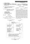
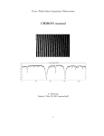
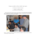
Combined MASS/DIMM instrument for
measurements of the atmospheric optical
turbulence
A Proposal to:
European Southern Observatory (ESO)
by Victor G. Kornilov,
Sternberg Astronomical Institute, Moscow University
September 21, 2005
1
1
Project goals
The first Multi-Aperture Scintillation Sensor (MASS) was developed in a collaboration of Sternberg
Institute (Moscow University) with Cerro-Tololo Inter-American Observatory and European Southern Observatory in 2001 – 2002 [1, 2] . The commissioning, test measurements and multiple crosscomparisons with different methods of the atmospheric turbulence sensing were conducted in 2002 –
2003. They revealed the reliability of the output data (turbulence profiles, integral quantities etc) and
the capacity of this method to restore low-resolution turbulence profiles.
In general, the results obtained on seeing from two instruments, MASS and DIMM, mimic each
other [2]. Meanwhile, they start differing when the ground-layer turbulence becomes significant.
Compared to DIMM, MASS provides a wider scope of information on turbulence, but is blind to
altitudes below 0.5 km. Hence, DIMM results are complementary to MASS and allow thus to restore
the full picture of the state of atmosphere for a given moment. The good idea was to combine both
instruments as one MASS/DIMM instrument. Such device was developed and built for CTIO and
TMT site testing programs in 2004. The numerous comparisons with other methods and between
different copies show that this instrument provides and correct data on optical turbulence in the
whole altitude range.
We propose now to modify and implement new version of the turbulence profiler and seeing monitor
MASS/DIMM, optimized for ESO demands. The instrument optics will be adopted for use with standard amateur telescopes Celestron 11. Whenever a computerized mount is available, the instrument
will work unassisted. These MASS/DIMMs will be used in the following way:
• Provide identical instrumentation for the site testing program directed to establishing of an
optimal site for future ELT project. As the two year experience shows – the MASS/DIMM
copies produce the well coincided results.
• Participation in other site-testing activities and acquisition of data that are needed for calibration
of hydrodynamic turbulence modeling, with a goal of understanding mechanisms of astronomical
seeing.
2
Instrument overview
The whole MASS/DIMM instrument includes:
• Feeding Cassegrain type telescope with computerized mount.
• The MASS/DIMM device itself with MASS electronics and mechanical interface for DIMM CCD
camera.
• DIMM CCD camera with its own interface to PC computer and its own software.
• PC computer with a software for system control, data acquisition and processing.
The system components work under the computer control and can make measurements in automatic
mode without human intervention. So as the DIMM detector will be provided by another developer
we do not discuss it in details.
2
2.1
MASS/DIMM device box
The MASS/DIMM device includes following principal parts:
•
•
•
•
•
Common optics providing a light separation between MASS and DIMM channels.
MASS channel optics providing further light segmentation in to A, B, C and D sub-channels.
DIMM optical channel providing an double image on DIMM detector.
Appropriate interface for adopted DIMM CCD camera.
MASS electronics and its interface for connection to PC computer.
The MASS/DIMM device is attached to the Celestron 11 or other Cassegrain-type telescope with
similar parameters which collects the light of a single bright star to three clear sub-apertures of the
diameter about 80 – 90 mm. The view of the device is presented in Fig. 1. Light from a telescope
passes through the Fabry lens 1 which images the telescope entrance pupil in the exit pupil plane. A
special segmentator 2 is placed there. The view of the exit pupil plane is presented in Fig. 2.
The segmentator unit is more complex than the MASS PSU. It contains three parts (Fig. 2). Two
equal concave mirrors with the diameter 10 mm and curvature radius about 90 mm, covered by mask
with holes about 5.5 mm, provide two DIMM sub-apertures with the equivalent diameter 90 mm and
separation 180 mm. Light in the DIMM channel is refocused on the CCD detector 3 (of ST2000X
type, pixel size 7.4 micron) with the plate scale about 100”/mm. They form two star images, the
separation between them is a few tens arc seconds and is adjustable by sub-aperture mirrors.
The third part is similar to the MASS PSU [4], but is additionally inclined to provide the needed
(non-symmetrical) light beams direction. The outer segment diameter is 5.50 mm. The concentric
segments of the MASS segmentator have a certain curvature to provide non-divergent beams. We
plan to use plastic MASS segmentator replices for us by A.Tokovinin from original metallic PSU. The
light in the MASS channel is directed to the 4 PMTs 5 with help of four re-imaging mirrors. These
mirrors 4 form the images of the corresponding concentric pupil segments on the photo-cathodes of
the PMTs. Both MASS detectors and DIMM CCD detector work in unfiltered (white) light.
Access to the PSU is provided from the bottom side of the instrument box via a special removable
cover.
The field of view of the instrument is limited by the field aperture 6 placed in the focal plane.
The aperture has a diameter about 2 mm (2.5 arc minutes) and is needed to limit the sky background
light. Before the field aperture a removable mirror 7 is placed. This mirror is inserted into the beam
and reflects the light into viewer 8 for the star initial pointing. The field of view of the viewer is as
wide as 10 arc minutes.
2.2
Electronics
Instrument electronics is similar to the MASS electronics in its principles (See [4, 8]). But all logical
modules will be physically located only on two printed circuit boards 9 to minimize connector problems.
All four PMTs and appropriate amplifier-counter modules are assembled in a single detector module
11 on a single PCB. A protective shutter is provided for this module.
The rest of electronics — the power DC/DC converter +12/+5 V, the high voltage converter and
so on, which dissipate some heat, — is located on the second PCB mounted in the electronic box 12.
These two boards are connected by special connectors.
3
1
7
4
8
6
3
4
9
5
8
2
Figure 1: Draft view of the instrument box (see text)
Figure 2: Light separation between MASS and DIMM channel into exit pupil plane. Exit pupil is
shown by blue. Yellow — MASS segmentator unit (PSU). DIMM masks are shown by cyan. Black —
the placement of DIMM re-imaging mirrors DM1 and DM2
External connections for instrumental box are +12 V DC power supply and RS485 line to a
standard PC computer. The line connects to the LPT port on PC via a custom-made RS485/LPT
data converter. We plan to increase twice the transmission rate to provide sorter microexposure (0.5
ms).
Working temperature range of all electronics is -10..+50 C. Heat dissipation is about 4 W.
3
Software
So as a DIMM control software and telescope software remain out of the scope of this work, we can
not propose the optimal solution of the separate program interactions. But the method which was
used in matching of the MASS-LITE and ASM at Paranale, can be used for this project too.
In this scheme, additional program (supervisor) controls the MASS observational process by sending messages (commands) to the MASS control program Turbina, checking before the status of the
DIMM/ telescope program.
All the programs share the single star list and some other service data needed for their work. For
the synchronous DIMM and MASS work, the observation manager role is retained for DIMM which
will decide on selection of the next star, shutting down and so on.
3.1
RS485 line driver: porting to Linux kernel 2.6
The data exchange between the host computer and the device is maintained via the half-duplex
interface line based on a physical standard RS-485. The adaption of the line to the computer is made
using the special converter RS485/LPT. The driver which serves this converter is developed for the
Linux kernel versions 2.4.
5
The new Linux distributions are supplied with a kernel of a new version 2.6. Even if users of
MASS/DIMM devices would like to change the Linux version to a newer one, the use of the current
RS485 driver under the new kernel is not possible. These limitations on a use of existing driver complicate software installation and maintenance. We propose, as an outcome of the previous discussion,
to start the MASS software upgrade with an RS485 driver modification making it compatible with
new Linux kernel 2.6.
3.2
The development of the new generation of the MASS software
The current version of Turbina program was developed primarily oriented to provide a convenient
graphic user interface (GUI). This resulted in a close inter-relation of the flux measuring and device
manipulation modules with the GUI. When the question on an automatic mode arose, some additional
capabilities for the Turbina exchange with other components of the complex programs system were
simply added with no serious reconsideration of Turbina basics.
These later inserts have caused a considerable interference with the general concept of Turbina and,
although most of these consequences were localized and corrected in 2003–2004, the full confidence
in reliability and adequate view of the existing software are still absent. Multiple discussions of this
problem with our colleagues which are interested in the MASS usage appeared also quite helpful and
eventually lead to a principally different concept of the Turbina general structure.
The new concept is based on a clear division of functionality and resources between different
Turbina modules and the detailed development of the interface and protocols of their exchange. The
main idea of this concept is to provide the most reliable performance of the measurement core, which
consumes the minimal resources and makes only the limited amount of job. All remaining work (data
processing, user interfaces etc) will be separated in other programs detached from the Turbina core.
Up to now, we plan to divide the Turbina program into three independent program modules (see
Figure). The first one works with the device and makes the statistical treatment of the PMT fluxes
providing the raw measurements results. This is a core and it is organized like a server which may
be accessed by other modules via sockets to manage the measurements. The sole output of the core
will be the file with the statistical moments of fluxes and the device parameters. This will be the
only module which is mandatory to observe with MASS and which must be run on the device host
machine.
The second module is the data interpreter. It consumes the core output, computes the scintillation
indices, turbulence characteristics, etc., and stores the results in the output mass-file. It may be started
at any moment on any machine and thus may do the on-line or stand-alone data processing. All the
information which is needed for its work is obtained from the statistics and parameters read from
the input file. In case of on-line processing, the data interpretation occurs immediately after the new
information is found in the input.
Finally, the graphic user interface will be provided which in some respect resembles the current
Turbuna windows. It will help to make the core management simple and vivid, as in the current
version. Most often this is needed while making the test measurements or determining the device
parameters. Another function of the GUI is the on-line visualization of the measurement results
which are currently under way at a given site. In case of robotic site testing, the GUI will be mostly in
use via remote connection for data inspection (observations management is normally done by a local
automatic supervisor, via the same socket connection).
6
MASS device
RS485
Turbina core
socket: commands
stm + params file
*.stm
Data interpreter
output data file
*.mass
Graphical interface socket: data samples
Figure 3: Proposed re-structurization of the Turbina program in several program modules. Dotted
line denotes the possible location of modules on different machines.
3.3
The support and maintenance of the software during campaigns
As before, we are going to continue the checks of the performance of the software while the MASS
measurements are under way at several sites. This includes bug fixing in Turbina modules, testing of
the new software components in real observation conditions, support of organization of inter-program
communication for management of robotic observations, support for migration from Linux kernel 2.4
to kernel 2.6 (Turbina recompilation and new RS485 driver installation).
4
Work scope and Implementation plan of Moscow team
We propose to carry out the following parts of the whole MASS/DIMM project: A preliminary work
plan which is given below, assumes that the contract will be effective in the nearest future:
1. Development and design of opto–mechanics and electronics (October 2005)
•
•
•
•
Adaptation of optics to Celestron 11 telescope.
Redesign of opto–mechanical instrument box.
Modification of electronics
Preparation of the detailed drawings and specifications.
2. Fabrication of optics and electronics (October 2005)
• Manufacturing of non-standard optics.
• Fabrication of the electronics.
3. Software development and debugging (November 2005 — February 2006)
7
• RS485 driver for 2.6 kernel development.
• TURBINA new version development.
• Supervisor adaptation.
4. Instrument assembly, alignment, testing and commissioning (December 2005)
•
•
•
•
•
5
5.1
Assembly of the instrument.
Optics alignment (CCD camera including) and testing.
Software installation and testing.
Preparation of the documentation.
Participation in the commissioning.
Cost estimate
Development costs
Development costs do not depend on the number of delivered instruments. Partially, the costs for
new software are covered by TMT program via AURA contract. Below the part of ESO expenses are
shown.
Cost, Euro
Subject
Hardware
Recalculation of optical scheme for C11 telescope
Redesign of the device, drawings and specifications
Electronics modification
Documentation
1,000
3,000
1,300
700
Software
RS485 driver for 2.6 kernel development
Turbina program implementation
Supervisor modification
Software support and maintenance during campaigns
Documentation
Overhead
2,000
5,000
1,000
3,000
800
4,150
21,950
Total
5.2
Device cost
Cost per one delivered instrument is given below. The costs for an standard optical elements, some
electronics components (PMT mainly) which either cannot be purchased or is more expensive in
Moscow, and cost of mechanical parts manufacturing, are not included. Full list of the purchased
items is appended to the proposal.
8
It is decided that assembly and testing of the complete devices will be done at ESO Garching, the
expenses for logging and so on, are not included here and will be provided by ESO.
Subject
Cost, Euro
Fabrication of non-standard optics
Fabrication of electronics
Assembly of the device
Alignment and testing
Further maintenance
Overhead
800
1,000
600
600
300
700
Total
4,000
We propose a contract with V. Kornilov for four MASS/DIMM devices for a total amount of 37,950
EURO.
References
[1] Kornilov V., Tokovinin A., Voziakova O., Zaitsev A., Shatsky N., Potanin S., Sarazin M. MASS:
a monitor of the vertical turbulence distribution Proc. SPIE, 2003, V. 4839, P. 837-845 (Waikoloa
SPIE Conference, 2002).
[2] Tokovinin A., Kornilov V., Shatsky N., Voziakova O. Restoration turbulence profile from scintillation indices Mon. Not. R. Astron. Soc. V.343, p.891, (2003).
[3] Tokovinin A., Baumont S., Vasquez J. Statistics of turbulence profile at Cerro Tololo. MNRAS,
2002, submitted.
[4] Kornilov V., Potanin S., Shatsky N., Voziakova O., Zaitsev A. Multi-Aperture Scintillation Sensor.
Final design document February 28, 2002.
[5] Kornilov V., Potanin S., Shatsky N., Voziakova O., Zaitsev A. Multi-Aperture Scintillation Sensor.
Operation and User Manual. February 28, 2002.
[6] Kornilov V., Potanin S., Shatsky N., Voziakova O., Zaitsev A. Multi-Aperture Scintillation Sensor.
Software Reference Manual. February 28, 2002
[7] Kornilov V., Potanin S., Shatsky N., Voziakova O., Zaitsev A. Multi-Aperture Scintillation Sensor.
Engineer Guide. February 28, 2002
[8] Kornilov V., Potanin S., Shatsky N., Voziakova O., Zaitsev A. Multi-Aperture Scintillation Sensor.
Detailed Design. February 28, 2002
9
Table 1: The specifications for MASS/DIMM purchased optical elements.
Des.
Part and parameters
Manufacturer
Stock name/number
Total q-ty
Rem.
1
Fabry lens 1
Focal length: -150 mm
Diameter: 25.0+0.0
−0.2 mm
Edmund Optics
ACH25x-150MgF2 TS
NT45-423
4
1
2
Fabry lens 2
Focal length: 75 mm
Diameter: 25.0+0.0
−0.2 mm
Edmund Optics
ACH25x75MgF2 TS
NT32-325
4
1
3
Viewer lenses
Focal length: 50 mm
Diameter: 18 mm
Edmund Optics
ACH18x50MgF2 TS
NT32-913
8
1
4
Kellner eyepiece
Focal length: 12 mm
Barrel diameter: 1 14 inches
Any
—
4
1. See specification at www.edmundoptic.com
Table 2: The specifications for MASS/DIMM purchased electronical elements.
Des.
Part and parameters
Manufacturer
Stock name/number
1
Photomultiplier R7400P
Hamamatsu
R7400P
2
Sockets for PMT
Hamamatsu
E678-12M
3
HV converter +12/1KV
WME
TC-1N-12LS
4
RS485 cable: 2 twisted
pairs, shielded, 120 ohm
Belden
#8132
5
Connectors
(for cable, soldering)
Any
DB-9F with shell
DB-9M with shell
6
Universal adaptor AC/DC
∼120-240V/+12V, 1.5A
ripple less 100mV
Any
Total q-ty
Rem.
16 + 2 spar
1
20
1
4 + 1 spar
2
100 m
3
5
5
5
1. See specification at www.hamamatsu.de
2. See specification at www.wme.com
3. See specification at www.belden.com
10