1
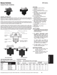
NOT to be distributed outside of FM Approvals and its affiliates except by CUSTOMER
APPROVAL REPORT
ST420-LT AND ST420-DI SHAFT TACHOMETER
SENSORS FOR USE IN HAZARDOUS LOCATIONS
Prepared for:
Electro-Sensors Inc.
6111 Blue Circle Dr.
Minnetonka, MN 55343 USA
Project ID: 3043444
Class: 3616 - FMCU
Date of Approval: 26 January 2012
Authorized by:
J. E. Marquedant – Group Manager, Electrical
FM Approvals
1151 Boston-Providence Turnpike
PO Box 9102
Norwood, MA 02062
Page 1 of 11
FM APPROVALS
Project ID: 3043444
I
INTRODUCTION
1.1
Electro-Sensors Inc. (manufacturer) requested FM Approval of their ST420-LT and ST420-DI
Tachometer Sensors listed in Section 1.5 to be in compliance with the applicable requirements of the
standards listed in Section 1.3 and 1.4.
1.1.1
For FM Approval for use in the United States as Dust-ignitionproof for Class II/III, Division 1 and 2,
Groups E, F and G hazardous (classified) locations, indoors and outdoors (Type 4X/IP65).
1.1.2
For FM Approval for use in Canada as suitable for use in Class II, Division 1 and 2, Groups E, F and
G, and Class III, Division 1 hazardous locations, indoors and outdoors (Type 4X/IP65).
1.2
This report may be freely reproduced only in its entirety and without modification.
1.3
The equipment described in this report was shown to comply with the applicable requirements of
the following standards for use in the United States.
Title
Class Number
Issue Date
Electrical Equipment for use in Hazardous (Classified)
Locations General Requirements
FM Class 3600
1998
Electrical Equipment for Measurement, Control and
Laboratory Use
FM Class 3810
2005
ANSI/IEC60529
2004
Enclosures for Electrical Equipment (1000 Volts Maximum) ANSI/NEMA 250
2003
Degrees of Protection Provided by Enclosure (IP Code)
1.4
The equipment described in this report was shown to comply with the applicable requirements of
the following standards for use in Canada.
Title
Class Number
Bonding of Electrical Equipment
CSA C22.2 No.
0.4
Threaded Conduit Entries
CSA C22.2 No.
0.5
Enclosures for use in Class II Groups E, F and G Hazardous CSA C22.2 No. 25
Locations
Special Purpose Enclosures, Industrial Products, A National CSA C22.2 No. 94
Standard of Canada
1.5
Issue Date
2004
1982
(R2003)
1966
(R2004)
1991
Industrial Products, Forming Part of Canadian Electrical
Code, Part II Safety Standards for Electrical Equipment
CSA
C22.2 No. 142
1987
(R2004)
Degrees of protection provided by enclosures (IP Code)
CSA C22.2 No.
60529
2005
Listing - The equipment described in this report will appear in the Approval Guide, an online
resource of FM Approvals, as follows:
Page 2 of 11
FM APPROVALS
Project ID: 3043444
1.5.1
United States Listing:
ST420-LT-a. Tachometer Sensor
DIP/II,III/1,2/EFG/T5 Ta=80°C; Type 4X, IP65
a = Frequency Range: L, H or C-XXXX (C-XXXX is customer requested frequency range with 4
digit tracking no.).
ST420-DI-a. Tachometer Sensor
DIP/II,III/1,2/EFG/T5 Ta=80°C; Type 4X, IP65
a = Frequency Range: L, H or C-XXXX (C-XXXX is customer requested frequency range with 4
digit tracking no.).
1.5.2
Canada Listing:
ST420-LT-a. Tachometer Sensor
DIP/II,III/1,2/EFG/T5 Ta=80°C; Type 4X, IP65
a = Frequency Range: L, H or C-XXXX (C-XXXX is customer requested frequency range with 4
digit tracking no.).
ST420-DI-a. Tachometer Sensor
DIP/II,III/1,2/EFG/T5 Ta=80°C; Type 4X, IP65
a = Frequency Range: L, H or C-XXXX (C-XXXX is customer requested frequency range with 4
digit tracking no.).
1.6
As described in this report, the construction of the ST420-LT and ST420-DI Tachometer Sensors
provide for the degree of protection against electrical shock, fire and injury required for hazardous
locations.
II
DESCRIPTION
2.1
The ST420-LT and ST420-DI sensors are tachometer sensors used for measuring the speed of a shaft.
The sensors detect magnetic pulses from a rotating shaft which has magnetic pulser targets mounted
on the shaft (disc type or wrap type). The output from the transmitters is a continuous 4 – 20 mA
analog signal in direct proportion to the pulse frequency (rotating shaft speed). The ST420-LT and
ST420-DI sensors are available in three different frequency range options, low (option L for 0.2667 to
26.67 Hz), high (option H for 0.2667 to 266.7 Hz) or customer (option C) supplied. The ST420-LT
and ST420-DI sensors are packaged within a M18x1 stainless steel sensor housing with either a ½
inch NPT female conduit thread type (ST420-DI version) for ½ inch trade size conduit connection or
with a flexible liquid tight fitting for connection with ½ inch liquid tight flexible conduit (ST420-LT
version).
2.2
The ST420-LT and ST420-DI sensors are rated for 8 to 30 Vdc and shall be powered by a Class II
power supply. The ST420-LT and ST420-DI sensors come complete with a NRTL listed, 10 foot
length of shielded, 2 x 24 AWG stranded copper wire rated for 105°C for electrical connection using a
suitable Class II/III wiring method to a suitably rated junction box. The ambient temperature range of
the ST420-LT and ST420-DI sensors are rated for use from -20°C to +80°C.
Page 3 of 11
FM APPROVALS
Project ID: 3043444
III
EXAMINATIONS AND TESTS
3.1
The following test samples, considered to be representative of the ST420-LT and ST420-DI sensors
were examined, tested, and compared to the manufacturer’s drawings. All testing was conducted at
FM Approvals facilities in West Glocester, Rhode Island USA. All test data is on file at FM
Approvals under Project ID: 3043444 along with other documents and correspondence applicable to
this program.
Test sample 1 – ST420-LT Tachometer sensor, with 10 foot length of ½ inch trade size flexible liquid
tight conduit attached. The test sample also include a 10 foot length of 2x24AWG shielded stranded
flying cable wire pre-installed within the liquid tight conduit for electrical connection.
Test sample 2 – ST420-DI Tachometer sensor, with 10 foot length of 2x24AWG shielded stranded
flying cable wire. The body of the sensor incorporates a ½ inch female NPT trade size conduit
connection. Three wraps of Teflon tape was used on the conduit used prior to the environmental
protection tests.
3.2
Dust-Ignitionproof Tests - The following tests verified the suitability of the ST420-LT and ST420DI sensors as suitable for Class II and III, Division 1 and 2, Groups E, F and G for hazardous
locations for use in US and Canada.
3.2.1
Impact Tests – Test samples 1 and 2 were subjected to impacts from a 25 mm spherical steel tip at a 7
Joule magnitude. The impact was obtained by dropping a 1.0 kg weight from a height of 0.7 m onto
various test points on the test samples. Results were satisfactory in that no damage occurred to the test
samples that would invalidate the Type of Protection.
3.2.2
Dust Exclusion Test – Test Samples 1 and 2 were individually suspended in a circulating dust
atmosphere of 200 mesh talc. The test sample was connected to a vacuum pump adjusted to draw a
vacuum of 20 mBar on the sample. The test lasted a total of eight hours and at the conclusion of the
test, the test sample was removed from the test chamber; excess dust was removed from the surface
and opened. Results are satisfactory as the sensors were found to have excluded the entry of dust.
3.2.3
Dust Blanketing Temperature Test - Surface temperature tests were waived on the ST420-LT and
ST420-DI sensors, as the maximum power dissipated by the device is less than 1 watt. The power
dissipation would not produce a temperature rise greater than 20°C in the rated 80°C ambient. This
qualifies the manufacturer’s request for a temperature code of T5 at a 80°C maximum ambient
temperature rating. This is satisfactory.
3.3
Protection Against Electrical Shock, Fire and Injury – Electrical utilization equipment
acceptability is based on the ability of the equipment to minimize the risk of electrical shock, injury
and fire. The following verifies that the ST420-LT and ST420-DI sensors were found to meet these
requirements for US and Canada.
3.3.1
Protection from Electric Shock - The maximum normal operating parameters of the ST420-LT and
ST420-DI sensors for use in outdoor wet locations, are specified to be less than 16Vrms, 22.6 V peak,
35 Vdc. As for Canada, the circuit voltage does not have a voltage more than 30Vrms or 42.4V peak
and is classified as an Extra-low Voltage Class 2 circuit. Therefore, the equipment is not considered
to be ‘Hazardous Live’ for the USA and as for Canada pose a ‘Shock Hazard’.
3.3.1.1 Protective Ground - The ST420-LT and ST420-DI sensors contains an external protective ground
terminal connection. This external ground terminal connection is installed pursuant to the user’s
Page 4 of 11
FM APPROVALS
Project ID: 3043444
manual and is an integral part of the housing. Refer to Sections 4.1.4 and 4.1.5 for protective ground
connection depictions. This is satisfactory.
3.3.1.2 Dielectric Tests - A test potential of 500 Vac was applied for 1 minute between the input supply
terminals of test sample 2 tied together and the protective ground terminal (outer sensor case) with no
occurrence of breakdown. This is satisfactory.
3.3.1.3 Field Wiring - The ST420-LT and ST420-DI sensors come complete with a NRTL listed, 10 foot
length of shielded, 2 x 24 AWG stranded copper wire rated for 105°C for electrical connection using a
suitable Class II/III wiring method to a suitably rated junction box. No consideration was needed in
regards to vibration as the lead wires conductor size was not smaller than 24 AWG. This is
satisfactory.
3.3.2
Protection Against Mechanical Hazards - The ST420-LT and ST420-DI sensors do not have any
moving parts, provisions for carrying or lifting, provision for wall mounting, parts which are likely to
become expelled in the event of a fault. It is considered fixed equipment. As a result, no further
evaluation is needed for protection against mechanical hazardous. This is satisfactory.
3.3.3
Mechanical Resistance to Shock, Impact and Resistance to UV radiation - Rigidity, shock and
impact testing was waived as the ST420-LT and ST420-DI sensors is made from solid metallic
fabricated material as described in Section II of this report. There are no parts likely to crack or loosen
which will cause a hazard such as electric shock, fire, moving parts, damaging of barriers or
invalidated creepage distances. As a result, no further evaluation is needed for protection against
shock and impact. This is satisfactory.
3.3.4
Protection Against the Spread of Fire - The PCB shaft tachometer board has a 94V-0 flammability
rating, and the electronics and connection facilities of the ST420-LT and ST420-DI sensors are
enclosed in a metallic housing. This design construction and the lower power dissipation determined
satisfactory compliance against internal spread of fire. This is satisfactory.
3.3.5
Equipment Temperature Limits and Resistance to Heat - The ST420-LT and ST420-DI sensors
are considered to be industrial measurement equipment. There are no parts which need to be touched
for functionality reasons. The maximum temperature of the field wiring within the enclosure was
determined to be approximately the maximum ambient (80˚C) due to the low power of the equipment.
The equipment is suitably factory wired with conductors rated to 105˚C, 300V. This is satisfactory.
3.3.6
Protection against Hazards from Fluids - The ST420-LT and ST420-DI sensors were examined to
determine if the process of cleaning and the spillage of liquids could result in a hazard. The ST420LT and ST420-DI sensors are not supplied with hazardous live voltages and has a water tight
enclosure. As a result, external cleaning and spillage of liquids will not present a hazard. This is
satisfactory.
3.3.7
Process Pressure Test - The ST420-LT and ST420-DI sensors are not intended to be used in a
process which contains liquids. The process pressure test is not applicable. This is satisfactory.
3.3.8
Protection against Radiation, Laser Sources, and Against Sonic and Ultrasonic Pressure - The
ST420-LT and ST420-DI sensors is not a source for producing radiation, laser emissions, sonic or
ultrasonic pressure. As a result, no further evaluation is needed. This is satisfactory.
3.3.9
Protection Against Liberated Gases, Explosion and Implosion - The ST420-LT and ST420-DI
sensors do not contain gases, batteries or high vacuum devices. As a result, no further evaluation is
Page 5 of 11
FM APPROVALS
Project ID: 3043444
needed for protection against Liberated Gases, Explosion and Implosion. This is satisfactory.
3.3.10 Components - The ST420-LT and ST420-DI sensors do not have any components such as motors,
over-temperature protection devices, fuse holders accessible to the operator, transformers, etc. which
are required to be examined for electric shock, fire and injury. The PCB shaft tachometer board is
specified as FR4 laminate, Green Glass Epoxy, with a 94V-0 flammability rating or better. This is
satisfactory.
3.3.11 Protection by Interlocks - The ST420-LT and ST420-DI sensors do not contain any protection by
interlocks therefore no further examination was needed. This is satisfactory.
3.4
Environmental Tests - The following tests verified the Type 4X environmental rating for the ST420LT and ST420-DI sensors.
3.4.1
Pre-Conditioning – As the ST420-LT sensors employ resilient non-metallic gaskets / o-ring seals
which provide protection against the ingress of water and dust, the complete enclosure with such
gaskets / seals in place was subjected to the following preconditioning. Test sample 1 was subjected
to 90% relative humidity at a temperature of (20 ± 2) K above the maximum service temperature, (i.e.,
95°C) for 168 hours.
3.4.2
Hosedown Test - A pre-conditioned test sample 1, as described in Section 3.4.1, and test sample 2
were subjected to a stream of water from a hose with a 1 inch (25.4 mm) diameter nozzle, delivering
65 gallons (246 l) per minute. The water was directed at all points of potential water entry such as
seams, joints, external operating mechanisms, and such. The nozzle was moved along each test point
at a uniform nominal rate of 6 mm/sec (¼ in/sec) at the sample from all sides from a distance of 10 to
12 feet (3 to 3.7 m) for a minimum of 5 minutes. At the conclusion of the test, the enclosure sample
was opened and was found to have excluded the entry of water. This is satisfactory.
3.4.3
Corrosion Test – This testing was waived as the materials used for the construction of the ST420-LT
and ST420-DI sensors are stainless steel type. This is satisfactory.
3.4.4
External Icing Test - This test was waived, as the ST420-LT and ST420-DI sensors do not contain
areas that could accumulate ice and have no external operators that could be damaged by ice. This is
satisfactory.
3.5
Ingress Protection Rating Tests – The following tests verified the IP65 rating for the ST420-LT and
ST420-DI sensors.
3.5.1
Dust Exclusion Test (IP6X) - This testing was satisfactorily carried out as described in Section 3.2.2.
This is satisfactory.
3.5.2
Hosedown Test (IPX5) – Test samples 1 and 2 were subjected to a stream of water from a hose with a
¼ inch (6.3 mm) diameter nozzle, delivering 3.3 gallons (12.5 l) per minute. The stream of water was
applied on all joints for a period of at least 3 minutes from a distance of 8.2 to 9.8 feet (2.5 to 3 m) for
three minutes. At the conclusion of the test, the sample was opened and was found to have excluded
the entry of water. This is satisfactory.
Page 6 of 11
FM APPROVALS
Project ID: 3043444
IV
MARKING
4.1
The ST420-DI and ST420-LT Sensors’ certification markings and labels are found in the
manufacturer’s users manual and as labeled on the shipping box since the equipment was determined
to have insufficient space for certification marking and product ratings. A certification reference label
is also applied by the user after installation onto the product as indicated in the user’s manual. Below
in the following Sections are depictions of the marking methods used for the ST420-LT and ST420-DI
sensors.
4.1.1
ST420-DI and ST420-LT Sensors Shipping Box Labels –
4.1.2
ST420-DI User’s Manual 990-003901 markings –
Page 7 of 11
FM APPROVALS
Project ID: 3043444
4.1.3
ST420-LT User’s Manual 990-00902 markings –
4.1.4
ST420-LT user applied Certification Reference label as depicted in User’s Manual 990-00902 as
applied by installer after installation -
4.1.5
ST420-DI user applied Certification Reference label as depicted in User’s Manual 990-00901 as
applied by installer after installation –
Page 8 of 11
FM APPROVALS
Project ID: 3043444
V
REMARKS
5.1
Installation in the United States of America shall be in accordance with the National Electrical Code®,
ANSI/NFPA-70, and the manufacturer’s instructions.
5.2
Installation in Canada shall be in accordance with the Canadian Electrical Code C22.1, and the
manufacturer’s instructions.
5.3
The product(s) described in this report were certified by FM Approvals under a Type 3 Certification
System as identified in ISO Guide 67.
VI
FACILITIES AND PROCEDURES AUDIT
The manufacturer's design control and manufacturing facility located in Minnetonka, Minnesota is
subject to follow-up audit inspections. The facility and quality control procedures in place have be
found to be satisfactory to manufacture product identical to that examined and tested as described in
this report. These facilities are subject to follow-up audit inspections.
VII
MANUFACTURER’S RESPONSIBILITIES
7.1
The manufacturer shall advise FM Approvals of all proposed changes to the documentation listed in
Section VIII of this report through FM Approvals Form 797, Approved Product Revision Report. No
Page 9 of 11
FM APPROVALS
Project ID: 3043444
changes of any nature shall be made unless notice of the proposed change has been submitted and
written authorization obtained from FM Approvals.
7.2
On 100% of production, the manufacturer shall inspect the protective grounding system.
VIII
DOCUMENTATION
The following drawings depict the design of the products identified in Section 1.5 and are on file at
FM Approvals, blueprint file 3043444.
Drawing No.
213-000030
213-012920
213-012921
213-012922
213-012930
213-012931
213-012932
300-004601
305-006402
305-006403
535-052300
698-059400
750-001100
750-001100
BOM
800-001900
BOM
800-0019XX
800-004100
BOM
800-0041XX
990-003901
990-003902
IX
Revision
Level
A
A
A
A
A
A
A
B
B
A
D
A
D
D
Drawing Title
B
ST420-DI-L 2 - 200 RPM, 8 PPR
B
B
ST420-DI Final Assembly
ST420-LT-L 2 - 200 RPM, 8 PPR
B
B
ST420-LT Final Assembly
ST420-DI 4-20mA Shaft Tachometer Sensor/Transmitter
USERS MANUAL
ST420-LT 4-20mA Shaft Tachometer Sensor/Transmitter
USERS MANUAL
A
Label Sensor Alignment 0.375" DIA
Label ST420-DI Cable
Label ST420-DI FM Reference
Label ST420-DI FM Shipping Box
Label ST420-LT Cable
Label ST420-LT FM Reference
Label ST420-LT FM Shipping Box
Gland T&B 5332 Style 316SS
Housing Sensor Closed M18x1 SS 1/2" Flex
Housing Sensor Closed M18x1 SS 1/2" NPT
PCB, Shaft Tach 4-20
Schematic - PCB ST420
ASSY PCB ST420
ASSY PCB ST420
CONCLUSION
The equipment identified in Section 1.5 of this report meets FM Approvals requirements. Since a duly
signed Master Agreement is on file for this manufacturer, FM Approval is effective the date of this
report.
Page 10 of 11
FM APPROVALS
Project ID: 3043444
TESTING BY:
C. Burch
EXAMINATION BY: C. Burch
PROJECT DATA RECORD: 3043444
ATTACHMENTS:
None
REPORT BY:
REPORT REVIEWED BY:
________________________________
Christopher Burch
Senior Engineer
Hazardous Locations
________________________________
Andrew Lozinski
Technical Team Manager
Hazardous Locations
Page 11 of 11