1
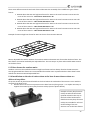
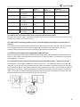
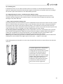
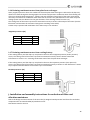
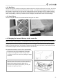
 There are 4 different manuals and each of them illustrates the assembly of the 4 different types of base frames: 1. Manual about the 150 mm high base frames for AHUs in the sizes from DV 10 to DV 40. The name of this manual is – Base frame 150 DVZ 10 ‐ 40 2. Manual about the 150 mm high base frames for AHUs in the sizes from DV 50 to DV 150. The name of the manual is – Base frame 150 DVZ 50 ‐ 150 3. Manual about the 250 mm high base frames for AHUs in the sizes from DV 10 to DV 40. The name of the manual is – Base frame 250 DVZ 10 ‐ 40 4. Manual about the 250 mm high base frames for AHUs in the sizes from DV 50 to DV 150. The name of the manual is – Base frame 250 DVZ 50 ‐ 150 Example of 150 mm high base frame for AHUs in the size from DV 50 to DV 150 Mount adjustable feet with a distance of maximum 1500 mm between each foot under the base frame. The base frame can now be levelled by the adjustable feet. The next step is to place and assemble AHU sections on the base frame. i.2.5Baseframesforoutdoorunits
Outdoor units must be installed on 250 mm high base frames and are always fitted to the AHU sections. Hot‐dip galvanized base frames are recommended for outdoor units. Systemair delivers these base frames without the above mentioned adjustable feet. i.2.6Installationonthesiteofunitsectionsatthebaseframewhensectionsare
deliveredonpallets.
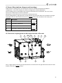
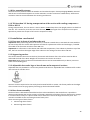
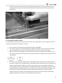
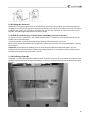
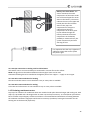
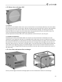
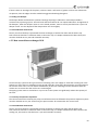
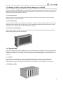
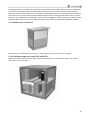
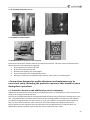
Lift up the section by hand manual forklifts to the level where the underside of the section is even with the overside of the base frame. 1. Pull the section to the correct position on the base frame by lifting straps – it is maybe necessary to support the section by heavy duty furniture trolleys (see the photos below) Example of heavy duty furniture trolley turned with the wheels upwards. Placed in this way on the forks of the hand manual forklifts the heavy duty furniture trolleys are suitable for safe and careful rolling of the unit sections over to the base frames. 27