1
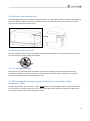
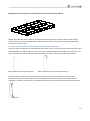
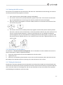
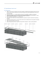
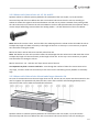
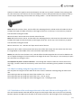
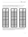
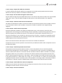
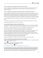
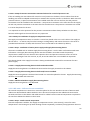
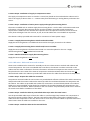
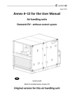
Danvent DV, Danvent TIME
Air Handling Units
GB
Transport and Installation Manual
Version 1.02
Master version
1
2
Introduction
Detailed table of content on the following pages
1. Transport
2. Installation
2.1 Installation of air handling units and ducts
2.2 Installation of steel roof
2.3 Electrical installation and plumbing
2.3.1 Electricity for motors and electrical heater batteries in
units without cabinet
2.3.2 Electricity for units delivered with control system
2.3.3 Plumbing – Pipes for water and/or refrigerant, valves and
drains
2.4 Protection measures
2.5 Dismantling and disposal
2.6 General
3
Contents
1. TRANSPORT
7
1.1 Unloading by fork-lift truck
7
1.2 Unloading by crane
7
1.3 Lifting a unit with a base frame
7
1.4 Roof unit with bitumen roof
8
1.5 Roof unit with steel roof
8
1.6 Pre-assembly storage
8
1.7 Tilt less than 30˚ during transportation of the section with cooling compressor - DVU.
8
2. INSTALLATION
9
2.1 Installation of unit and ducts
2.1.1 Adjustable feet under legs or base frame
2.1.2 Supporting surface
2.1.3 Base frame assembly
2.1.4 Protection of base frame under unit installed outdoors
2.1.5 Joining the AHU sections
2.1.6 Installing an air distributor
2.1.7 Fitting the ductwork
9
9
9
9
10
11
11
11
2.2 Installation of steel roof
2.2.1 Overview
2.2.2 Mount rails. Units of size 10, 15, 20, and 25
2.2.3 Mount rails. Units of size 30 and units larger than size 30.
2.2.4 Roof overhang along the long sides of the unit
2.2.5 Calculation of the overhang at the ends of the unit. Mount overhang profile – G1.
2.2.6 Foam bands between rails and roof plates – mount roof plates.
2.2.7 Foam bands between roof plates
2.2.8 Mount roof plates – some of them are overlapping by 2 ribs
2.2.9 Mount overhang profile – G5 on the other end of the unit.
2.2.10 Mount side profiles and corners along the edges of the roof to protect persons
2.2.11 Apply sealing on plate joints to ensure water resistance.
12
12
13
13
14
14
17
17
17
17
18
19
2.3. Electrical installation and plumbing
2.3.1 Electricity for motors and electrical heater batteries in units without cabinet
2.3.1.1 Before start-up
2.3.1.1.1 Damper motors
20
20
20
20
4
2.3.1.1.2 Rotary heat exchanger with constant speed
2.3.1.1.3 Rotary heat exchanger with variable speed
2.3.1.1.4 Electrical heater battery
2.3.1.1.5 Connection of motors for fans
2.3.1.1.6 Frequency converters
2.3.2. Electricity for units delivered with control system
2.3.2.1 TIME units – delivered in several sections
2.3.2.1.1 Step 1: Prepare the cables for connection
2.3.2.1.2 Step 2: Pull the cables through the cable entries
2.3.2.1.3 Step 3: Install the cables in the terminal blocks
2.3.2.1.4 Step 4: Install external components.
2.3.2.1.5 Step 5: Install the Systemair Control Panel.
2.3.2.1.6 Step 6: Install cables from external components
2.3.2.1.7 Step 7: Pressure transmitters
2.3.2.1.7.1 Step 7a Pressure transmitters over fans for control in m3/h.
2.3.2.1.7.2 Step 7b Pressure transmitters mounted in ducts for control of duct pressure in Pa.
2.3.2.1.8 Step 8: Installation of supply air temperature sensor
2.3.2.1.9 Step 9: Installation of mains power supply and supply disconnecting device
2.3.2.1.9.1 Supply disconnecting device is delivered and installed
2.3.2.1.9.2 Supply disconnecting device is delivered, but not installed
2.3.2.1.9.3 Delivered without supply disconnecting device
2.3.2.2 TIME unit – delivered as one assembled unit on a base frame
2.3.2.2.1 Step 1: Install external components
2.3.2.2.2 Step 2: Install cables from external components
2.3.2.2.3 Step 3: Pull the cables through the cable entry in the bottom of the supply fan section.
2.3.2.2.4 Step 4: Install the Systemair Control Panel
2.3.2.2.5 Step 5: Pressure transmitters
2.3.2.2.5.1 Step 5a Pressure transmitters over fans for control in m3/h.
2.3.2.2.5.2 Step 5b Pressure transmitters mounted in ducts for control of pressure in Pa.
2.3.2.2.6 Step 6: Installation of supply air temperature sensor
2.3.2.2.7 Step 7: Installation of mains power supply and supply disconnecting device.
2.3.2.2.7.1 Supply disconnecting device is delivered and installed.
2.3.2.2.7.2 Supply disconnecting device is delivered, but not installed.
2.3.2.2.7.3 Delivered without supply disconnecting device
2.3.2.3 DV-units – delivered as one assembled
2.3.2.3.1 Step 1: Install external components
2.3.2.3.2 Step 2: Install cables from external components
2.3.2.3.3 Step 3: Pull the cables through the cable entries to the integrated cabinet
2.3.2.3.4 Step 4: Install the Systemair Control Panel
2.3.2.3.5 Step 5: Pressure transmitters
2.3.2.3.5.1 Step 5a Pressure transmitters over fans for control in m3/h.
2.3.2.3.5.2 Step 5b Pressure transmitters mounted in ducts for control of pressure in Pa.
2.3.2.3.6 Step 6: Installation of supply air temperature sensor
2.3.2.3.7 Step 7: Installation of mains power supply and supply disconnecting device.
2.3.2.3.7.1 Supply disconnecting device is delivered and installed.
2.3.2.3.7.2 Supply disconnecting device is delivered, but not installed.
2.3.2.3.7.3 Delivered without supply disconnecting device
20
20
20
20
21
21
21
22
22
22
22
22
22
22
23
23
23
23
23
23
23
23
24
24
24
24
24
24
25
25
25
25
25
25
25
25
26
26
26
26
26
26
27
27
27
27
27
5
2.3.2.4 DV units – delivered in several sections
2.3.2.4.1 Step 1: Prepare the cables for connection
2.3.2.4.2 Step 2: Install the cables in preinstalled cable strips under the metal covers
2.3.2.4.3 Step 3: Install the cables in the terminal blocks
2.3.2.4.4 Step 4: Install the Systemair Control Panel
2.3.2.4.5 Step 5: Install external components
2.3.2.4.6 Step 6: Install cables from external components and cables from the mains supply
2.3.2.4.7 Step 7: Pressure transmitters
2.3.2.4.7.1 Step 7a Pressure transmitters over fans for control in m3/h
2.3.2.4.7.2 Step 7b Pressure transmitters mounted in ducts for control of pressure in Pa
2.3.2.4.8 Step 8: Installation of supply air temperature sensor
2.3.2.4.9 Step 9: Installation of mains power supply and supply disconnecting device
2.3.2.4.9.1 Supply disconnecting device is delivered and installed
2.3.2.4.9.2 Supply disconnecting device is delivered, but not installed
2.3.2.4.9.3 Delivered without supply disconnecting device
2.3.2.5 DVU – general
2.3.2.5.1 Cooling compressor system according to ”The Pressure Equipment Directive” from EU
2.3.2.5.2 Certifications
2.3.2.5.3 Duties of the owner
2.3.2.5.4 Special risks
2.3.2.5.5 Water trap for condensate
2.3.2.6 The section – DVU – is installed in a DV-unit with control system for the DV-unit
2.3.2.6.1 The DVU section connected to the control system for the DV-unit
2.3.2.6.2 Mains power supply to the section – DVU
2.3.2.7 The DVU section installed in an air handling unit without control system
2.3.2.7.1 The DVU section with complete cooling compressor system
2.3.2.7.2 Mains power supply to the DVU section
2.3.2.7.3 Supply disconnecting device
2.3.3 Plumbing – Pipes for water and/or refrigerant, valves and drains
2.3.3.1 Pipe connection to coils
2.3.3.2 Avoid weight and stress on coils and coil connection pipes
2.3.3.3 Valves
2.3.3.4 Draining and water trap
27
27
27
27
28
28
28
28
28
28
29
29
29
29
29
29
29
29
30
30
30
30
30
30
30
30
31
31
31
31
32
32
32
2.4 Protection measures
33
2.5 Dismantling and disposal
33
2.6 General
34
6
1. TRANSPORT
The air handling unit – AHU - is delivered as one section or in several sections, which are to be assembled
on site. The AHU is delivered on transport pallets, legs or on a base frame. Loading and unloading as well as
transport on the site is possible by fork-lift truck or by crane using suitable lifting straps.
1.1 Unloading by fork-lift truck
The forks of the truck must be sufficiently long to avoid any damage to the AHU underside.
1.2 Unloading by crane
AHU delivered on transport pallet must be lifted by straps as shown in the illustration.
AHU delivered with legs must be lifted by straps secured to the legs as shown in the illustration.
1.3 Lifting a unit with a base frame
The holes in the base frame are to be used for the placing of lifting bars. Make sure that the bars used are
strong enough to lift the loads in question and that the straps do not touch and damage the top of the unit.
Keep the straps away from the top of the unit by bars as shown in the illustration.
7
1.4 Roof unit with bitumen roof
Avoid damaging the drip nose profiles along the bitumen roof. Keep the protection profiles of Styrofoam on
the unit until the installation has been completed. If the unit is lifted by straps, the straps must be kept
away from the drip nose profiles by bars.
1.5 Roof unit with steel roof
For units with steel plate roof, the steel plates are delivered uninstalled on a separate pallet. Do not place
any parts and do not step or walk on the plates.
.
1.6 Pre-assembly storage
The AHU must be protected from the weather and impact. Packaging must be removed and the unit
covered with tarpaulin or similar materials. In order to minimize condensation, sufficient air circulation
must be ensured between the covering and the unit.
1.7 Tilt less than 30˚ during transportation of the section with cooling
compressor - DVU.
During transportation, the unit section - DVU - must always be in the upright position or tilted less than 30˚.
If it is necessary to tilt the unit more than 30˚, the suction pipe of the compressor must point upwards to
prevent the escape of oil from the compressor sump.
8
2. INSTALLATION
2.1 Installation of unit and ducts
Important! When positioning the unit, it is recommended that a distance which is the same as the unit’s
width is kept free for service and inspection in front of the unit.
2.1.1 Adjustable feet under legs or base frame
Adjustable feet are provided in a carton box placed inside the unit.
2.1.2 Supporting surface
The surface beneath the unit must be level and even. The surface must be able to withstand the load of the
AHU.
In the case of lightweight construction or especially sensitive areas, the unit should be placed on a vibration
absorbing foundation with the necessary properties.
Remember! Duct work must be sound insulated and must not be mounted directly on beams, trusses or
other critical building parts.
2.1.3 Base frame assembly
The base frame is delivered unassembled and has to be assembled on the site before it is possible to
position and assemble the various sections of the AHU. Assembly of the base frame is illustrated on 4 pages
in a manual that is always in a plastic folder and is attached to one of the large base frame parts. This
manual is available on the site among the base frame parts.
There are two types of base frames:
1. 150 mm high base frames
2. 250 mm high base frames
There are 4 different manuals and each of them illustrates the assembly of the 4 different types of base
frames:
1. Manual about the 150 mm high base frames for AHUs in the sizes from DV 10 to DV 40. The
name of this manual is – Base frame 150 DVZ 10 - 40
2. Manual about the 150 mm high base frames for AHUs in the sizes from DV 50 to DV 150. The
name of the manual is – Base frame 150 DVZ 50 - 150
3. Manual about the 250 mm high base frames for AHUs in the sizes from DV 10 to DV 40. The
name of the manual is – Base frame 250 DVZ 10 - 40
4. Manual about the 250 mm high base frames for AHUs in the sizes from DV 50 to DV 150. The
name of the manual is – Base frame 250 DVZ 50 - 150
9
Example of 150 mm high base frame for AHUs in the size from DV 50 to DV 150
Mount adjustable feet with a distance of maximum 1500 mm between each foot under the base frame.
The base frame can now be levelled by the adjustable feet. The next step is to place and assemble AHU
sections on the base frame.
2.1.4 Protection of base frame under unit installed outdoors
Units for outdoor installation are usually delivered on base frames, and the units are built without drip nose
profile between unit and base frame, but the units are available with drip nose profile as an accessory. The
drip nose profile is made of aluminum and is mounted on the base frame. See the illustration below.
Base frame without drip nose profile
Base frame with drip nose profile (accessory)
A local installer must deliver and install further protection and maybe insulation of the base frame.
Material for protection and insulation is not delivered by Systemair. See the illustration below with an
example of insulation, protection by a steel plate and the lower part of the steel plate covered by bitumen.
10
2.1.5 Joining the AHU sections
The sections must be placed on the base frame and if the unit is delivered with 100 mm legs, the sections
must be positioned directly opposite each other.
1. Ensure that the factory-fitted rubber sealing is undamaged
2. The sections are then to be positioned directly opposite each other. If the sections are built with
legs, the adjustable feet are used to get the sections parallel and at the same height.
3. Press the sections hard together so that the rubber profiles are so flat that the iron frames of the
two sections are joined.
4. The sections are then to be locked permanently together with the black plastic-coated Systemair
Disc-Locks. The Disc-Locks are delivered in a carton box placed inside the unit. Place each Disc-Lock
over the 2 factory fitted locking pins. The discs and locking pins are not reliable for pulling the
sections together. They are only sufficient for keeping the sections well together, so just turn each
disc gently with the supplied Allen key. Use a sequence where each disc is tightened with only one
click at a time.
2.1.6 Installing an air distributor
Air distributor – only for units with centrifugal fans. If an air distributor is to be installed at the end of an
AHU, the distributor is always supplied uninstalled.
1.
Screw the extension bolts into the threaded bushes at the fan outlet.
2.
Tighten the nuts.
3.
Mount the air distributor plate between 2 nuts at the end of the extension bolts and check that the
bent edges of the distributor plate are pointing in the same direction as the air flow.
2.1.7 Fitting the ductwork
Flexible duct connections between AHU and ductwork must always be installed. Be sure that flexible duct
connections are almost fully stretched. (Flexible connections are accessories and they are placed inside the
unit). At the fan outlet on a centrifugal fan, the duct size should be as close to the outlet size as possible.
Avoid blockage and turbulence at the fan outlet.
11
2.2 Installation of steel roof
2.2.1 Overview
•
•
•
•
•
•
•
•
Mount rails A1, B2, C3, D4, E5 on the unit for support of trapezoidal roof plates (mount also rails Y
and Z on units of the size 30 and on units that are larger than size 30 longitudinally at the centreline of the units).
Place foam bands – P – on the horizontal rails A1, B2, C3 and D4 for support of roof plates.
Calculate overhang of the roof at both ends of the unit and mount roof overhang profile – G1 on
the first trapezoidal roof plate – F1 before the roof plate is mounted.
Place and mount roof plates F1, F2, F3 and so on.
Remember foam bands on the side laps between roof plates to prevent rainwater from passing
through.
Place roof overhang profile – G5 at the other end of the unit before the last roof plate is mounted.
Mount sides and corners on the roof.
Apply sealing where plates are joined to ensure water resistance - even in stormy weather.
12
2.2.2 Mount rails. Units of size 10, 15, 20, and 25
Squeeze sealant in sufficient quantity between the underside of the rails A1, B2, C3, D4, E5 and the
horizontal top side of the unit before the rails are mounted. This means that the rails are standing on
sealant to achieve the tightest connection between rails and unit to prevent rainwater from passing under
the rails and into the unit. Mount the rails A1 and B2 on the front side (the side with the inspection doors) –
use the simple self drilling screws without the sealing washer – see the illustration of the screw below.
Note: Rail B2 fits into the rail A1, and this offers the advantage that the rail B2 can be slid inside the rail A1
to adjust the length of rail B2 accurately to the length of the unit. In this way it is not necessary to spend
time and effort cutting the rail B2.
Mount the lower rails C3 and D4 on the back side of the unit.
Note: Rail D4 fits into the rail C3, and this offers the advantage that the rail D4 can be slid inside the rail C3
to adjust the length of rail D4 accurately to the length of the unit. In this way it is not necessary to spend
time and effort on cutting the rail D4.
Mount vertical rail – E5 - with the roof slope at each end of the unit
It is important to place a screw in each hole – even though the number of holes for screws seems to be
very large, a screw in each hole is necessary as the stress on the roof during stormy weather is extremely
high.
2.2.3 Mount rails. Units of size 30 and units larger than size 30.
On units of size 30 and on units that are larger than size 30, rails A1, B2, C3, D4, E5 must be mounted on the
unit for support of trapezoidal roof plates, but also rails Y and Z must be mounted longitudinally at the
centre-line of the units to hold the trapezoidal roof plates.
Squeeze sealant in sufficient quantity between the underside of the rails A1, B2, C3, D4, E5 and the
horizontal top side of the unit before the rails are mounted. This means that the rails are standing on
13
sealant to achieve the tightest connection between rails and unit to prevent rainwater from passing under
the rails and into the unit. Mount the rails A1 and B2 on the front side (the side with the inspection doors) –
use the simple self drilling screws without the sealing washer – see the illustration of the screw below.
Note: Rail B2 fits into the rail A1, and this offers the advantage that the rail B2 can be slid inside the rail A1
to adjust the length of rail B2 accurately to the length of the unit. In this way it is not necessary to spend
time and effort cutting the rail B2.
Mount the lower rails C3 and D4 on the back side of the unit.
Note: Rail D4 fits into the rail C3, and this offers the advantage that the rail D4 can be slid inside the rail C3
to adjust the length of rail D4 accurately to the length of the unit. In this way it is not necessary to spend
time and effort cutting the rail D4.
Mount vertical rail – E5 - with the roof slope at each end of the unit.
Mount the rails Y and Z on the unit with the centre-line of the rails exactly over the centre-line of the unit.
It is longitudinal on the middle of the units to hold the trapezoidal roof plates.
Notice, that rail Z fits over the lower rail Y, and this offers the advantage that the rail Z can be slided on the
rail Y to adjust the length of rail Z accurately to the length of the unit. In this way it is not necessary to spent
time and effort on cutting the rail Z.
It is important to place a screw in each hole – even though the number of holes for screws seems to be
very large, a screw in each hole is necessary as the stress on the roof during stormy weather is extremely
high.
2.2.4 Roof overhang along the long sides of the unit
The roof plates are longer than the width of the unit to ensure sufficient overhang along the sides of the
unit.
The overhang is 100 mm along each side of the smallest unit – size 10.
The overhang is 150 mm along each side of the units – size 15, 20, 25.
The overhang is 175 mm along each side of the biggest units – including size 30.
2.2.5 Calculation of the overhang at the ends of the unit. Mount overhang profile – G1.
The roof must be between 200 and 400 mm longer than the length of the unit to secure a roof overhang
between 100 mm and 200 mm at the each of the 2 ends of the unit, and the length of this overhang must
14
be calculated before the first roof plate is mounted.
The unit is delivered with 2 similar overhang profiles - G1 and G5 - one for each end of the roof. Mount one
of the 2 roof overhang profiles – G on a trapezoidal roof plate. Use the self drilling, painted screws with
sealing washers - W - see the illustration.
Note: Foam bands - P – are necessary between the overhang profile G1 and the roof plate F1. See the
illustration.
Self drilling, painted screws supplied with sealing washer for the mounting of the trapezoidal plate to the
roof overhang profile.
The total cover width of the trapezoidal roof plates always changes with the pitch of 207 mm between the
trapezoidal ribs, making up a total length of the complete roof of - for example 2070 mm, 2277 mm, 2484
mm and so on. We call this length of the total roof for RL and we call the total length of the complete unit
for AL. The trapezoidal roof must always be longer than the unit, to obtain a reasonable overhang called –
XX - of the roof at both ends.
15
In the table below you will find 40 different lengths of roofs (always changing with the 207 mm) and the
lengths of units that are ideal for each of the 40 alternative roof lengths.
Measure the total length – AL of the unit – for example 5 metres between the 4982 and 5182 mm
mentioned in the table below.
AHU length
AL
Roof
length
RL
AHU length
AL
Roof
length
RL
AHU length
AL
Roof
length
RL
1670 – 1870
2070
4568 – 4768
4968
7466 – 7666
7866
1877 – 2077
2277
4775 – 4975
5175
7673 – 7873
8073
2084 – 2284
2484
4982 – 5182
5382
7880 – 8080
8280
2291 – 2491
2691
5189 – 5389
5589
8087 – 8287
8487
2498 – 2698
2898
5396 – 5596
5796
8294 – 8494
8694
2705 – 2905
3105
5603 – 5803
6003
8501 – 8701
8901
2912 – 3112
3312
5810 – 6010
6210
8708 – 8908
9108
3119 – 3319
3519
6017 – 6217
6417
8915 – 9115
9315
3326 – 3526
3726
6224 – 6424
6624
9122 – 9322
9522
3533 – 3733
3933
6431 – 6631
6831
9329 – 9529
9729
3740 – 3940
4140
6638 – 6838
7038
9536 – 9736
9936
3947 – 4147
4347
6845 – 7045
7245
9743 – 9943
10143
4154 – 4354
4554
7052 – 7252
7452
4361 - 4561
4761
7259 - 7459
7659
The mentioned length of roof – RL - for this length of unit is 5382 mm (the delivered trapezoidal plates can
be combined to this length - RL = 5382 mm). 5382 mm minus 5000 mm is 382 mm overhang for both ends,
and 382/2 mm = 191 mm is the overhang for each end. Place the trapezoidal roof plate F1 with the roof
overhang profile G1 on rail E with an overhang of 191 mm.
16
2.2.6 Foam bands between rails and roof plates – mount roof plates.
Place foam bands P between profiles A1, B2, C3, D4 and roof plates.
The trapezoidal roof plates are mounted with the self drilling, painted screws supplied with sealing washer.
2.2.7 Foam bands between roof plates
Mount the self adhesive foam band – O - on the underlapping rib for water resistant and effective sealing
due to the small slope of the roof.
2.2.8 Mount roof plates – some of them are overlapping by 2 ribs
The width of each plate is always 1.035 mm and some of the plates have to overlap by 2 ribs to achieve the
optimal total length of the whole roof — see the illustration above.
2.2.9 Mount overhang profile – G5 on the other end of the unit.
When the last trapezoidal plate (in this example F5) has been placed on the unit, the second roof overhang
profile G5 must be pushed under the trapezoidal roof plate and mounted with the self drilling, painted
17
screw with sealing washer. Mounting must be similar to the mounting of roof overhang profile under the
trapezoidal roof plate at the other end of the unit.
2.2.10 Mount side profiles and corners along the edges of the roof to protect persons
Profiles N and O with the rectangular holes are for the long and lower side of the roof because rain can
escape through the holes. Mount the profiles type N first and the profile O last because the profile O goes
over the profile N. Mounted in this order, the profile O can match the end of the roof and the surplus
length of the profile O will just cover part of the previous profile N. Mount the profiles L and M along the
long and higher front side of the roof. Mount the 4 protection corners.
18
2.2.11 Apply sealing on plate joints to ensure water resistance.
Finish installation of the steel roof by sealing all plate joints with silicone to prevent rainwater from passing
into the unit. See examples below of joints to be sealed.
19
2.3. Electrical installation and plumbing
Pipes and cables must not obstruct the inspection doors and components which can be extracted from the
unit.
In special circumstances, when it is impossible to open the doors fully, the doors can be taken off by
removing the hinge pins.
2.3.1 Electricity for motors and electrical heater batteries in units without cabinet
2.3.1.1 Before start-up
Check carefully that the AHU is in fully accordance with all requirements in the User Manual.
2.3.1.1.1 Damper motors
The size of the damper motors must comply with the torque required by the dampers. In order to reduce
the required torque, the start of the fan should be delayed until the dampers are fully opened.
2.3.1.1.2 Rotary heat exchanger with constant speed
Electrical connection to the 3-phased gear motor must be in accordance with local statutory requirements.
Connect the motor in accordance with the motor data printed on the motor by the manufacturer.
2.3.1.1.3 Rotary heat exchanger with variable speed
Connection to the controller according to the wiring diagram printed on the cover of the control box.
Note: Inside the control box there is a test button - “Test on/off”.
2.3.1.1.4 Electrical heater battery
Connection to the electrical heater battery according to the wiring diagram that is placed behind the
inspection door of the battery.
Note: To ensure sufficient cooling of the heating elements, the fan must have an appropriate after-run
when power to the electrical heating has been cut off.
2.3.1.1.5 Connection of motors for fans
DV 10, DV 15, DV 20, DV 25 and DV 30 units have removable fans/motors for easy installation and service.
The electrical cable must therefore be sufficiently long to enable the motors to be pulled out of the unit for
service. When the fan is running, the extra cable must be wound up and fixed to keep clear of rotating
parts.
One-speed motors are to be connected as illustrated below with low speed to the left or high speed to the
right.
Two-speed motors with separate windings are to be connected as illustrated below with low speed to the
20
left, high speed to the right.
Two-speed motors with Dahlander windings are to be connected as illustrated below with low speed to the
left, high speed to the right.
2.3.1.1.6 Frequency converters
Wiring must comply with local statutory requirements and according to local restrictions based on the EMC
Directive.
2.3.2. Electricity for units delivered with control system
The control system is configured according to the specifications in the order. Report of the final test is
delivered with the unit.
2.3.2.1 TIME units – delivered in several sections
All external components are stored in a carton box placed in or with the unit. Please notice that some of
the external components are provided with cables and some of them are without cables by delivery. Some
TIME units are delivered in 2 - 8 sections for assembly on the site. TIME units are delivered with 2 cabinets.
One cabinet in the supply fan section and one cabinet in exhaust fan section. Components in the supply fan
section are connected to the cabinet in the supply fan section. Components in the exhaust fan section are
connected to the cabinet in the exhaust fan section. Cables from other sections with counter flow heat
exchanger, cooling compressor (DVU), heating and cooling coils must be connected to the marked
terminals and automatic fuses in the cabinet placed in the supply fan section. The two cabinets must be
connected to each other by the cable W600 for supply and by the cable W601 for control. The cable for
supply and the cable for control are always mounted at the factory in the cabinet placed in the exhaust fan
section. On the site the two cables must be mounted in the preinstalled cable strips to the cabinet in the
supply fan section.
No external components are connected to the cabinet by delivery of the air handling unit.
21
2.3.2.1.1 Step 1: Prepare the cables for connection
In sections without the cabinet cables from components are wound up and placed inside the sections.
Release the wound-up cables for installation inside the sections.
2.3.2.1.2 Step 2: Pull the cables through the cable entries
Pull the cables through the preinstalled cable entries in the sections and place the cables in the preinstalled
cable strips. At last - pull the cables through the cable entries in the cabinet placed in the supply fan
section.
2.3.2.1.3 Step 3: Install the cables in the terminal blocks
All cables are marked with numbers. Connect the cables to the terminals with the same numbers as well as
in circuit breakers with the same numbers. Connection of cables is explained in the supplied wiring
diagrams.
2.3.2.1.4 Step 4: Install external components.
External components could be: The supply air temperature sensor, valve motor(s), sensor for water
temperature in the heating coil (if water heating coil was requested), circulation pump (Systemair does not
deliver the pump, but terminals are present in the cabinet for a pump with a one phase motor), 2 air
pressure transmitters if it is a solution for constant pressure in the ducts, a repeater (if requested). Not all
components are delivered with every TIME unit. See the order confirmation with exact information about
and description of the accessories for this unit.
See the User Manual with the description of all accessories available for TIME units.
Temperature sensors and the Systemair Control Panel are provided with cables. Other components are not
provided with cables.
2.3.2.1.5 Step 5: Install the Systemair Control Panel.
The Systemair Control Panel with cable is stored in a carton box placed in the unit and the Systemair
Control Panel is designed for vertical installation – for example on the wall. The panel is provided with 10
metres of cable and a socket for connection with the controller inside the cabinet. The cable is not pulled
through the cable entry in the cabinet, so demount the cable at the back of the Systemair Control Panel pull the cable through the cable entry in the cabinet - adjust the length of the cable and remount the cable
in the panel (Terminal 7a = yellow cable, 7b = orange, 7c = red, 7d = brown, 7e = black). The control panel is
supplied with power from the controller, and it is not possible to use a longer cable. If 10 metres of cable is
not sufficient, a repeater must be installed between the Systemair Control Panel and the controller.
2.3.2.1.6 Step 6: Install cables from external components
Cables must not obstruct the inspection doors and prevent extraction of fans as well as rotary heat
exchangers from the sizes 10, 15, 20, 25 and 30.
2.3.2.1.7 Step 7: Pressure transmitters
22
2.3.2.1.7.1 Step 7a Pressure transmitters over fans for control in m3/h.
If the air handling unit was ordered for control in m3/h through the supply fan and the exhaust fan, the
pressure transmitters are installed inside the unit by the factory. The system has been tested, - no
installation required.
2.3.2.1.7.2 Step 7b Pressure transmitters mounted in ducts for control of duct pressure in Pa.
If the air handling unit was ordered for control in Pa of pressure in the ducts, the air volume from the air
handling unit must be adapted continuously to maintain the set point pressure in the ducts. With control of
pressure in ducts, no pressure transmitters are installed inside the unit over the fans, but the pressure
transmitters must be installed in the main ducts – one pressure transmitter in the main duct for the supply
air and one pressure transmitter in the main duct for the exhaust air. The pressure transmitters are stored
in a carton box placed in the unit. The pressure transmitters are not connected to the cabinet by the
factory.
It is important to select positions for the pressure transmitters without heavy turbulence in the ducts,
because stable signals to the controller are very important.
2.3.2.1.8 Step 8: Installation of supply air temperature sensor
The supply air temperature sensor is stored in a carton box placed in the unit. Drill a hole in the supply air
duct at least 1 — 2 meters away from the heating or cooling battery and mount the sensor. The sensor is
provided with 10 meters of cable, and the sensor is not connected to the cabinet by delivery.
2.3.2.1.9 Step 9: Installation of mains power supply and supply disconnecting device
The AHU is available with or without supply disconnecting device - see the order confirmation with exact
information. The supply disconnecting device must be installed in accordance with the statutory
requirements. Cables must not obstruct the inspection doors and prevent extraction of fans as well as
rotary heat exchangers from the sizes 10, 15, 20, 25 and 30. The cabinet placed in the supply fan section is
always provided with terminals for the connection of mains power supply.
2.3.2.1.9.1 Supply disconnecting device is delivered and installed
Supply disconnecting device is installed and connected to the supply terminals in the cabinet.
2.3.2.1.9.2 Supply disconnecting device is delivered, but not installed
Supply disconnecting device is delivered and stored in a carton box placed in the unit. Supply disconnecting
device is not installed and connected.
2.3.2.1.9.3 Delivered without supply disconnecting device
Supply disconnecting device is not delivered.
2.3.2.2 TIME unit – delivered as one assembled unit on a base frame
All external components are stored in a carton box placed in or with the unit. Please notice that some of
the external components are provided with cables and some of them are without cables by delivery of the
unit. TIME units are delivered with 2 cabinets. One cabinet in the supply fan section and one cabinet in
exhaust fan section. All internal components are connected to the cabinets when the unit is delivered as
one assembled unit on a base frame. Cable for the power supply and all cables from the external
23
components must be lead into the section through a cable entry in the bottom of the supply fan section
and into the cabinet through cable entries in the cabinet.
No external components are connected to the cabinet by delivery of the air handling unit.
2.3.2.2.1 Step 1: Install external components
External components could be: The supply air temperature sensor, valve motor(s), sensor for water
temperature in the heating coil (if water heating coil was requested), circulation pump (Systemair does not
deliver the pump, but terminals are present in the cabinet for a pump with a one phase motor), 2 air
pressure transmitters if it is a solution for constant pressure in the ducts, a repeater (if requested). Not all
components are delivered with every TIME unit. See the order confirmation with exact information about
and description of the accessories for this unit.
See the User Manual with the description of all accessories available for TIME units.
Temperature sensors and the Systemair Control Panel are provided with cables. Other components are not
provided with cables.
2.3.2.2.2 Step 2: Install cables from external components
Cables must not obstruct the inspection doors and prevent extraction of fans as well as rotary heat
exchangers from the sizes 10, 15, 20, 25 and 30. Cables are not included from Systemair.
2.3.2.2.3 Step 3: Pull the cables through the cable entry in the bottom of the supply fan section.
Cable for the power supply and all cables from the external components must be lead into the section
through a cable entry in the bottom of the supply fan section and into the cabinet through cable entries in
the cabinet.
Connection of cables is explained in the supplied wiring diagrams.
2.3.2.2.4 Step 4: Install the Systemair Control Panel
For units delivered with a Systemair controller, the Systemair Control Panel with cable and socket in the
cable is stored in a carton box placed in the unit. The Systemair Control Panel is designed for vertical
installation – for example on the wall. The panel is provided with 10 metres of cable and a socket for
connection with the controller inside the cabinet. The cable is not pulled through the cable entry in the
cabinet, so demount the cable at the back of the Systemair Control Panel - pull the cable through the cable
entry in the cabinet - adjust the length of the cable and remount the cable in the panel (Terminal 7a =
yellow cable, 7b = orange, 7c = red, 7d = brown, 7e = black). The control panel is supplied with power from
the controller, and it is not possible to use a longer cable. If 10 metres of cable is not sufficient, a repeater
must be installed between the Systemair Control Panel and the controller.
2.3.2.2.5 Step 5: Pressure transmitters
2.3.2.2.5.1 Step 5a Pressure transmitters over fans for control in m3/h.
If the air handling unit was ordered for control in m3/h through the supply fan and the exhaust fan, the
pressure transmitters are installed inside the unit by the factory. The system has been tested, - no
installation required.
24
2.3.2.2.5.2 Step 5b Pressure transmitters mounted in ducts for control of pressure in Pa.
If the air handling unit was ordered for control in Pa of pressure in the ducts, the air volume from the air
handling unit must be adapted continuously to maintain the set point pressure in the ducts. With control of
pressure in ducts, no pressure transmitters are installed inside the unit over the fans, but the pressure
transmitters must be installed in the main ducts – one pressure transmitter in the main duct for the supply
air and one pressure transmitter in the main duct for the exhaust air. The pressure transmitters are stored
in a carton box placed in the unit.
It is important to select positions for the pressure transmitters without heavy turbulence in the ducts,
because stable signals to the controller are very important.
2.3.2.2.6 Step 6: Installation of supply air temperature sensor
The supply air temperature sensor is stored in a carton box placed in the unit. Drill a hole in the supply air
duct at least 1 — 2 metres away from the heating or cooling battery and mount the sensor. The sensor is
provided with 10 meters of cable, and the sensor is not connected to the cabinet by delivery.
2.3.2.2.7 Step 7: Installation of mains power supply and supply disconnecting device.
The AHU is available with or without supply disconnecting device - see the order confirmation with exact
information. The supply disconnecting device must be installed in accordance with the statutory
requirements. Cables must not obstruct the inspection doors and prevent extraction of fans as well as
rotary heat exchangers from the sizes 10, 15, 20, 25 and 30. Cables are not included from Systemair.
The cabinet placed in the supply fan section is always provided with terminals for connection of mains
power supply.
2.3.2.2.7.1 Supply disconnecting device is delivered and installed.
Supply disconnecting device is installed and connected to the supply terminals in the cabinet.
2.3.2.2.7.2 Supply disconnecting device is delivered, but not installed.
Supply disconnecting device is delivered and stored in a carton box placed in the unit. Supply disconnecting
device is not installed and connected.
2.3.2.2.7.3 Delivered without supply disconnecting device
Supply disconnecting device is not delivered.
2.3.2.3 DV-units – delivered as one assembled
All external components are stored in a carton box placed on the unit. Outdoor versions of DV units with
cabinet are delivered with cabinet inside the unit. All internal components are cabled and connected to
terminals and fuses in the cabinet and cable entries for cables from the external components are placed in
the unit-front below the cabinet on those units.
2.3.2.3.1 Step 1: Install external components
External components could be: The supply air temperature sensor, valve motor(s), sensor for water
temperature in the heating coil (if water heating coil was requested), circulation pump (Systemair does not
25
deliver the pump, but terminals are present in the cabinet for a pump with a one phase motor), 2 air
pressure transmitters if it is a solution for constant pressure in the ducts, a repeater (if requested). Not all
components are delivered with every DV unit. See the order confirmation with exact information about and
description of the accessories for this unit.
See the User Manual with the description of all accessories available for DV units.
2.3.2.3.2 Step 2: Install cables from external components
Cables must not obstruct the inspection doors and prevent extraction of fans as well as rotary heat
exchangers from the sizes 10, 15, 20, 25 and 30. Cables are not included from Systemair.
2.3.2.3.3 Step 3: Pull the cables through the cable entries to the integrated cabinet
The section with the cabinet is provided with cable entries in different sizes.
Pull the cables through the preinstalled cable entries.
2.3.2.3.4 Step 4: Install the Systemair Control Panel
For units delivered with a Systemair controller, the Systemair Control Panel with cable and socket in the
cable is stored in a carton box placed on the unit. The Systemair Control Panel is designed for vertical
installation – for example on the wall. The panel is provided with 10 metres of cable and a socket for
connection with the controller inside the cabinet. The cable is not pulled through the cable entry in the
cabinet, so demount the cable at the back of the Systemair Control Panel - pull the cable through the cable
entry in the cabinet - adjust the length of the cable and remount the cable in the panel (Terminal 7a =
yellow cable, 7b = orange, 7c = red, 7d = brown, 7e = black). The control panel is supplied with power from
the controller, and it is not possible to use a longer cable. If 10 metres of cable is not sufficient, a repeater
must be installed between the Systemair Control Panel and the controller.
2.3.2.3.5 Step 5: Pressure transmitters
2.3.2.3.5.1 Step 5a Pressure transmitters over fans for control in m3/h.
If the air handling unit was ordered for control in m3/h through the supply fan and the exhaust fan, the
pressure transmitters are installed inside the unit by the factory. The system has been tested, - no
installation required.
2.3.2.3.5.2 Step 5b Pressure transmitters mounted in ducts for control of pressure in Pa.
If the air handling unit was ordered for control in Pa of pressure in the ducts, the air volume from the air
handling unit must be adapted continuously to maintain the set point pressure in the ducts. With control of
pressure in ducts, no pressure transmitters are installed inside the unit over the fans, but the pressure
transmitters must be installed in the main ducts – one pressure transmitter in the main duct for the supply
air and one pressure transmitter in the main duct for the exhaust air. The pressure transmitters are stored
in a carton box placed on the unit.
It is important to select positions for the pressure transmitters without heavy turbulence in the ducts,
because stable signals to the controller are very important.
26
2.3.2.3.6 Step 6: Installation of supply air temperature sensor
The supply air temperature sensor is stored in a carton box placed on the unit beside the cabinet. Drill a
hole in the supply air duct at least 1 — 2 metres away from the heating or cooling battery and mount the
sensor.
2.3.2.3.7 Step 7: Installation of mains power supply and supply disconnecting device.
The AHU is available with or without supply disconnecting device - see the order confirmation with exact
information. The supply disconnecting device must be installed in accordance with the statutory
requirements. Cables must not obstruct the inspection doors and prevent extraction of fans as well as
rotary heat exchangers from the sizes 10, 15, 20, 25 and 30. Cables are not included from Systemair.
The cabinet is always provided with terminals for connection of mains power supply.
2.3.2.3.7.1 Supply disconnecting device is delivered and installed.
Supply disconnecting device is installed and connected to the supply terminals in the cabinet.
2.3.2.3.7.2 Supply disconnecting device is delivered, but not installed.
Supply disconnecting device is delivered and stored in a carton box placed on the unit. Supply
disconnecting device is not installed and connected.
2.3.2.3.7.3 Delivered without supply disconnecting device
Supply disconnecting device is not delivered.
2.3.2.4 DV units – delivered in several sections
These units are delivered in sections for assembly on the site. These DV units are built with cabinet and
control components. The units are available with controller in the cabinet or without controller in the
cabinet. See the order confirmation for exact information. All external components are stored in a carton
box placed on the unit. Some of the external components are delivered with cables and some are not
delivered with cables. The cabinet is provided with cable entries for cables from the external components.
2.3.2.4.1 Step 1: Prepare the cables for connection
Components mounted inside the unit-sections are provided with sufficient cable and the cable is wound up
and placed inside the sections. Release the wound-up cable for installation between the component and
the cabinet. The cables are provided with sockets for connection in terminal blocks placed in the cabinet.
Cable strips are preinstalled in glue plinths for installation of the cables between the components in the
unit-sections and the cabinet. Cables installed on the unit-sections are protected by metal covers. Remove
the metal covers before installation of the cables.
2.3.2.4.2 Step 2: Install the cables in preinstalled cable strips under the metal covers
Use the preinstalled cable strips to fasten the cables in a well-arranged way between the components in
the various sections and the cabinet. The best result will be achieved by starting the installation of the
cables from the components in the unit-section that is as far away from the cabinet as possible. Mount the
metal covers when all cables are installed on the units.
2.3.2.4.3 Step 3: Install the cables in the terminal blocks
27
All cables are provided with sockets. Mount the sockets in the terminal blocks. The number on the cables
and terminals must be identical. Do not connect the supply for fan motor frequency converters and DVU
(section with cooling compressor) to the terminal blocks but directly in the marked circuit breakers.
2.3.2.4.4 Step 4: Install the Systemair Control Panel
For units delivered with a Systemair controller, the Systemair Control Panel with cable and socket in the
cable is stored in a carton box placed on the unit. The Systemair Control Panel is designed for vertical
installation – for example on the wall. The panel is provided with 10 metres of cable and a socket for
connection with the controller inside the cabinet. The cable is not pulled through the cable entry in the
cabinet, so demount the cable at the back of the Systemair Control Panel - pull the cable through the cable
entry in the cabinet - adjust the length of the cable and remount the cable in the panel (Terminal 7a =
yellow cable, 7b = orange, 7c = red, 7d = brown, 7e = black). The control panel is supplied with power from
the controller, and it is not possible to use a longer cable. If 10 metres of cable is not sufficient, a repeater
must be installed between the Systemair Control Panel and the controller.
2.3.2.4.5 Step 5: Install external components
External components could be: The supply air temperature sensor, valve motor(s), sensor for water
temperature in the heating coil (if water heating coil was requested), circulation pump (Systemair does not
deliver the pump, but terminals are present in the cabinet), 2 air pressure transmitters if it is a solution for
constant pressure in the ducts, a repeater (if requested). Not all components are delivered with every TIME
or DV unit. See the order confirmation with exact information about and description of the accessories for
this unit.
See the User Manual with the description of all accessories available for TIME units.
2.3.2.4.6 Step 6: Install cables from external components and cables from the mains supply
Cables must not obstruct the inspection doors and prevent extraction of fans as well as rotary heat
exchangers from the sizes 10, 15, 20, 25 and 30. Cables are not included from Systemair.
2.3.2.4.7 Step 7: Pressure transmitters
2.3.2.4.7.1 Step 7a Pressure transmitters over fans for control in m3/h
If the air handling unit was ordered for control in m3/h through the supply fan and the exhaust fan, the
pressure transmitters are installed inside the unit by the factory. The system has been tested, - no
installation required.
2.3.2.4.7.2 Step 7b Pressure transmitters mounted in ducts for control of pressure in Pa
If the air handling unit was ordered for control in Pa of pressure in the ducts, the air volume from the air
handling unit must be adapted continuously to maintain the set point pressure in the ducts. With control of
pressure in ducts, no pressure transmitters are installed inside the unit over the fans, but the pressure
transmitters must be installed in the main ducts – one pressure transmitter in the main duct for the supply
air and one pressure transmitter in the main duct for the exhaust air. The pressure transmitters are stored
in a carton box placed on the unit.
28
It is important to select positions for the pressure transmitters without heavy turbulence in the ducts,
because stable signals to the controller are very important.
2.3.2.4.8 Step 8: Installation of supply air temperature sensor
The supply air temperature sensor is stored in a carton box placed on the unit beside the cabinet. Drill a
hole in the supply air duct at least 1 — 2 metres away from the heating or cooling battery and mount the
sensor.
2.3.2.4.9 Step 9: Installation of mains power supply and supply disconnecting device
The AHU is available with or without supply disconnecting device. See the order confirmation with exact
information. The supply disconnecting device must be installed in accordance with the statutory
requirements. Cables must not obstruct the inspection doors and prevent extraction of fans as well as
rotary heat exchangers from the sizes 10, 15, 20, 25 and 30. Cables are not included from Systemair.
The cabinet is always provided with terminals for connection of mains power supply.
2.3.2.4.9.1 Supply disconnecting device is delivered and installed
Supply disconnecting device is installed and connected to the supply terminals in the cabinet.
2.3.2.4.9.2 Supply disconnecting device is delivered, but not installed
Supply disconnecting device is delivered and stored in a carton box placed on the unit. Supply
disconnecting device is not installed and connected.
2.3.2.4.9.3 Delivered without supply disconnecting device
Supply disconnecting device is not delivered.
2.3.2.5 DVU – general
2.3.2.5.1 Cooling compressor system according to ”The Pressure Equipment Directive” from EU
Units are made in accordance with the Announcement from the Danish Working Environment Authority
number 743 of 23. September 1999 that implemented ”The Pressure Equipment Directive” – the 97/23/EF
– in short called the PED. If the cooling unit is built for Systemair by a supplier, the supplier is responsible
according to the PED, and the name, address, certification number is published on a label inside the unit.
2.3.2.5.2 Certifications
According to the regulations from the Danish Working Environment Authority a technician from a certified
installer of cooling units must carry out the below-mentioned tasks for units installed in Denmark and
similar regulations are to some extent applied in other nations, too;
-
Control of the installation directly for the owner/user of the unit on the site before start-up
Establish the”Protocol about repairs and prescribed maintenance” directly for the
owner/user
Inform the local authorities (if necessary directly for the owner/user)
Carry out full maintenance once a year
Repair of cooling circuit
29
Connection of power must be done by technicians from certified installers.
2.3.2.5.3 Duties of the owner
According to the regulations from the Danish Working Environment Authority the owner is responsible for
information of local authorities, and similar regulations are to some extent applied in other nations, too:
•
Information about the site, the function, the size, refrigerant – type and quantity, schedules for
maintenance
2.3.2.5.4 Special risks
Uncertified technicians are under no circumstances allowed for to open the cooling circuit, when it is under
pressure from the refrigerant. Modification or repair of the cooling circuit is only allowed for skilled
technicians from certified companies. Do not open the inspection doors until the fans are stopped.
Prior to the switch-off of the compressor, the compressor must run through the stop sequence by turning
the signal from the big general air handling unit controller down to 0 volt, and then – after a while –
switching off the start signal. Finally power for the compressor can be switched off.
2.3.2.5.5 Water trap for condensate
The supply fan is able to create a negative pressure exceeding 1.000 Pa where the evaporator with droplet
catcher and drip tray for condensate is placed, and the condensed water will not escape through the
drainage outlet, if a water trap is not constructed and installed correctly – see the illustration about the
correct closing heights in section 2.3.3.3
2.3.2.6 The section – DVU – is installed in a DV-unit with control system for the DV-unit
2.3.2.6.1 The DVU section connected to the control system for the DV-unit
The DVU section is a part of the AHU. The controller in the DVU is connected to the main control system for
the complete AHU. The DVU section is connected to terminals and circuit breakers in the cabinet in the
same way as for example fan motors and other components in the AHU.
2.3.2.6.2 Mains power supply to the section – DVU
The DVU is supplied from the cabinet for the complete AHU. See the separate wiring diagram for the DVU
in the User Manual. The supply disconnecting device must be installed in accordance with the statutory
requirements and see the information about this in this manual under DV air handling units. Further
information is available in the User Manual.
2.3.2.7 The DVU section installed in an air handling unit without control system
2.3.2.7.1 The DVU section with complete cooling compressor system
The DVU section is one of several sections in the air handling unit, and the supply air fan for the evaporator
as well as the exhaust air fan for the condenser, are installed in other sections.
30
Air volume capacities for supply fan and for exhaust fan are not controlled by the built-in controller for the
cooling system in the DVU section, but by the main air handling unit controller. The technician from a
certified installer of cooling units must agree with the installer of the ventilation system and the main air
handling unit controller that the air volumes for the system not are going to exceed the maximum or to be
less than the recommended minimum mentioned in the table below. See more information in the User
Manual.
Width in mm
Height in mm
Length in mm
Weight in kg
Power supply – 3F, N, PE
DVU-10
970
970
970
190
3x400V,
N, PE,
10A
0.8
0.3
28.6
R407C
3
11.1 kW
DVU-15
1120
1120
1120
240
3x400V,
N, PE,
16A
1.11
0.4
28.6
R407C
3
15.7 kW
DVU-20
1270
1270
1120
280
3x400V,
N, PE,
20A
1.65
0.5
28.6
R407C
4.5
23.3 kW
DVU-25
1420
1420
1270
375
3x400V,
N, PE,
25A
2.33
0.6
28.6
R407C
6
33.8 kW
DVU-30
1570
1570
1270
400
3x400V,
N, PE,
25A
2.65
0.9
28.6
R407C
6
36.7 kW
DVU-40
1720
1720
1270
475
3x400V,
N, PE,
32A
3.33
1.0
28.6
R407C
9.8
47.3 kW
Nominal air volume, m3/s
Lowest air volume, m3/s
Test pressure, bar
Refrigerant
Refrigerant content in kg
Cooling capacity at nominal
air volume when:
Outdoor 28°C/50% r. H.
Room 25°C/50% r. H.
Supply air 18°C/90% r. H.
Nominal air volume = highest air volume, where out door air is 28 ºC/50% r.H. and is chilled 10 ºC.
2.3.2.7.2 Mains power supply to the DVU section
The DVU must be installed in accordance with the statutory requirements. See the separate wiring diagram
for the DVU in the User Manual.
2.3.2.7.3 Supply disconnecting device
The DVU is available with or without supply disconnecting device. See the order confirmation with exact
information. The supply disconnecting device must be installed in accordance with the statutory
requirements. Cables must not obstruct the inspection doors and prevent extraction of fans as well as
rotary heat exchangers from the sizes 10, 15, 20, 25 and 30. The cabinet is always provided with terminals
for connection of mains power supply. Further information is available in the User Manual.
2.3.3 Plumbing – Pipes for water and/or refrigerant, valves and drains
2.3.3.1 Pipe connection to coils
Coils with 3 rows or more must always be connected in counter flow to the airflow (see the illustration
below).
31
Coils for steam must be connected with the steam inlet at the top and condensate water outlet at the
bottom. (see the illustration below).
Cooling coil for direct expansion must be connected with expansion valve at the top and the suction outlet
at the bottom. (see the illustration below).
Run-around coils – do not connect galvanized pipes and fittings.
Note: Glycol must be without additives and auto glycol must not be used.
2.3.3.2 Avoid weight and stress on coils and coil connection pipes
The coil and pipes from the coil are not constructed to withstand the weight and stress from valves,
circulation pumps, long pipes and insulation of pipes. The system must be supported carefully in rigid
bearings to roof, floor and walls.
2.3.3.3 Valves
Connection pipes on heating- and cooling coils are provided with external threat. The valves and valve
motors are stored in a carton box placed on the unit, if the unit was ordered with valves and valve motors.
Connect valves to the terminals according to wiring diagrams.
2.3.3.4 Draining and water trap
Drip trays to collect condensate water are installed under plate heat exchanger and cooling coil. Each drip
tray is provided with a drainage outlet. A water trap is included in the delivery to ensure escape of water
32
from the tray. Water trap(s) is(are) stored in a carton box placed on the unit. The closing level of the water
trap must be estimated correctly to ensure safe escape of the water (see the illustration and estimate the
minimum closing level according to the table).
To avoid freeze ups and frost bursts of pipes, sufficient insulation is recommended and installation of
heating between the pipes and the insulation could even be necessary (insulation and heating is not
included).
Negative pressure P (Pa)
P
H1 Minimum
500 Pa
100 mm
750 Pa
150 mm
1.000 Pa
190 mm
H2
40 mm
55 mm
70 mm
Positive pressure P (Pa)
P
H1 Minimum
500 Pa
90 mm
750 Pa
120 mm
1.000 Pa
150 mm
H2
65 mm
90 mm
120 mm
A water trap is necessary on each drainage outlet and the pipe diameter of the water trap and sewage
system must be identical to the pipe diameter of the drainage outlet from the tray.
2.4 Protection measures
See the description in the User Manual.
2.5 Dismantling and disposal
Remember to disconnect all electrical and plumbing connections before dismantling. All fluids must be
drained and emptied from the unit which must then be disposed of in accordance with the current local
regulations. After dismantling of the unit, the sections must be taken apart and the pieces placed into
33
groups according to the material type. The materials must then be delivered to an approved site. Further
information is available in maintenance instructions.
2.6 General
Further information is available in User Manual.
34
35
Systemair A/S, Ved Milepælen 7, 8361 Hasselager
36