1
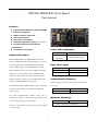
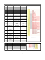
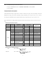
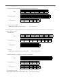
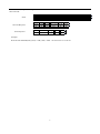
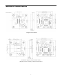
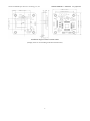
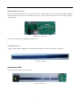
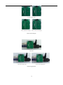
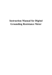
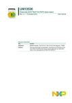
. Documnt Number: DRV060-HDMI-R01 Drive Board User manual Pre_Spec V0.2 For Products: SXGA060 SC - Full Color SXGA060 SW - Monochrome White Compatible with SVGA060 series Record of Revision Revision Revise Date Pre_Spec V0.1 Oct 14,2013 Pre_Spec V0.2 Oct 25,2013 Page Content Initial release . 2 1. Update general description 4 2. Add USB(Virtual COM) Communication protocol 8 3. Add Installation diagram with SVGA060 OLED 1 DRV060-HDMI-R01 Drive Board User manual Features High-Definition Multimedia Interface(HDMI) 1.4a features supported USB2.0 interface supported Hot Plug supported Low power consumption Industrial temperature grade(-40℃~+65℃) Automatic Gamma and temperture compersation Power and consumption Custom Re-configurable Input voltage General description Typical power consumption DRV060-HDMI-R01 is an HDMI input driver board DC 5V 800mW (Include display) mainly for SXGA060 Micro-OLED Display. Low power Input video signal consumption Decoder can automatically detects and converts TMDS signals into digital RGB 4:4:4 video Video signal TMDS data compatible with the 24-bit ITU-R BT.601 interface Input resistor 50Ω standard. It is also compatible with SVGA060 series. Output 1280×1024@60Hz Automatic identification of display supported and the Communication Interface default resolution is 1280×1024 for SXGA,800×600 for SVGA.EDID identification supported. USB2.0 supported. It works as a virtual COM based on CDC class. The SXGA060 Micro-OLED Display center is according to the drive board center , convenient for design and Interface USB (Virtual COM) optical system. COM Setting 9600bps/N/8/1 One USB communication interface allow user to Mechanic dimension configure all register of the Decoder and Display. User can re-configure the drive board flexible. Dimension (L×W) 31mm×31mm Refer to diagram of mechanism Low-noise, low-dropout DC/DC convertor can support 5V input voltage. 2 Interface and pin definition No. Name Function Voltage level 1,2 GND Power Ground 0V 3 USB_P USB Data+ 0~3.3V 4 USB_N USB Data- 0~3.3V 5,6 Vin Power Input 5V 7 HPD Hot Plug Detect 0/5V 8 HDMI_5V HDMI 5V Power 5V 9 GND Signal Ground 0V 10 HDMI_SDA DDC Data 0/5V 11 HDMI_SCL DDC Clock 0/5V 12 Reserve(N.C.) 13 HDMI_CEC 14 TMDS Clock- 15 TMDS Clock Shield Consumer Electronics Control 0/5V Clock- Input 0~3.3V Shield 0V 16 TMDS Clock+ Clock+ Input 0~3.3V 17 TMDS Data0- Data0 Input 0~3.3V Shield 0V 18 TMDS Data0 Shield 19 TMDS Data0+ Data0 Input 0~3.3V 20 TMDS Data1- Data1 Input 0~3.3V Shield 0V 21 TMDS Data1 Shield 22 TMDS Data1+ Data1 Input 0~3.3V 23 TMDS Data2- Data2 Input 0~3.3V HDMI&USB 24 25 TMDS Data2 Shield TMDS Data2+ Shield 0V Data2 Input 0~3.3V No. Name Function Voltage level 1 PGC Programming Clock 0/3.3V 2 PGD Programming Data 0/3.3V 3 VPP Programming Power 0/3.3V 4 GND Power Ground 0V 5 V3.3 3.3V Power Output 3.3V 3 J1 Note:1. It remarks the first pin as circle in the Connector. 2. The type of HDMI&USB connector is CABLINE-V (20347-025E-**) made by I-PEX. 3. J1 is no soldering. Communication description USB Communication interface support master controller to read/write the register value of the display, decoder and EEPROM. The change of the Decoder and Display will effect immediately, but when power down or reset, it will lost. The change of the EEPROM is equal to modify the default setting, will effect after power up in next time or reset. Every command must be sending in 600ms and total bytes must be less than 64 bytes, otherwise, will receive the error code. Communication mnemonic symbol Mnemonic Code(Hex) STX 02h Start symbol ETX 03h End symbol Err_Head F0h Start symbol error ACK 06h ACK symbol Err_End F1h End symbol error NAK 07h NAK symbol Err_CMD F2h CMD symbol error 00h Read soft version Err_DateLen F3h Data Length error 11h Read Display Err_Frame F4h Frame error 12h Read Decoder Err_FIFO F5h FIFO overflow 13h Read EEPROM Err_RxProc F6h CMD process error 21h Write Display Err_TimeOut F7h CMD timeout 22h Write Decoder Err_Waiting F8h CMD not finished 23h Write EEPROM Err_Unknow FFh Unknown CMD 41h Reset display 42h Reset decoder CMD 43h Signification Error Code Mnemonic Code(Hex) Open/Close temperature compensation 55h Reset 80h Resume factory setting Communication command formatting Send: STX + CMD +DataLen + Data + ETX DataLen Response: STX + CMD + DataLen + ACK/NAK + Data + ETX DataLen 4 Signification Command usage 1. Read command (All command are fixed in 6 bytes except read decoder) Send: STX 02 CMD 00/11/13 Length 03 Add0 00~FF Succeed Response: STX 02 CMD 00/11/13 Length 03~FF ACK 06 Data0 00~FF Error Response: STX 02 ErrCode F0~FF Length NAK 02 07 ETX 03 ReadLen 01~FF …… …… ETX 03 Datan 00~FF ETX 03 Read command examples: Read Display register from 00H to 0FH: 02 11 03 00 10 03 Since the decoder has eight independent data space which mapping in eight I2C slave addressee, it needs a different reading command as below: Read Decoder: Send: STX 02 CMD 12 Succeed Response: STX 02 CMD 12 Error Response: STX 02 ErrCode F0~FF Length 04 SlaveAddr XX Add0 00~FF Length SlaveAddr ACK 04~FF XX 06 Length NAK 02 07 Data0 00~FF ReadLen 01~FF …… …… ETX 03 Datan 00~FF ETX 03 Examples: Read decoder IOMAP (0x98) from 00H to 0FH: 02 12 04 98 00 10 03 2. Write Command (6 ≤ Total Bytes ≤ 64 except write decoder) Send: STX 02 CMD 21/23 Length Add0 Data0 03~3C 00~FF 00~FF Succeed Response: STX 02 CMD 21/23 Length ACK 02 06 ETX 03 Error Response: STX 02 ErrCode F0~FF Length NAK 02 07 ETX 03 …… …… Write command example: Write Display register (01H) = 41H, (19H) = A0H: 02 21 05 01 41 19 A0 03 5 Addn Datan 00~FF 00~FF ETX 03 To read decoder, a different writing command is needed: Write Decoder: Send: STX 02 CMD Length SlaveAddr Add0 Data0 22 04~3C XX 00~FF 00~FF Succeed Response: STX 02 CMD Length SlaveAddr ACK 22 03 XX 06 Error Response: STX 02 ErrCode F0~FF Length NAK 02 07 …… …… ETX 03 ETX 03 Example: Write decoder IOMAP(0x98) (01H) = 41H, (19H) = A0H: 02 22 06 98 01 41 19 A0 03 6 Addn Datan 00~FF 00~FF ETX 03 MECHANICAL CHARACTERISTICS Diagram of mechanism Installation diagram with SXGA060 OLED (Display center is according to the drive board center) 7 DRV060-HDMI-R01 Yunnan OLiGHTEK Opto-Electronic Technology Co.,Ltd. Installation diagram with SVGA060 OLED (Display center is not according to the drive board center) 8 Datasheet Pre_SpecV0.2 Accessories HDMI&USB Transfer Board A transfer board may be needed in order to facilitate the use of different users. This transfer board incorporates HDMI, USB signal and the 5V power into a CABLINE-V connector. It also support user to choose the power supply between USB and 5V-DC. HDMI&USB Transfer Board Note: User can purchase according to their actual use. CABLINE-V 25ways The type of the cable is CABLINE-V (20345-025T-02) made by I-PEX. It is necessary for all users. CABLINE-V 25Ways Accessories USE The cable itself can prevent reverse insertion. Physical Connection 9 No Power Supply Input Choose USB Power Supply Choose 5V-DC Power Supply Choose Power Supply Switch Off USB Power Supply Input 5V-DC Power Supply Input Practical application 10