1
NBD Manager
USER'S MANUAL (REV. 2.10)
RealTimeEvaluator
♦ Cautions
• Midas lab Inc. possesses all copyrights of NBD Manager (program and manual).
• This program and manual are protected by the Copyright Act and must not be copied, transcribed, or
revised without written permission from Midas lab Inc.
• You will be given a right to use this program on only one RTE-NBD2.
• All precautions are taken in producing this product. Midas lab Inc. and its distributors do not assume
any responsibility for the result of using this product.
• The contents of this program and manual are subject to change without notice.
♦ Trademarks
• MS-Windows, Windows, MS, and MS-DOS are trademarks of Microsoft Corporation.
The names of the other programs, systems, and CPUs mentioned in this document are the
trademarks of the respective manufacturers.
REVISION HISTORY
Date of enforcement
Revision
Chapter
Description
March 18, 1997
1.00
First edition
September 19, 1997
1.01
12.3
Clerical errors corrected, the description of
IDB/NBD connector, 25 pins.
September 19, 1997
1.02
6.2.5
The specification of the symfile command was
changed.
November 12, 2000
2.00
April 18, 2002
2.10
Some contents were deleted as a result of
changing configuration of the manual of the
NBD tool.
3.4.2, 3.4.4, 6
5.6
Real-time transmission was added.
Section "Real-Time Transmission File" was
added.
CONTENTS
1
INSTALLING/UNINSTALLING NBD Manager.......................................................................1
1.1
INSTALLING AND STARTING NBD Manager................................................................................1
1.2
UNINSTALLING NBD Manager ......................................................................................................1
1.3
OTHER PREPARATIONS ..............................................................................................................1
1.4
NUMERIC REPRESENTATION .....................................................................................................1
2
NBD Manager DISPLAY SCREEN STRUCTURE .................................................................2
3
MENU COMMANDS ...............................................................................................................3
3.1
File MENU ......................................................................................................................................3
3.1.1
Load ........................................................................................................................................3
3.1.2
Save As ...................................................................................................................................4
3.1.3
Load Symbol............................................................................................................................5
3.1.4
Exit ..........................................................................................................................................5
3.2
Edit MENU ......................................................................................................................................5
3.3
View MENU ....................................................................................................................................6
3.4
Monitor MENU ................................................................................................................................6
3.4.1
Start Refresh mode .................................................................................................................6
3.4.2
Start Monitoring .......................................................................................................................7
3.4.3
Stop Monitoring .......................................................................................................................7
3.4.4
Condition .................................................................................................................................8
3.4.5
Save Condition ........................................................................................................................9
3.4.6
Load Condition ......................................................................................................................10
3.4.7
Save Scan data .....................................................................................................................11
3.4.8
Previous Scan Page, Next Scan Page ..................................................................................12
3.4.9
Jump Page ............................................................................................................................12
3.5
Option MENU................................................................................................................................12
3.6
Window MENU .............................................................................................................................12
3.7
Help MENU...................................................................................................................................13
3.8
POP-UP MENU.............................................................................................................................13
4
TOOL BAR COMMANDS .....................................................................................................14
5
RAM MONITOR WINDOW ...................................................................................................15
5.1
START AND STOP OF RAM MONITOR ......................................................................................15
5.2
RAM MONITOR RESULT DISPLAY .............................................................................................16
5.3
MONITOR CHANNEL SETTING ..................................................................................................17
5.4
DELETING MONITOR CHANNELS..............................................................................................18
5.5
MOVING MONITOR CHANNEL POSITIONS ...............................................................................18
5.6
REAL-TIME TRANSMISSION FILE ..............................................................................................18
5.6.1
File Name ..............................................................................................................................18
5.6.2
5.7
File Format ............................................................................................................................19
RAM MONITOR CONDITIONS.....................................................................................................21
5.7.1
Starting and Ending Conditions .............................................................................................21
5.7.2
RAM Monitor Starting Condition ............................................................................................21
5.7.3
Scan Starting Condition.........................................................................................................22
5.7.4
RAM Monitor Ending Condition .............................................................................................22
6
REAL-TIME TRANSMISSION ..............................................................................................23
7
COMMAND WINDOW ..........................................................................................................23
8
CAUTION ..............................................................................................................................23
NBD Manager
1
USER'S MANUAL (REV.2.10)
INSTALLING/UNINSTALLING NBD Manager
1.1 INSTALLING AND STARTING NBD Manager
NBD Manager can be started by copying the files in the disk supplied as an accessory to a
folder and executing NBDMAN.EXE. The supplied files are:
NBDMAN.EXE
Main program (NBD Manager)
NBDMANTP.HLP
Help file
1.2 UNINSTALLING NBD Manager
To uninstall NBD Manager, delete all the files copied to the folder. Because the NBD Manager
program does not create any file that contains default values and a registry, NBD Manager can be
uninstalled simply by deleting the files that were copied when it was installed.
In uninstall, it is recommended that additional files (such as a monitor condition setting file, a
resulting data file, etc.), which will have been created during the program run, be deleted if they are
unnecessary.
1.3 OTHER PREPARATIONS
The following preparations must be made to start NBD Manager.
* Refer to "RTE for WIN32 Installation Manual" and install :rte4win32 from the CD-ROM
supplied as an accessory.
* Refer to "KIT-xxxx-NBD User's Manual" of the CPU used, and set the hardware and initialize
rte4win32.
* Start NBD Manager with power supplied to both the NBD tool and target system.
1.4 NUMERIC REPRESENTATION
The numeric inputs to NBD Manager are handled as hexadecimal numbers.
Hexadecimal
values beginning with A to F must be preceded by 0x or 0 for entry. Hexadecimal values beginning
with 0 to 9 can be entered as is. Inputs other than the above are regarded as being symbols. Any
symbol information is replaced by the associated numeric value. If a symbol has no associated
value, it results in an input error.
<Example>
1234,01234,0x1234,0FF8000,0xFF8000
1
NBD Manager
2
USER'S MANUAL (REV.2.10)
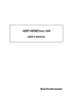
NBD Manager DISPLAY SCREEN STRUCTURE
Menu bar
Tool bar
RAM monitor window:
Command window:
On this window, the result of the
This window allows the user to
RAM monitor and the set states of
enter a character string of a
the channels are displayed. This
command and have the result
window also enables the setting of
displayed.
a channel.
2
NBD Manager
3
USER'S MANUAL (REV.2.10)
MENU COMMANDS
The menu commands that are present on the menu bar are described below.
3.1 File MENU
3.1.1 Load
The Load command reads objects from a file and writes them into memory.
Enter the start address for writing
Select the data size
the file contents into memory.
for accessing
Select when the file
is HEX format.
memory.
Object data in either a binary format file or a HEX format file may be read.
Only the S format can be used as the HEX format.
Only the space defined by the
specifications of the NBD interface of the CPU is valid. If writing is not supported by the CPU, this
function cannot be used.
3
NBD Manager
USER'S MANUAL (REV.2.10)
3.1.2 Save As
The Save As command reads the contents of memory and writes them into a file. Writing into a
file is performed the only in the binary format.
Enter the start address in memory
from which the contents are to be
read.
Select the data size
for accessing
memory.
Enter the range of the memory
in units of bytes.
The contents of memory may be read from the built-in ROM space (including a tuning RAM) and
the built-in RAM space and written into a file.
However, only the space defined by the
specifications of the NBD interface of the CPU is valid.
4
NBD Manager
USER'S MANUAL (REV.2.10)
3.1.3 Load Symbol
The Load Symbol command reads the symbol information from a file. The file format shall be
ELF format in which the GHS tool output is performed. The symbols to be read are limited to
global symbols.
3.1.4 Exit
The Exit command terminates NBD Manager.
A prompt appears, asking if you want to exit NBD Manager.
3.2 Edit MENU
These commands can be used only from the line command window.
The copying or pasting of character strings is performed as desired.
5
NBD Manager
USER'S MANUAL (REV.2.10)
3.3 View MENU
Choose whether the tool bar is displayed.
3.4 Monitor MENU
This menu contains the commands used to control the RAM monitor.
3.4.1 Start Refresh mode
The Start Refresh mode command causes the RAM monitor to start in refresh mode. The RAM
monitor scans the memory at the refresh time interval that has been set by the Condition
command. The scanned data is displayed in the RAM monitor window. The refresh time is the
only valid condition set by the Condition command. This mode continues until the Stop Monitoring
command is executed.
6
NBD Manager
USER'S MANUAL (REV.2.10)
3.4.2 Start Monitoring
The Start Monitoring command causes the RAM monitor to start in normal mode. Start, scan,
and end are performed as set by the Condition command. The display of the result is performed
only when the end condition is satisfied. If the end condition is Free Run, however, the result is
displayed when the Stop Monitoring command is executed. The hourglass cursor appears to
indicate that the RAM monitor is running.
If real-time transmission is specified by the Condition command, a dialog box that is used to
specify a file to which real-time transmission data is to be saved is displayed.
When a file name has been specified, RAM monitor is started, and real-time transmission data is
saved to the file. For the file name, see Section 5.6.
3.4.3 Stop Monitoring
The Stop Monitoring command stops the running RAM monitor. When the RAM monitor stops,
the monitor scanned data, if present, is displayed in the RAM monitor window.
7
NBD Manager
USER'S MANUAL (REV.2.10)
3.4.4 Condition
The Condition command allows the user to set the RAM monitor conditions. The set conditions
become valid when the RAM monitor starts. For details of each condition, see Section 5.7.
Select the start condition.
Select the scan condition.
Select the end condition.
Enter a value for the timer
if you selected Timer as
If you selected User Event,
the scan condition.
this button is used to set the
In refresh mode, enter a value for
user event condition. When
the time interval for refreshing
you click this button, an
the display on the screen.
event dialog box, like that
shown below, will appear.
Check if real-time transmission is executed.
Enter the address of an
event.
Select the event condition.
8
NBD Manager
USER'S MANUAL (REV.2.10)
3.4.5 Save Condition
The Save Condition command saves all the conditions for the RAM monitor into a file.
When you select Save Condition, a dialog box like that shown below will appear. You may
assign an arbitrary name to the file into which the RAM monitor conditions are saved.
The contents saved into the file are the conditions set by the Condition command and the
conditions for channels set in the RAM monitor window. If a symbol name has been set for a
channel, then the symbol name will be saved.
9
NBD Manager
USER'S MANUAL (REV.2.10)
3.4.6 Load Condition
The Load Condition command reads the RAM monitor conditions from the file.
The file to be specified must be one in which the RAM monitor conditions were saved by
the Save Condition command.
The RAM monitor conditions cannot be read during the execution of the RAM monitor. When
the conditions are read, the most recent monitor scanned data is erased.
If a symbol is applied to the channel condition, "unknown" may be displayed in the address
column. This is because the symbol information has not been saved into the file or because the
symbol has no associated value. In such a case, the symbol information should be read, using the
Load Symbol command in the File menu. If there is a channel whose address is unknown, the
RAM monitor cannot start.
10
NBD Manager
USER'S MANUAL (REV.2.10)
3.4.7 Save Scan data
The Save Scan data command saves the monitor scanned data into a file.
Check this button if you want to specify the pages to be
saved. Specify the start page and the end page.
Check this button if the currently displayed page is to be saved.
Check this button if all the pages are to be saved.
Data is saved to a file in the text format of the CSV format, with each item delimited by a comma
from the others, so that the data can be edited by using an editor. The data is saved in the
following format:
Number of channels, "symbol of channel 1 address", ..., "symbol of channel n address"
Number of channels, "channel 1 address", "channel 2 address", ..., "channel n address"
Number of page number, channel 1 data, channel 2 data, ..., channel n data
:
:
Each line is saved as
one page.
[Example] Example of three channels
3,"data1","","data2",
* "" if there is no symbol.
3,"FFFFC204","FFFFC210","FFFFC214",
1,22136,22136,305419896,
2,22136,22136,305419896,
:
Data that cannot be monitored will not be output. On the last page, channel data may be lost
because it cannot be monitored.
11
NBD Manager
USER'S MANUAL (REV.2.10)
3.4.8 Previous Scan Page, Next Scan Page
The Previous Scan Page command displays the page that precedes the currently displayed
page. The Next Scan Page displays the page that follows the currently displayed page.
3.4.9 Jump Page
The Jump Page command allows the user to choose the page to be displayed.
3.5 Option MENU
Select the mode in which the memory data will be
displayed on the RAM monitor window.
The Font command is used to select the font of the display on the RAM monitor window and the
line command window.
3.6 Window MENU
Select the window display.
Changes the active window.
12
NBD Manager
USER'S MANUAL (REV.2.10)
3.7 Help MENU
At present, the RTE-NBD/Win version is displayed.
3.8 POP-UP MENU
In the RAM monitor window, right-clicking causes the pop-up menu shown below to appear.
See the sections on setting and deleting channels in
the RAM monitor window.
See the section on the Option menu.
See the section on the Monitor menu.
13
NBD Manager
4
USER'S MANUAL (REV.2.10)
TOOL BAR COMMANDS
Eleven icon buttons are provided on the tool bar. They are associated with the RAM monitorrelated commands of the menu commands.
Clicking an icon button selects the associated
command.
By clicking this icon button, objects are read from a file and written into memory. This
corresponds to the Load... command in the File menu.
By clicking this icon button, the contents of memory are read and written into a file.
This corresponds to the Save As... command in the File menu.
By clicking this icon button, symbol information is read from a file. This corresponds
to the Load Symbol command in the File menu.
By clicking this icon button, the RAM monitor starts in refresh mode. This
corresponds to the Start Refresh mode command in the Monitor menu.
By clicking this icon button, the RAM monitor starts in scan mode. This corresponds
to the Start Monitoring command in the Monitor menu.
By clicking this icon button, the RAM monitor stops. This corresponds to the Stop
Monitoring command in the Monitor menu.
By clicking this icon button, the monitor scanned data on the previous page is
displayed. This corresponds to the Previous Scan Page command in the Monitor
menu.
By clicking this icon button, the monitor scanned data on the next page is displayed.
This corresponds to the Next Scan Page command in the Monitor menu.
By clicking this icon button, the RAM monitor conditions are read from a file. This
corresponds to the Load Condition... command in the Monitor menu.
By clicking this icon button, the RAM monitor conditions are saved into a file. This
corresponds to the Save Condition... command in the Monitor menu.
By clicking this icon button, you may set the RAM monitor conditions. This
corresponds to the Condition... command in the Monitor menu.
By clicking this icon button, the result of the monitor is saved into a file. This
corresponds to the Save Scan data... command in the Monitor menu.
14
NBD Manager
5
USER'S MANUAL (REV.2.10)
RAM MONITOR WINDOW
In the RAM monitor window, the user may set the RAM monitor channels. The result of the
monitor is displayed in the data column.
Cursor
No.:
Point:
Address:
Data:
Size:
Log:
Info:
Displays the channel number. The channels are used in order, starting from the
lowest number.
Displays the symbol entered by the user at channel setting.
Address to be monitored.
Displays the data resulting from execution of the RAM monitor. Display is made in
the specified display mode. If the width of the display has been altered, the lower
portion of the data is displayed.
Data size.
Indicates whether hardware output has been set.
Indicates whether a timeout occurred during the execution of the RAM monitor.
5.1 START AND STOP OF RAM MONITOR
There are two RAM monitor modes:
• Refresh mode
In refresh mode, the RAM monitor scans the memory at a certain interval and displays each
scanned data. The RAM monitor repeats scan and display until it has been stopped.
• Scan mode
In scan mode, the RAM monitor scans the memory, provided the specified condition is
satisfied. When the end condition is satisfied, the RAM monitor is automatically stopped and
the result is displayed.
Monitor start in refresh mode
1. Set the refresh time interval, using the Condition command in the Monitor menu.
2. Set the channels to be monitored.
3. Start the RAM monitor by executing the Start Refresh mode command in the Monitor menu.
4. Stop the RAM monitor by executing the Stop Monitoring command in the Monitor menu.
15
NBD Manager
USER'S MANUAL (REV.2.10)
Monitor start in scan mode
1. Set the start, scan, and end conditions, using the Condition command in the Monitor menu.
2. Set the channels to be monitored.
3. Start the RAM monitor by executing the Start Monitoring command in the Monitor menu.
4. The RAM monitor is stopped upon the completion of the monitor. If the end condition is Free
Run, however, it is never satisfied.
Thus, stop the RAM monitor by executing the Stop
Monitoring command in the Monitor menu.
When the monitor starts, the displayed last monitor result is erased and no longer displayed.
Caution
The correct result of RAM monitor may not be obtained unless the CPU is under
execution. If any other tool (such as the IDB tool or ICE) is connected to the
CPU, execute the CPU and then start monitoring.
5.2 RAM MONITOR RESULT DISPLAY
The result of the monitor is displayed in the data column of the RAM monitor window. The
resulting data is displayed, according to the size. The display in the data column may be in
hexadecimal, signed decimal, unsigned decimal, or binary.
(Selection can be made from the
Hexadecimal Display, Signed Decimal Display, Unsigned Decimal Display, and Binary Display
commands in the Option menu and the pop-up menu which is invoked by right-clicking.)
Currently displayed page number
Total number of pages
Monitor result data
Timeout information
The timeout information includes the following three:
TOV
Timeout occurs during scanning.
RST
Reset occurs during scanning.
RTOV
Timeout occurs during real-time transmission.
16
NBD Manager
USER'S MANUAL (REV.2.10)
5.3 MONITOR CHANNEL SETTING
The monitor channel setting includes addition (a new channel is set) and alteration.
To add a new channel, double-click a new row position below the last set channel number or
click the Add Point command in the pop-up menu. Then, a dialog box like that shown below will
appear.
Choose Add when adding the channel
after its address has been set.
Choose End to exit from the channel
setting dialog.
Check Log out to get the hardware output of the monitor result.
Channels can be added successively until the RAM monitor window has no more empty channel
positions and you click the End button. A new channel is added after the last set channel.
To change a channel that has already been set, double-click the position of the channel that you
want to alter or click the Edit Point command in the pop-up menu. Then, a dialog box like that
shown below will appear.
Click OK to save the change.
Click Cancel to cancel the
change.
Choose Delete to delete
the channel.
Addition and/or alteration causes all the data of the currently displayed monitor result to be
erased.
17
NBD Manager
USER'S MANUAL (REV.2.10)
5.4 DELETING MONITOR CHANNELS
To delete all the monitor channels, choose the All Delete command in the pop-up menu. To
delete an optional channel, select a channel to delete (click the channel position with the mouse)
and choose the Delete command in the pop-up menu. While holding down the CTRL key, you may
select and delete multiple channels. The dialog box for channel alteration may be used to delete
channels.
As channel deletion is performed, all the data for the currently displayed monitor result is erased.
5.5 MOVING MONITOR CHANNEL POSITIONS
Set channels may be moved to another position. After selecting a channel to move, move the
cursor to a desired position while holding down the left button of the mouse. When the button is
released, the selected channel moves to that position. The channel is inserted immediately before
the cursor position.
While holding down the CTRL key, you may select and move multiple
channels.
As channel positions are moved, all the data for the currently displayed monitor result is erased.
5.6 REAL-TIME TRANSMISSION FILE
5.6.1 File Name
The name of the real-time transmission file is the file name specified at the starting of RAM
monitor to which character string "-xxxxxx" suffixed is added. "xxxxxx" is a 6-digit decimal number
string that starts from "000000" and is incremented.
The extension is CSV.
Therefore, the
extension of the specified file name is ignored. For example, if file name "sample.dat" is specified,
file name "sample-000000.CSV" is created.
The file is created so that its maximum size does not exceed 512 KB. If it does exceed 512 KB,
the file name is incremented as described above.
If "-xxxxxx" is suffixed to the specified file name, as "test-000005.CSV", "-xxxxxx" is ignored, and
file names are created sequentially, starting from "test-000000.CSV".
18
NBD Manager
USER'S MANUAL (REV.2.10)
5.6.2 File Format
The file is in the text format and CSV format with each item delimited by a comma from the
others.
Header information is recorded at the beginning of the file, followed by real-time transmission
data.
The header information is in the following format, with six pieces of information recorded. All
these pieces of information are recorded to the file.
• Date
0,"DATE", "date and time"
The date and time on the personal computer at which the file are created is recorded.
"date and time" is a character string of ="YYYY-MM-DD hh:mm:ss.xxx", where YYYY indicates
the year; MM, the month; DD, the day; hh, the time in 24-hour system; mm, the minutes; ss,
the seconds; and xxx, the milliseconds.
Example: 0,"DATE",="2002-04-19 10:43:10.445"
• Scan time interval
0,"SCAN_INTERVAL", "time"
If a timer is used as the scan start condition, the set value of the timer is recorded. "time" is
in µs. 0 (zero) is recorded if a timer is not used as the scan start condition.
Example: 0,"SCAN_INTERVAL",100
• Number of channels
0,"CHANNEL_NUM", "number of channels"
The number of channels per scan is recorded.
Example: 0,"CHANNEL_NUM",3
• Symbol
0,"SYMBOL", "ch1 symbol", "ch2 symbol", …
"chx symbol" is character string information. A symbol indicating the address of each channel
is recorded.
If there is no symbol at the corresponding address, NULL ("") is recorded.
Example: 0,"SYMBOL","data1","data2",""
• Address
0,"ADDRESS", "ch1 address", "ch2 address", …
"chx address" is character string information. The address of each channel is recorded as a
hexadecimal character string.
Example: 0,"ADDRESS","FFFFC204","FFFFC210","FFFFC214"
• Size
0,"DATA_SIZE", "ch1 size", "ch2 size", …
"chx size" is character string information. The data size of each channel is recorded.
"BYTE" is recorded if the channel size is 8 bits. "HWORD" is recorded if it is 16 bits, and
"WORD" is recorded if it is 32 bits.
Example: 0,"DATA_SIZE","HWORD","WORD","BYTE"
Data is in the following format:
"scan number" ,, "ch1 data", "ch2 data", …, "flag"
19
NBD Manager
USER'S MANUAL (REV.2.10)
"scan number" is a numeric value.
The data information at the beginning of the file is
sequentially incremented from 1. "scan number" returns to 1 again if the file size increases and
the file is replaced with a new one.
"chn data" is a signed decimal value. It is recorded in accordance with the data size of each
channel.
"flag" is character string information. Each of the following character strings is recorded if the
status it indicates occurs. If two or more statuses occur at the same time, only one is recorded in
accordance with the following priority (the status indicated at the top takes the highest priority).
"x:TRANS_OVF"
Real-time host transmission was not performed in time between the data
of channel x and the preceding data, and data that has not been recorded
exists.
"SCAN_OVF"
The start condition of the current scan was satisfied before the previous
scanning is completed, and data that was not recorded by the previous
scanning has existed.
"RESET"
The CPU was reset after the first scanning was started and before the
current scanning is started, and data that was not recorded by the
previous scanning or scanning that was not recorded (the scan start
condition was satisfied during reset) has existed.
""
Without above status.
Example: Here is an example of a data field where three channels are specified.
1,,-65536,1914364691,43,""
2,,-131071,1914364691,,""
3,,,1914364691,23,"2:TRANS_OVF"
4,,-196606,1914364691,11,""
:
20
NBD Manager
USER'S MANUAL (REV.2.10)
5.7 RAM MONITOR CONDITIONS
This chapter explains the conditions that can be set in connection with the RAM monitor.
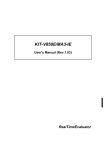
5.7.1 Starting and Ending Conditions
There are three items for which conditions can be set.
Item
Description
RAM monitor start
When the specified RAM monitor starting condition is satisfied, the RAM monitor circuit is
activated and waits for the scan starting condition to occur.
(Start Condition)
Scan start
When the specified scan starting condition is satisfied while the RAM monitor circuit is active,
the RAM circuit performs one scanning cycle and records the scan results.
(Scan Condition)
RAM monitor end
When the specified RAM monitor ending condition is satisfied while the RAM monitor circuit is
active, the RAM circuit is deactivated and stops data recording.
(End Condition)
The scan starting condition is satisfied.Note
RAM monitor starting condition
The scan starting
condition is satisfied.
RAM monitor end
The scan starting
condition is satisfied.
The scan starting
condition is satisfied.
The scan starting
condition is satisfied.
RAM monitor signal
NBD bus
CH0
CH1
CH2
CHn
Note When the interval timer is specified as the scan starting condition, the first
scan starts immediately after the RAM monitor is started, rather than waiting
for the scan starting condition to occur.
5.7.2 RAM Monitor Starting Condition
The following table shows the conditions that can be set in relation to the activation of the RAM
monitor circuit. Only one of the conditions can be specified at a time.
Condition
Forced start
Description
(Force)
The RAM monitor circuit is activated immediately after the command
is input.
User event
Match detection trigger of the NBD event detection function
(User Event)
External input
Positive Edge
When the external input signal (RAMMONITOR_EXT) goes low or
high
Negative Edge
21
NBD Manager
USER'S MANUAL (REV.2.10)
5.7.3 Scan Starting Condition
The following table shows the conditions that can be set in relation to the start of the scan. Only
one of the conditions can be specified at a time. Also, if a break occurs, the scan stops as soon as
the bus cycle being scanned comes to an end, regardless of which condition is specified.
Condition
Description
(Timer)
The scan is started at specified intervals, ranging from 4 to 2147385345 µs.
Upon the start of the RAM monitor, the first scan is started immediately. The
second and subsequent scans are executed at specified intervals.
User event
Match detection trigger of the NBD event detection function
Interval timer
(User Event)
When the external input signal (RAMMONITOR_EXT) goes low or high
External input
Positive Edge
Negative Edge
The scan is halted
temporarily.
A break occurs.
RUN
RUN signal
NBD bus
CH0
CH1
CHn
CHn+1
CHm
One scan cycle
5.7.4 RAM Monitor Ending Condition
The following table shows the conditions that can be set in relation to the end of the RAM
monitor. Only one of the conditions can be specified at a time.
Condition
User event
Description
Match detection trigger of the NBD event detection function
(User Event)
External input
Positive Edge
When the external input signal (RAMMONITOR_EXT) goes
low or high
Negative Edge
One shot
(One Shot)
Full memory
(Data Full)
The RAM monitor ends upon the completion of one scan
cycle.
The RAM monitor ends when the record memory becomes
full. Unlike the other conditions, if this condition is satisfied,
the monitor stops, even if in the middle of the scan.
22
NBD Manager
6
USER'S MANUAL (REV.2.10)
REAL-TIME TRANSMISSION
The function to transmit data during RAM monitor to the host and to save it is called a real-time
transmission function. To execute real-time transmission, check "Realtime Transmission" on the
Condition dialog box, and check Free Run as End Condition (see Section 3.4.4).
The quantity of the data that can be transmitted to the host is limited. The upper-limit value is
shown below for your reference, but this value is not guaranteed. The data quantity substantially
varies depending on the environment of the host.
If an overflow occurs, either decrease the
number of points or increase Interval Time.
Recommended host environment
OS:
Windows 2000
CPU:
Pentium 2 550 MHz or higher
Host interface: RTE-PCIIF (PCI-IF)
Quantity of data that can be transmitted (guideline)
Number of points ÷ Interval Time (ms) < 64 (k word/s)
Example:
64 points * 1 ms
16 points * 250 µs
<Caution>
The following environment is necessary for using this function.
Rte4Win32:
Use Ver5.06 or later.
NBD Manager: Use Ver1.40 or later.
NBD tool:
7
Use RTE-NBD2.
COMMAND WINDOW
The line command defined for each CPU can be used on the command window. For the line
command that can be used, refer to the manual of the kit corresponding to the CPU used.
8
CAUTION
Some CPUs do not support some functions of NBD Manager.
NBD Manager displays the
functions that cannot be used in gray on the selection menu. For details, refer to the manual of the
kit.
23
NBD Manager
USER'S MANUAL (REV.2.10)
Memo
NBD Manager USER'S MANUAL
M674MNL01
Midas lab
24