1
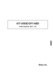
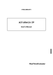
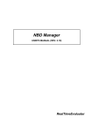
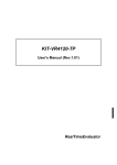
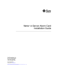
ADP-V850E/xxx-144
USER'S MANUAL
RealTimeEvaluator
REVISION HISTORY
Rev.1.00
February 22, 2002
Official first edition
1
CONTENTS
1. OVERVIEW ................................................................................................................................................................3
2. APPEARANCE...........................................................................................................................................................4
3. NBD-IF CONNECTOR ...............................................................................................................................................5
4. PRECAUTIONS FOR USE........................................................................................................................................6
5. CONNECTING THIS PRODUCT TO USER SYSTEM ............................................................................................7
2
1. OVERVIEW
The ADP-V850E/xxx-144 is an adapter that is to be attached to the tip of an in-circuit emulator for NEC's
RISC microcontroller V850E/xxx, to convert a 208-pin product into a 144-pin one.
This product is supplied with the following accessories:
1. ADP-V850E/xxx-144 main enclosure (with 208-pin plug)
:
1
2. RTE for Win32 setup disk
:
1
3. User's Manual (this document)
:
1
4. 144-pin TQPACK set
:
1
3
2. APPEARANCE
The appearance of the ADP-V850E/xxx-144 is shown below.
1pin (208/144)
53
11
NBD-IF
53
28
Top view
26.5
RTQPLUG-208SDF-P
TQS-144SDF
35
29
TQS-144SDW
19
TQP-144SD
1.125
22 × 22
25.5 × 25.5
Unit : mm
Side view
4
3. NBD-IF CONNECTOR
The following table shows the specifications of the NBD-IF connector. An RTE-NBD2 16-pin connector
can be directly connected.
Pin No.
Signal name
I/O
Description
1
NBD_TRG-
O
Connected to TRIG_DBG pin of CPU in ICE
2
NBD_VCC
--
Connected to 3.3 V
3
no use
--
Not used
4
GND
--
Connected to ground
5
NBD_CLK
I
Connected to CLK_DBG pin of CPU in ICE
6
GND
--
Connected to ground
7
NBD_SYNC-
I
Connected to SYNC pin of CPU in ICE
8
GND
--
Connected to ground
9
NBD_DATA0
I/O
Connected to AD0_DBG pin of CPU in ICE
10
GND
--
Connected to ground
11
NBD_DATA1
I/O
Connected to AD1_DBG pin of CPU in ICE
12
GND
--
Connected to ground
13
NBD_DATA2
I/O
Connected to AD2_DBG pin of CPU in ICE
14
NBD_DATA3
I/O
Connected to AD3_DBG pin of CPU in ICE
15
MODE_DBG
I
Connected to MODE_NBD pin of CPU in ICE
16
NBD_RESETO-
O
Connected to RESET0_DBG pin of CPU in ICE
Note:
1. "I/O" in the above table indicates the direction of input and output viewed from this adapter.
Pin configuration
15 13 11
9
7
5
3
1
16 14 12 10
8
6
4
2
Pin configuration of NBD-IF connector
Applicable connector:
16-pin cable side:
XG4M-1630-T manufactured by Omron Corporation, or equivalent
16-pin board side:
XG4C-1631 manufactured by Omron Corporation
5
4. PRECAUTIONS FOR USE
Note the following points when using this adapter.
1. Checking emulator version
The version must be 5 or later.
Check the version on the sticker on the rear panel of the emulator.
2. Setting DIP switch of emulator
* Set Nos. 2, 3, and 4 of SW1 as shown in the following table to set the operating frequency to
32 MHz .
CLKHALF(4)
PLLSEL2(3)
PLLSEL1(2)
Operating frequency
ON
OFF
OFF
(48 MHz)
ON
OFF
ON
(72 MHz)
ON
ON
OFF
(80 MHz)
ON
ON
ON
64 MHz
OFF
ON
ON
32 MHz
* Set No. 8 (CLKINT) of SW1 to ON (internal clock) only. Setting it to OFF is prohibited.
3. Installing RTE for Win32
Install the CD supplied as an accessory.
For upgrading, use version 5.06 or later.
4. Initializing RTE for Win32
Start up ChkRTE2.exe and initialize RTE for Win32 with the following parameters.
RTE:
V850E/yyy-IE or V850E/zzz-IE
I/F-1:
<< Specify the interface card to be used.
I/F-2:
<< Specify an IO port as necessary.
Specifying RTE:
V850E/yyy-IE :
Select this when the internal ROM is a 384K version.
V850E/zzz-IE :
Select this when the internal ROM is a 256K version.
5. Mounting to emulator
Mount the adapter to the emulator so that pin 1 of the adapter matches the position of the
corresponding pin of the e mulator.
If the adapter is mounted in a wrong direction, it may cause malfunctioning.
6. Others
When the adapter is connected to the emulator, the noise margin may drop as compared with when
the emulator alone is used. Observe the points to be noted of t he emulator and use the adapter and
emulator in the best conditions. For the same reason, do not use any other package conversion
adapter in combination.
6
5. CONNECTING THIS PRODUCT TO USER SYSTEM
When connecting the user system, refer to the technical document of the PACK supplied as an
accessory. After mounting the adapter to the user system, connect the adapter and emulator, in that order,
as illustrated below.
Tip of RTE-V850E/xxx-IE
RTQPLUG-206SDF-P
TQS-144SDF (for protection)
TQS-144SDW (with guide)
To GND
Be sure to use TQS-144SDW
(with guides). Otherwise, signal
lines will be short-circuited.
TQP-144SD
Soldered
User system
7