1
VIDEO MONITOR
USER’S MANUAL
SOF-842 User’s Manual
DOC-124
Rev. 1.6
Copyright © 2008
All Rights Reserved
MED Associates, Inc.
P.O. Box 319
St. Albans, Vermont 05478
www.med-associates.com
MED ASSOCIATES INC.
VIDEO MONITOR
- ii -
MED ASSOCIATES INC.
VIDEO MONITOR
TABLE OF CONTENTS
Chapter 1 ........................................................................................................... 1
Introduction ..................................................................................................... 1
General Computer Environment........................................................................ 1
Chapter 2 ........................................................................................................... 2
Interface Reference ........................................................................................... 2
System Settings Dialog ................................................................................... 2
Add/Delete Annotation Set ............................................................................ 13
Time Lapse Scheduler................................................................................... 13
Camera Window........................................................................................... 17
Playback Window ......................................................................................... 20
Chapter 3 ......................................................................................................... 22
Using Video Monitor......................................................................................... 22
Configuring Cameras .................................................................................... 23
Troubleshooting........................................................................................... 24
Trigger from MED-PC.................................................................................... 26
Chapter 4 ......................................................................................................... 31
Hardware, Driver and Software Installation ......................................................... 31
Installing Video Monitor Software ................................................................... 31
Hardware Installation ................................................................................... 34
Installing the FireWire Camera Driver ............................................................. 35
- iii -
MED ASSOCIATES INC.
VIDEO MONITOR
- iv -
MED ASSOCIATES INC.
VIDEO MONITOR
CHAPTER 1
Introduction
The MED Associates Video Monitor System is a video display/recording and computer
system designed to allow researchers to monitor animal behavior during experimentation.
Cameras can be mounted inside animal cubicles, giving the researcher a clear view of the
animal's activities without disturbing the animal. A variety of cameras and lenses are
available to satisfy most viewing requirements. Video Monitoring System integrates with
MED-PC ® , allowing MED-PC to control the starting and stopping of the video, and
allowing MED-PC to insert comments into the saved video files. For example, when an
animal receives a reward, MED-PC can insert the text "Reward pellet given" into the
video file, allowing for accurate timing of when events happen inside a video file. Video
Monitoring System supports a variety of camera modes, resolution, and frame rates.
General Computer Environment
•
•
•
•
•
3.4GHz Processor
1GB RAM
Windows TM 2000 SP4, XP or Vista (32-bit only)
Fire Wire Card
Fire Wire Camera(s)
- 1 -
MED ASSOCIATES INC.
VIDEO MONITOR
CHAPTER 2
Interface Reference
This chapter describes the important dialogs and screens of the Video Monitor Software.
For a discussion of how to use Video Monitor, refer to the Using Video Monitor section
of this manual.
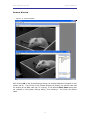
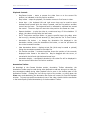
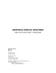
System Settings Dialog
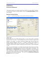
Figure 2-1 - System Settings Dialog (showing optional and advanced features)
Camera Tree
At the upper left of the System Settings dialog is a tree control similar to Windows
Explorer’s folder view pane. The tree displays two levels of hardware configured and
attached to the system. The upper level shows FireWire cards, and the lower level
displays cameras attached to that card. To expand a FireWire card to display its
connected cameras, double click with the mouse or press the keyboard “+” key. To
collapse a card and hide its cameras, double click with the mouse or press the keyboard
“-“ key.
Clicking the left mouse button on a FireWire card will cause most fields on the System
Settings Dialog to be disabled, because they display camera specific information. The
Cameras On and Cameras Max fields, however, are applicable at the FireWire card
level. Clicking on a camera will cause the remaining fields on the dialog to display
information unique to that camera. If a camera is plugged in and does not appear in the
tree, first be sure the card is expanded. Then refer to the Installing & Configuring
Hardware section of this manual.
- 2 -
MED ASSOCIATES INC.
VIDEO MONITOR
Renaming a Camera
To rename a camera, select the camera in the tree. Either click on the camera again
with the left mouse button, or use the right mouse button to bring up the context menu
and choose Rename.
On/Off
If the On/Off field is checked (On), the camera selected in the Camera Tree control will
be shown when the System Settings dialog is closed. An image stream from each “On”
camera will be displayed in its own window when the OK button is pressed.
Save Video
If the Save Video field is checked, the camera selected in the Camera Tree control will
have video recorded to disk. If the Save Video field is checked, the On/Off field must
also be filled to record video. The video file will be saved under the filename displayed
in the File Name field, and in the directory in the Saved File Folder field.
Cameras On (Current Card) / Max Cameras (Current Card)
Cameras On (Current Card) displays the number of cameras that are turned on for the
FireWire card currently active in the Camera Tree control. When the OK button is
pressed, and the System Settings dialog is closed, each “on” camera will have it’s video
stream displayed.
Cameras Max (Current Card) shows the maximum number of
cameras that may be activated on that FireWire card. Cameras Max (Current Card) will
never be greater than the number of cameras successfully attached to the FireWire card
selected in the tree control.
Cameras On (Computer) / Max Cameras (Computer)
The Cameras On (Computer) displays the number of cameras “on” for the entire
system. For systems with only one FireWire card installed, this number will be the same
as the Cameras On (Current Card) field. Max Cameras (Computer) displays the
cumulative total of the Cameras Max (Current Card) values from each FireWire card.
Saved File Folder / Browse
Video or snapshots for the camera selected in the tree control will be saved in this
directory. Use the Browse button or type in a valid directory name.
File Name / Use Default
Video files will be saved with this filename. The keywords “_Date” and “_Time”
(without quotes) will be expanded to the date and time that the video was started. The
date will be in format DDMonYYYY, time as HH-MM-SS. For example, if the File Name
field is “RatCage1_Date_Time.wmv”, and the video starts at 4:13:22 PM on September
23, 2006, the saved file will be called “RatCage1_23Sep2006_16-13-22.wmv”.
Press the Use Default button to have a filename automatically created in the format:
CameraName_Date_Time. In the example above, the camera name is “RatCage1”.
- 3 -
MED ASSOCIATES INC.
VIDEO MONITOR
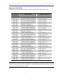
Supported Video Modes
Video Monitor supports the following video formats and associated frame rates:
PIXEL
RESOLUTION
DESCRIPTION
160 x 120
YUV (4:4:4) Mode (24 bit/pixel)
7.5, 15, 30
320 x 240
YUV (4:4:2) Mode (16 bit/pixel)
3.75, 7.5, 15, 30
640 x 480
YUV (4:1:1) Mode (12 bit/pixel)
3.75, 7.5, 15, 30
640 x 480
YUV (4:2:2) Mode (16 bit/pixel)
3.75, 7.5, 15, 30
640 X 480
RGB Mode (24bit/pixel)
3.75, 7.5, 15, 30
640 X 480
Y (Mono) Mode (8bit/pixel)
3.75, 7.5, 15, 30, 60
640 X 480
Y (Mono16) Mode (16bit/pixel)
3.75, 7.5, 15, 30
800 X 600
YUV (4:2:2) Mode (16bit/pixel)
3.75, 7.5, 15, 30
800 X 600
RGB Mode (24bit/pixel)
7.5, 15
800 X 600
Y (Mono) Mode (8bit/pixel)
7.5, 15, 30, 60
1024 X 768
YUV (4:2:2) Mode (16bit/pixel)
1.875, 3.75, 7.5, 15
1024 X 768
RGB Mode (24bit/pixel)
1.875, 3.75, 7.5
1024 X 768
Y (Mono) Mode (8bit/pixel)
1.875, 3.75, 7.5, 15, 30
800 X 600
Y (Mono16) Mode (16bit/pixel)
3.75, 7.5, 15, 30
1024 X 768
Y (Mono16) Mode (16bit/pixel)
1.875, 3.75, 7.5, 15
1280 X 960
YUV (4:2:2) Mode (16bit/pixel)
1.875, 3.75, 7.5
1280 X 960
RGB Mode (24bit/pixel)
1.875, 3.75, 7.5, 15
1280 X 960
Y (Mono) Mode (8bit/pixel)
1.875, 3.75, 7.5, 15
1600 X 1200
YUV (4:2:2) Mode (16bit/pixel)
1.875, 3.75, 7.5
1600 X 1200
RGB Mode (24bit/pixel)
1.875, 3.75
1600 X 1200
Y (Mono) Mode (8bit/pixel)
1.875, 3.75, 7.5, 15
1280 X 960
Y (Mono16) Mode (16bit/pixel)
1.875, 3.75, 7.5
1600X 1200
Y (Mono16) Mode (16bit/pixel)
1.875, 3.75, 7.5
640 X 480
Y (Mono) Mode (8 bit/pixel)
100
480 X 256
Y (Mono) Mode (8 bit/pixel)
250
FRAME RATES (fps)
NOTE: All cameras do not provide all modes supported by Video Monitor. The specific
video formats and frame rates available will vary depending on which camera(s) you are
using with your Video Monitor system.
- 4 -
MED ASSOCIATES INC.
VIDEO MONITOR
Save Video Trigger
The trigger mechanism for saving video can be manually controlled, or from MED-PC, or
(on some cameras) a TTL pulse.
•
Manual: video will begin recording when the OK button is pressed on the System
Settings dialog, if the Save Video checkbox is filled.
•
Remote: the save video trigger will be sent from MED-PC script language. When
the System Settings OK button is pressed, the camera’s video stream will be
shown in a window with “Waiting for remote trigger…” in the title bar. Video
saving will start when commanded by MED-PC. For more details, refer to the
section: Trigger from MED-PC.
Optional Save Video Trigger
•
TTL Input Line 1: video saving starts when the camera’s TTL input line 1 goes
high. As with the Remote setting, the camera’s video stream will be shown in a
window titled “Waiting for remote trigger…” when the System Settings dialog OK
button is pressed. TTL High is 3.5 to 5 VDC; TTL Low is 0.0 to 0.4 VDC. All
cameras do not support this feature. Triggering video recording via TTL Input
directly to the camera is an optional accessory to Video Monitor.
NOTE: Do not confuse the Save Video Trigger described here with the “Trigger” option
in the Features section of the System Settings dialog. The Features section Trigger
refers to externally controlling each frame’s capture via a TTL pulse on input line 0. See
the Camera Features section below for more on the frame rate Trigger setting.
Annotation Set
When recording video or playing back a video using the Video Monitor player, text can be
added to the video file and stored in the resulting .wmv file. When the video is played
back, the text will appear as closed captions, with the timestamp and text. This text is
added to the video file using the Annotation Toolbar in the playback and recorder
windows.
The Annotation Toolbar will show a set of text strings defined as an
Annotation Set. To choose which Annotation Set to show in the Annotation Toolbar with
the camera stream during recording, select the desired set in the Annotation Set list box.
To add or delete Annotation Sets, choose “Add / Delete Annotation Set” from the list box.
For more information on creating Annotation Sets, see section “Add/Delete Annotation
Set”.
Frame Rate
Based on the Video Mode selected, various frame rates are available. The frame rates
listed are in units of frames per second. A higher frame rate will require more processor
resources and hard drive space. It is important to note that if the frame rate setting is
higher than 60 fps, it may be necessary to save the video as uncompressed.
If a hardware frame trigger is used (Features section, Trigger option, Feature On
checked) the trigger rate must be entered. The Frame Rate list box will be disabled, and
an edit box labeled “Ext. Trig. Rate” will be shown. Enter the trigger rate in frames per
second so the playback window knows which speed to play the video.
- 5 -
MED ASSOCIATES INC.
VIDEO MONITOR
Uncompressed Video
Clicking this check box disables the compression routine while saving to disk. This will
yield very large files, and should only be used for short duration videos.
The
uncompressed video option is intended for high (>60 fps) frame rate videos, where the
compression algorithm might not be fast enough to keep up with the incoming video.
Bit Rate
When saving video to disk, the video stream data is compressed to conserve storage
space. The recommended video compression ratio is 120:1. This is an approximate
value; the requirements for video quality and disk space may differ. To calculate the bit
rate for your video format and frame rate, use the following formula:
width * height * bits per pixel * frames per second / 1024 / 120 = bitrate (kbps)
Where “ width” and “ height” are the frame size in pixels, and “ bits per pixel” is essentially
the color resolution of the image format. “ Frames per second” is the camera recording
rate. “1024” is the number of bits per kilobit, and “120” is the recommended data
acquisition to storage ratio.
For example: a 640 * 480 pixel, 16 bpp format image at 30 frames per second should
use a bit rate of 1200 kbps.
640 * 480 * 16 * 30 / 1024 / 120 = 1200 kbps
If the bit rate is too low, the processor will not be able to keep up with the video stream,
and video frames will be dropped. For this reason, it is recommended that the default bit
rate or higher be used.
Disk Space Remaining
The amount of hard drive space available in the “Saved File Folder” drive will be
displayed in hours : minutes : seconds format.
Fit to Screen
Fill this checkbox if it is desired to have the video image fill the camera window client
area. If this checkbox is clear, the image will be shown in the recorded format. For
example, a 640 * 480 image would be shown as 640 pixels wide by 480 pixels high,
regardless of the size of the camera window. When viewing multiple tiled cameras at
once, Fit to Screen is useful, sacrificing proper image spatial relation in favor of seeing
the entire video image.
Record For
To record video for a specific amount of time, fill the Record For check box, and enter
the video length in seconds, minutes, or hours. The “Save Video” check box should also
be filled.
- 6 -
MED ASSOCIATES INC.
VIDEO MONITOR
Time Lapse Scheduler
To activate the Time Lapse Scheduler section, fill the Time Lapse Scheduler check box.
The Time Lapse Scheduler provides the ability to have videos or still shots recorded at
specific intervals. For more information on using the Time Lapse Scheduler, see the
“Time Lapse Scheduler” section below.
Complexity (Advanced Configuration)
Complexity is only shown with the command line switch /advconfig specified at program
startup. Valid values are 1, 2, 3, or 4. This value specifies the level of compression
algorithm complexity. A higher level of complexity will demand more processor usage,
and yield a better-looking video image. For most purposes, level 1 is appropriate .
Key Frame (Advanced Configuration)
Key Frame is only shown with the command line switch /advconfig specified at program
startup. The Key Frame value is maximum number of seconds between key frames in the
saved video (*.wmv) file. Normally this value is eight seconds.
File Quality (Advanced Configuration)
File Quality is only shown with the command line switch /advconfig specified at
program startup. Valid values are integers, 0-100. Similar to Complexity, a higher value
will require more processor resources and yield a better-looking video image. Default
value is 50.
- 7 -
MED ASSOCIATES INC.
VIDEO MONITOR
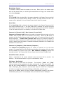
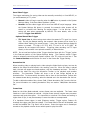
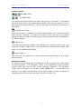
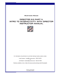
Camera Features
The camera features section allows the user to alter imaging components. The options
vary by camera model. The camera features may also be adjusted during runtime by
clicking the Camera Features icon in the camera window toolbar.
Figure 2-2 - Camera Features Icon and Dialog
As a general rule, set all features to Automatic, if available, as a first step in creating a
sharp, clear picture. During live video playback of a typical camera in a multi-camera
setup, adjust one feature at a time. Once satisfied, if all cameras are the same make
and model, press the Apply to All Cameras button. Some fine-tuning of individual
cameras may still be necessary due to slight camera, lighting, environment, and subject
differences.
- 8 -
MED ASSOCIATES INC.
VIDEO MONITOR
Most video cameras support the following features:
•
Brightness – adjusts the black level of the camera.
•
Auto Exposure – allows the camera to control exposure time.
•
Sharpness – affects the clarity of detail in an image.
•
White Balance – calibrates a camera's color response to take into account different
“color temperatures” of light (i.e., fluorescent light is greenish; sunlight, more blue;
incandescent light, yellowish). This calibration allows the camera to define what the
color white is under any of these various lighting conditions.
•
Saturation - the saturation of a color is the degree to which the color departs from
neutral gray of the same brightness. An attribute of perceived color, or the
percentage of hue in a color. Saturated colors are called vivid, strong, or deep.
•
Gamma - allows application of a non-linear response curve. One thing that a user
may notice when adjusting the gamma is a grayish film in the resulting image (i.e.
image appears washed out). This is generally a result of the Gamma being set too
high.
•
Shutter – somewhat camera dependent, but generally sets the time between images
captured. Some camera types implement this differently, and hardware differences
at the digital image sensor level mean that some cameras can create clearer images
at faster refresh rates than others.
NOTE: for cameras operating under format 7 (partial image format / high speed
frame rates of greater than 60 fps), the Shutter setting will affect the frame rate.
For this reason, the Shutter control setting is automatically controlled by the Video
Monitor software when operating in format 7 and using an external hardware trigger
(TTL pulse). Otherwise, adjusting the shutter rate while saving video would result in
a variable frame rate with unpredictable playback.
•
Gain – a multiplier for the camera sensor signal output.
•
Trigger – some cameras allow the frame capture timing to be externally controlled.
In normal operating mode (Features Trigger off) the camera is set to operate at a
particular frame rate, for example, 30 fps (frames per second). The camera then is
responsible for capturing images at that rate. With the Features Trigger on, the
camera waits for an externally generated TTL pulse on its input line 0 to signal the
capture of each frame.
NOTE: The Features section “Trigger” is much different than the options in the Save
Video Trigger section. Those settings refer to the source of the save video start
command, where the Features Trigger refers to the source of the frame exposure
command.
“Polarity” is camera dependent, but refers to whether the camera exposure is
triggered on the rising or falling edge of the TTL trigger signal. MOST cameras use a
“low active” configuration, meaning that when the Polarity checkbox is cleared
(default), the camera will trigger on the falling edge of the TTL pulse. Conversely, if
the checkbox is filled, the exposure will start on the rising TLL pulse edge.
- 9 -
MED ASSOCIATES INC.
VIDEO MONITOR
When using the Trigger feature, Video Monitor will automatically control the shutter
rate, and the Shutter option will not be shown on the Features dialog when launched
from the camera window’s toolbar. The reason is if the shutter rate was slowed
beyond the exposure cycle time, the desired frame rate could not be achieved.
Currently, only 640 x 480 resolution, with a maximum of 104 frames per second
external trigger rate is supported. Minimum external trigger rate is 1 frame per 15
minutes. TTL “High” voltage is 3.5 – 5 VDC. TTL “Low” voltage is 0 – 0.4 VDC. The
frame trigger channel is input port 0.
- 10 -
MED ASSOCIATES INC.
VIDEO MONITOR
Apply To All Cameras
Once all of a camera’s features and settings are customized, these settings can be copied
to other cameras. This is a time saving feature when working with multiple cameras of
the same make and model, which are operating in similar lighting situations, and
observing similar subjects. The other cameras in the camera tree will copy the following
settings:
•
•
•
•
•
•
•
•
•
•
•
•
•
•
Camera On/Off
Save On/Off
Save Directory (but NOT file name)
Bit Rate (if Use Default Bit Rate is ON, default is calculated)
Frame Rate (fps) (if available)
Fit To Screen
Complexity
File Quality
Key Frame Spacing
Record Time
Use Remote Saving
Format / Mode (if available on destination camera)
Time Lapse Scheduler
o On/Off
o Video / Snapshot
o Action at Time 0 / Delay 1 st Action
o Every X Time
o Experiment Length Time
Feature Settings (if available on destination camera)
o Brightness - Auto (on/off) / Value (number)
o Exposure - Auto / Value
o Sharpness - Auto / Value
o White Balance - Auto / Value 1 / Value 2
o Hue - Auto / Value
o Saturation - Auto / Value
o Gamma - Auto / Value
o Shutter - Auto / Value
o Gain – Auto / Value
o Iris – Auto / Value
o Focus – Auto / Value
o Temperature – Auto / Value 1 / Value 2
o Trigger – On / Polarity / Mode / Parameter
o Zoom – Auto / Value
o Pan – Auto / Value
o Tilt – Auto / Value
- 11 -
MED ASSOCIATES INC.
VIDEO MONITOR
Defaults
Click this button to load the default values for this camera. The default values cover the
fields:
•
•
•
•
•
•
•
•
•
•
•
•
•
•
•
•
•
•
•
•
•
•
•
•
•
•
Format
Mode
Frame Rate (fps)
Brightness - Auto / Value
Exposure - Auto / Value
Sharpness - Auto / Value
White Balance - Auto / Value1 / Value2
Hue - Auto / Value
Saturation - Auto / Value
Gamma - Auto / Value
Shutter - Auto / Value
Gain - Auto / Value
Iris - Auto / Value
Focus - Auto / Value
Temperature - Auto / Value1 / Value2
Trigger - On / Polarity / Mode / Parameter
Zoom - Auto / Value
Pan - Auto / Value
Tilt - Auto / Value
Fit To Screen
File Quality
Bit Rate
Key Frame Spacing
Complexity
Use Remote Saving
Time Lapse Scheduler Settings
- 12 -
MED ASSOCIATES INC.
VIDEO MONITOR
Add/Delete Annotation Set
Figure 2-3 - Add/Delete Annotation Set
When recording or playing a video, the annotation toolbar can be used to add text notes
to the video file. These annotations can be viewed using Media Player by turning on
Closed Captioning. Groups of annotations are called Annotation Sets. To create a new
annotation set, or delete an existing set, select Add/Delete Annotation Set from the
Annotation Set list box on the System Settings dialog. The dialog above will appear.
To create a new set, type the name in the New Annotation Set edit field. If you wish
to initially populate the text fields of the annotation set with those of an existing set,
check the Copy Annotations from Selected Set field, and highlight a field in the
Current Annotation Sets list box.
To delete an Annotation Set, select the set in the Current Annotation Sets list box,
and click the Delete Set button.
For information on adding and removing text strings to the Annotation Set, see the
“Annotation Toolbar” section later in this manual.
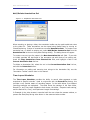
Time Lapse Scheduler
The Time Lapse Scheduler provides the ability to record video segments or take
snapshots at specific intervals. Used in conjunction with the Record For feature, this
provides a very flexible means of recording images. In the table below, five different
recording examples are explained. The table shows the settings of the Save Video,
Record For, and Time Lapse Scheduler check boxes, the Video / Snapshot radio setting,
and the Record For, Every, and Experiment Length time settings.
In Example A, the video stream is recorded until the user closes the camera window, or
presses the Start/Stop Saving video button in the camera window toolbar.
- 13 -
MED ASSOCIATES INC.
VIDEO MONITOR
Figure 2-4 - Example A
In Example B, a video is recorded for 30 minutes.
Figure 2-5 - Example B
- 14 -
MED ASSOCIATES INC.
VIDEO MONITOR
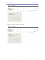
In Example C, a 5-minute video segment is recorded every 30 minutes for 2.1 hours.
The result is a single video file (*.wmv) with 5-minute video segments separated by a
blue screen, and each segment start is annotated. There will be five video segments in
the video file if Action at Time 0 is selected (as shown in Figure 2-6), or four video
segments if Delay 1 st action is selected.
Figure 2-6 - Example C
In Example D, a snapshot is taken every 30 minutes for 2 hours. The snapshots will be
saved as bitmap (*.bmp) files, and named as “CameraName_####.bmp”, where
“CameraName” is the name of the camera in the tree control and #### is the lowest
available number.
Figure 2-7 - Example D
- 15 -
MED ASSOCIATES INC.
VIDEO MONITOR
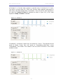
In Example E, video is recorded for 75 minutes, and snapshots are taken every 30
minutes for 2 hours. And as in Examples C and D, the number of snapshots taken in
Example E will be five if Action at Time 0 is selected (as shown in Figure 2-8), or four if
Delay 1 st Action is selected.
Figure 2-8 - Example E
- 16 -
MED ASSOCIATES INC.
VIDEO MONITOR
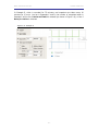
Camera Window
Figure 2-9 - Camera Window
After clicking OK on the System Settings dialog, the Camera Windows will appear for any
camera set On. The title bar of the Camera Window will display the camera name and
the location of the WMV video file if it is saving. If the camera’s Save Video setting was
not checked on the System Settings dialog, “Not recording…” will follow the camera
name.
- 17 -
MED ASSOCIATES INC.
VIDEO MONITOR
Toolbar Controls
Save On Toolbar
Save Off Toolbar
The camera window has several icons under the title bar in the toolbar. If the camera
was set to Save Video in the System Settings dialog, there are three buttons. The first
button starts and stops the saving. There are two buttons if the camera was not set to
Save Video.
Stop/Start Saving Video
When the OK button is pressed on the System Settings dialog, any camera set to Save
Video will start recording. So pressing this button for the first time on any Camera
Window will stop the video from saving, but the live video stream will still be displayed in
the Camera Window.
Snapshot Tool
The button that looks like a camera is the Snapshot tool. Press this button, and a still
image will be saved in BMP format in the same directory specified as the “Saved Video
Folder” on the System Settings dialog.
Camera Features
The right-most icon accesses the Camera Features dialog described in the System
Settings section.
Annotation Toolbar
For cameras that are saving video, the Annotation Toolbar will appear at the right side of
the Camera Window. The Annotation Toolbar is also applicable using the Playback
Window, which may allow for more precise annotation placement. The Annotation
Toolbar can be turned off via the main window’s View menu. The Annotation Set
specified in the System Settings dialog will be initially loaded, but may be changed by
pulling down the list box at the upper right, as shown in Figure 2-10.
- 18 -
MED ASSOCIATES INC.
VIDEO MONITOR
Figure 2-10 - Changing the Annotation Set
The name of the currently loaded Annotation Set is in the title bar of the annotation
window (“Default” in Figure 2-10).
To annotate a video means to post descriptive text at a particular time, which will be
seen as Closed Captioning during video playback. An annotation may be placed in a
video during playback or recording.
Annotations may be applied using the mouse or keyboard. With the mouse, double click
the text in the Annotation Bar with the left mouse button. Using the keyboard, press the
indicated key combination, that is, hold down the Alt key then press the key specified
next to the annotation.
To add an annotation to an Annotation Set, type the text in the box to the left of the
annotation set pull-down list box, then press <Enter>.
To delete an annotation from a Annotation Set, highlight the behavior, and press the
<DEL> or <Delete> key on your keyboard.
To create or delete an entire Annotation Set, refer to the “Add/Delete Annotation Set”
section earlier in this manual.
- 19 -
MED ASSOCIATES INC.
VIDEO MONITOR
Playback Window
To play a recorded video, select Open from the File menu, and choose the WMV file.
The video will be opened in a Playback Window.
Figure 2-11 - Playback Window
The Playback Window plays saved videos, shows annotations, and adds new annotations.
The video may be run at regular speed, or stepped through frame-by-frame. During
playback, annotations will be displayed below the video. Annotations added during
playback will be displayed in the lower pane of the Annotation toolbar.
- 20 -
MED ASSOCIATES INC.
VIDEO MONITOR
Playback Controls
•
Play/Pause button – starts or pauses the video from or at the current file
position, as indicated in the file position scrollbar.
•
Stop button – stops the playback, file location moves to first frame in video.
•
Arrow keys – the keyboard left and right arrow keys can be used to move
backward and forward while the video is paused, and the file position scrollbar
control has the focus. The keyboard focus is indicated by a dotted line around
the control. The arrow keys will move the video position one frame at a time.
•
Repeat checkbox – to play the video in a continuous loop, fill this checkbox. If
empty, the video will stop after the last frame.
•
Go To Time button and time fields – to jump to specific time in the video, enter
the hours (H), minutes (M) and seconds (S), then press the “Go To Time” button.
•
Annotation Set button – to change the Annotation Set displayed in the
Annotation toolbar, press the Annotation Set button, or use the pull-down list
box in the Annotation toolbar.
•
View Annotations button – displays a text file (which may be saved or printed)
listing the annotations posted to the video file.
•
File Position scrollbar – horizontal scrollbar shows the position of the currently
displayed video frame in the video file. May be dragged with the cursor, or
moved with the left and right keyboard arrow keys.
•
Annotation display – annotations attached to the video file will be displayed in
the text control below the File Position scrollbar.
Annotation Toolbar
As described in the Camera Window section, Annotation Toolbar subsection, the
Annotation Toolbar may be used during video playback to add text strings to a video clip.
Any annotations added during video playback can be seen in the bottom pane of the
Annotation Toolbar. Clicking the X at the top right of the toolbar, or pulling down the
View menu and deselecting the Annotation Bar option will remove it from the Playback
window. To jump to a specific annotation’s time in the video, double click the annotation
in the bottom pane (Posted Annotations) of the Annotation Toolbar.
- 21 -
MED ASSOCIATES INC.
VIDEO MONITOR
CHAPTER 3
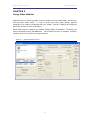
Using Video Monitor
Video Monitor is a flexible program; it can be used to view live video feeds, record video,
and play back saved videos. To view or record live video, Video Monitor requires
camera(s) to be properly configured with your system. See the “Installing & Configuring
Hardware” section for more information.
When Video Monitor is started, the System Settings dialog is displayed. The dialog can
also be accessed through the File menu. Use this dialog to turn on cameras, configure
cameras, and set the video file storage locations.
Figure 3-1 - System Settings Screen
- 22 -
MED ASSOCIATES INC.
VIDEO MONITOR
Configuring Cameras
A FireWire card has 314 Megabits per second maximum throughput.
calculated as:
Throughput is
Throughput = width * height * bit rate * frame rate
Where width is the Screen Resolution Width (pixels), height is Screen Resolution Height
(pixels), bit rate is Stream Bit Rate (bits per pixel or “bpp”), and frame rate is the
video recording rate (frames per second or “fps”).
For example, a camera running in YUV 4:1:1 mode at 30 frames per second would use
640 pixels * 480 pixels * 12 bpp * 30 fps = 110,592,000 bits/sec. So only two cameras
running at YUV 4:1:1, 30 fps could be run per FireWire card. To achieve more
simultaneous video streams, use a less demanding video mode or a slower frame rate.
Remember that there are tradeoffs while setting up the Video Monitor system. Due to
the data bandwidth constraints of the FireWire card(s), the computer PCI bus, and hard
drive access restrictions, cameras may not operate properly at the highest frame rates, in
the largest resolutions.
As a general rule, begin with the cameras set at the lowest acceptable resolution, slowest
frame rate, and the default (or higher) bit rate. Then, make adjustments one field at a
time until the optimum image, file quality and file size are achieved.
If the computer’s processing and data transfer resources are exceeded, image frames will
be lost or “dropped”. If the video appears jerky, or the frame rate is uneven, first stop
all other non-essential windows programs. Be especially aware of any scheduled events,
such as a virus scan or disk defrag, that may occur during the experiment and affect the
videos. Then, use a lower frame rate, or a smaller camera resolution, or a higher bit rate
to achieve a smooth video stream.
- 23 -
MED ASSOCIATES INC.
VIDEO MONITOR
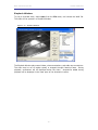
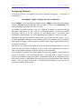
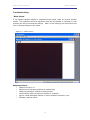
Troubleshooting
“Black Screen”
If the Camera Window displays a completely black image, there are several possible
causes. The problem could be an equipment issue with the camera or connection, or the
problem lies within the camera’s settings. Refer to the following lists and ensure that
none of these problems are the cause.
Figure 3-2 - “Black Screen”
Equipment Issues
•
•
•
•
•
•
Camera lens cap is on.
Camera lens not properly attached to camera body.
Camera lens aperture rotated to closed position.
Loose FireWire cable connection at camera or computer.
Light in Sound Attenuated Cubicle (or other closed environment) is out.
Computer requires reboot.
- 24 -
MED ASSOCIATES INC.
VIDEO MONITOR
Camera Settings
•
•
•
•
•
Brightness level not set to automatic, and level is too low.
Trigger set “On”. This is the Camera Features Trigger, which is waiting for a
pulse on the TTL switch signal line to begin frame exposure; not the remote
trigger to begin recording from MED-PC.
Auto Exposure level not set to automatic, and level is too low.
Gain level not set to automatic, and level is too low.
Shutter level not set to automatic, and level is too low.
Resolution
If all possible equipment issues have been eliminated, try setting all the camera features
to “Automatic”, if offered. Be sure the camera feature setting for Trigger is “Off”. If the
image is still black, use the “Defaults” button on the System Settings dialog to set
everything to a “base” state.
Troubleshooting Video Capture
Video Monitor software is a computationally intensive system, and as such the physical
limitations of the computer resources are stretched. Depending on the type of camera
and settings being used, it is possible that the limits of the system could be exceeded. If
this is the case, the following error messages may appear;
Failed to register the camera. GetLastError returned (#). This message indicates
the system is unable to handle the current system settings for the number of cameras
being used. Also, this error message may be seen if an unexpected error (such as a
system crash) occurred while a camera was operating, and the camera was not properly
shut down. Disconnect and reconnect the FireWire cable to the camera and restart Video
Monitor to resolve.
Error. Out of memory. The computer is not fast enough or does not have
enough memory to save this video. This message usually results from attempting to
save video (usually uncompressed) data to disk faster than the computer can manage.
If either message is encountered, stop saving video and lower the frame rate. At a
resolution of 640 x 480 most current systems can handle no more than fifteen frames per
second with four cameras saving simultaneously, or two cameras at thirty frames per
second. The options will depend upon which camera style is included with the system.
Also try avoiding uncompressed video, increasing the bit rate (which will lower processor
requirements for video compression) or decreasing camera resolution below 640 x 480.
In the event that the system “hangs”, the most likely cause is a large backlog of hard
disk operations. Either utilize Windows Task Manager to stop the program, or left-click
on the Save Video button to stop saving. It may take a moment for the system to stop
saving the video. If Task Manager is used to stop the program it is suggested that the
system be restarted before continuing.
If the limits of the system are approached it is possible that frames will be “dropped” if
the computer falls too far behind. A symptom of this is inconsistency between the
displayed Duration of camera time and the timestamp on Annotations. The system has
- 25 -
MED ASSOCIATES INC.
VIDEO MONITOR
been designed so that if this occurs, the saved video file will be of the correct duration
and the Annotations file will also be correct.
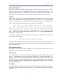
Trigger from MED-PC
A MED-PC program can start and stop recording video by issuing commands to Video
Monitor. The MED-PC code may be run on a different computer than the Video Monitor
software, as long as the MED-PC computer can “see” the Video Monitor computer on the
network. It is recommended, however, that MED-PC and Video Monitor run on the same
computer.
There are four steps in the MED-PC procedure to save video with Video Monitor.
1. Open communication channel with Video Monitor.
2. Send command to begin recording.
3. Send command to end recording.
4. Close communication channel.
In detail:
1. To open the communication channel with Video Monitor, the MED-PC procedure
issues a ConnectToVM or ConnectToVMEx command.
ConnectToVM - takes two parameters: the Video Monitor computer name, and the
camera name.
Example: ConnectToVM(‘testxp’, ‘SAC1’) opens communication with Video
Monitor running on a computer called ‘testxp’, and a camera named ‘SAC1’.
ConnectToVMEx - provides error reporting back to MED-PC. ConnectToVMEx takes
four parameters. In addition to the computer and camera name, ConnectToVMEx
takes the MPCGlobal pointer, and BOX identifier. The MPCGlobal pointer is a pointer
to MED-PC’s internal data structures. BOX identifies which box is running the
procedure. The MPCGlobal and BOX parameters provide Video Monitor a method to
report errors back to MED-PC.
Example: ConnectToVMEx(MG, BOX, '.', 'CamA') opens communication with
Video Monitor running on the same computer as MED-PC (‘.’), and a camera named
“CamA”. The MPCGlobal pointer is always referenced as “MG” and the Box identifier
should always be referenced as “BOX”.
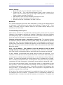
Note in the ConnectToVMEx example the Video Monitor program is run on the same
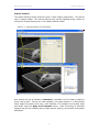
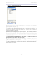
computer as MED-PC, and therefore the computer name is “.”. To find the Video
Monitor computer name when using a two-computer setup, go to the Start menu,
then Control Panel, open the System dialog, and then click the Computer Name
tab. The computer name is the text before the first period on the “Full computer
name” line. In the screen shot below, the computer name is “testxp”. Leave off the
domain information (.car.inavt.us) when specifying this computer in the Med State
Notation code.
- 26 -
MED ASSOCIATES INC.
VIDEO MONITOR
Figure 3-3 – Finding Computer Name
When using the extended ConnectToVMEx connection protocol, connection errors
are reported back to MED-PC. In the status bar of MED-PC, to the right of the date
and time, the message “ERRORS! CHECK LOG!” will appear. Pull down the MED-PC
View menu, and choose Display Log. The error log will have the Video Monitor
communication error at or near the end of the file. ConnectToVM does not provide
error reporting, ConnectToVMEx does provide error reporting.
2. The second step in the MED-PC code is to issue a StartSavingEvent command using
the WriteEventVM function.
WriteEventVM - takes four parameters: the computer and camera names, as well
as the event type, and any text to appear in the closed captioned portion of the
recorded video.
The possible event types are:
StartSavingEvent,
PauseSavingEvent, StopSavingEvent, or GeneralEvent. Start, Pause, and Stop
are self-explanatory, use the GeneralEvent when you want the text specified in the
fourth parameter to appear as a video annotation with no other actions.
Example: WriteEventVM('.', 'Sac4', StartSavingEvent, 'Video Start') tells
Video Monitor to start saving on camera named “Sac4”. The “.” means Video Monitor
is running on the same computer as MED-PC. The text “Video Start” will appear in
the annotation portion of the recorded video.
Now that the camera has been started, begin your experiment commands. When
done with the experiment and you are ready to stop recording video, the third and
fourth commands should be issued.
- 27 -
MED ASSOCIATES INC.
VIDEO MONITOR
3. Stop the video by writing a StopSavingEvent command using WriteEventVM.
Example: WriteEventVM('.', 'Sac4', StopSavingEvent, 'Video Stop') tells
Video Monitor to stop saving video on camera “Sac4”. The text “Video Stop” will
appear in the annotation area of the saved video.
4. Close MED-PC to Video Monitor communication channel with DisconnectVM.
Example:
DisconnectVM('.', 'Sac4') commands Video Monitor to close its
communication channel with MED-PC.
Basic MED-PC Triggering Example
Following is a basic example of triggering a camera using MED-PC code.
Start Trans IV
In Trans IV, create a new file and type in the Med State Notation below.
1. Pull down the Trans IV File menu and click New.
2. Enter program in Med State Notation.
State 1 in the code below opens a
communication channel with a camera named ‘Sac4’. The ‘.’ indicates Video Monitor
is running on the same computer as the MED-PC software. To trigger Video Monitor
running on a networked computer other than the computer running this Med State
Notation, specify the computer name in place of ‘.’ below. State 2 starts saving
video. State 3 stops the saving after 60 seconds. State 4 closes the communication
channel.
S.S.1,
S1,
1": ~ConnectToVM('.', 'Sac4');~ ---> S2
S2,
2": ~WriteEventVM('.', 'Sac4', StartSavingEvent, 'Start Video');~ ---> S3
S3,
60": ~WriteEventVM('.', 'Sac4', StopSavingEvent, 'Stop Video');~ ---> S4
S4,
1": ~DisconnectVM('.', 'Sac4');~ ---> STOPKILL
3. Pull down the Trans IV File menu and click Save As….
Name the file
VideoTest.MPC.
4. Open the Trans IV Translation menu, and choose Translate and Compile. Be
sure MED-PC is NOT running before compiling.
5. In the Specify Files to Translate dialog, select the VideoTest.MPC file and click the
Make button. Click the OK button to translate and compile the program.
6. Exit Trans IV.
- 28 -
MED ASSOCIATES INC.
VIDEO MONITOR
Start Video Monitor
At the Video Monitor System Settings dialog, perform the following steps.
1. Select camera Sac4 in the tree control.
2. Fill checkboxes for On and Save.
3. Select Remote Trigger.
4. Click OK.
The System Settings dialog will close and a window with camera Sac4’s video stream will
be displayed. The title bar will read, “Waiting for remote trigger…”. Video Monitor is
now properly configured to receive commands from MED-PC.
Start MED-PC
1. If MED-PC is running on a machine with no connected MED-PC hardware, select No
at the warning dialog to run in Emulation mode.
2. If the Wizard starts, click Close to exit.
3. Pull down the MED-PC File menu, and choose Open Session.
4. In the Procedure combo box, select VideoTest (or name used in Step 3 of Trans IV
section above).
5. Select Box 1 as the only box to load.
6. Press OK.
7. Press Close.
The camera window title in Video Monitor will change from “Waiting for remote trigger…”
to “CAMERA: Sac4 SAVING TO: XXXXX”, where XXXXX is the location specified in the
System Settings dialog Saved File Folder and File Name fields.
Extended MED-PC Triggering Example
For a more detailed MED-PC to Video Monitor communication example, see the
Video.MPC procedure that ships with Video Monitor. This procedure uses the extended
connection method ConnectToVMEx. The procedure also calls another useful function:
GetIfaceStatus, to alter the course of the MED-PC procedure execution in case of an
error during communication start up.
Video.MPC opens communication with MED-PC using the extended connection method,
and checks the status of the communication before continuing. If the communication is
OK, a 10 second video is recorded. If the communication fails, an error will be reported
to the MED-PC session log, and the Video.MPC procedure exits.
\ Copyright (C) 2008 MED Associates, All rights reserved.
\
\
\
\
\
\
\
\
\
Video.mpc
Assigns MED_VM_Interface.dll Connection constants (defined in VM_Iface.hed)
to local array "Q".
Attempts connection with VideoMonitor over LAN (Domain or Workgroup).
If it does not connect, it retries every 1/10 second.
If it connects with Video Monitor, a Video is recorded for 10 seconds, then
the connection is terminated.
- 29 -
MED ASSOCIATES INC.
VIDEO MONITOR
\ List Working Variables Here
\ Q() = Array holds MED-VM Interface Connections Status States
\ Q(0) = Unconnected
\ Q(1) = Good Connection
\ Q(2) = FAILED Connection
\
\ X = Video Monitor Connection Status
DIM Q = 2
\***************************************************
\
MAIN PROGRAM
\***************************************************
S.S.1,
S1,
1": ~Q[0] := UNCONNECTED;
Q[1] := CONNECT_OK;
Q[2] := CONNECT_FAIL;
ConnectToVMEx(MG, BOX, '.', 'Cam');~;
SHOW 3,Unconnected =,Q(0), 4,Connected =,Q(1), 5,Failure =,Q(2) ---> S2
S2,
\ Attempt connection with VideoMonitor
\ X is Interface Status Value from MED_VM_Interface.dll
0.1": ~X := GetIfaceStatus();~;
SHOW 2,Status:,X;
IF X = Q(0) [@NotConnected, @Next]
@NotConnected: SHOW 1,Not Connected,0 ---> S2
@Next: IF X = Q(1) [@Connected, @Next]
@Connected: SHOW 1,Connected OK,1 ---> S3
@Next: IF X = Q(2) [@Failed, @Unknown]
@Failed: SHOW 1,Connection Failed,0 ---> S6
@Unknown: SHOW 1,Unknown State,0 ---> S6
S3,
\ Send command to Start Saving Data
1": ~WriteEventVM('.', 'Cam', StartSavingEvent, 'StartEvent');~ ---> S4
S4,
\ Send command to Stop Saving Data
10": ~WriteEventVM('.', 'Cam', StopSavingEvent, 'StopEvent');~ ---> S5
S5,
\ Disconnect from VideoMonitor
0.01": ~DisconnectVM('.', 'Cam');~ ---> S6
S6,
0.01":
---> STOPKILL
- 30 -
MED ASSOCIATES INC.
VIDEO MONITOR
CHAPTER 4
Hardware, Driver and Software Installation
Computer systems purchased from MED Associates have all hardware, drivers and
software installed and configured prior to customer’s receipt. In the event of a system
failure, e.g. hard drive crash, the software and/or hardware may need to be installed on
another machine, or reinstalled.
The hardware required by Video Monitor software is a FireWire card installed in the
computer, and cameras connected to that card. The required software is all included on
the Video Monitor CD.
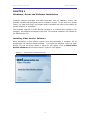
Installing Video Monitor Software
When purchasing a Video Monitor system from Med Associates, a computer will be
shipped with the software already installed. To re-install the software, insert the Video
Monitor CD, and the screen shown in Figure 4-1 will appear. Click on Install Video
Monitor software and the screen shown in Figure 4-2 will appear.
Figure 4-1 - Video Monitor Installation Screen
- 31 -
MED ASSOCIATES INC.
VIDEO MONITOR
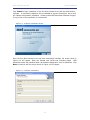
Click Install to begin installation of the Fire Wire Camera Driver and the Video Monitor
software. A successful installation will be indicated by a green check mark, and a red X
will indicate unsuccessful installation. Please contact MED Associates Customer Support
if any portion of the installation is unsuccessful.
Figure 4-2 - Customer Information Screen
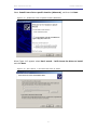
Once the Fire Wire Camera Driver has been successfully installed, the screen shown in
Figure 4-3 will appear. Enter the desired User Name and Company Name. MED
Associates issues the password when the Software Registration form is submitted. Click
Next to continue and the screen shown in Figure 4-4 will appear.
Figure 4-3 – Customer Information
- 32 -
MED ASSOCIATES INC.
VIDEO MONITOR
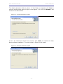
The default destination folder is shown. If this folder is acceptable, click Next to
continue and the screen shown in Figure 4-5 will appear. If it is not, click Browse… and
browse to the desired folder.
Figure 4-4 – Choose Destination Location
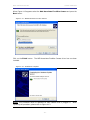
If all of the information entered was corrected, click Install to complete the Video
Monitor software installation. The screen shown in Figure 4-6 will appear.
Figure 4-5 – Ready to Install the Program
- 33 -
MED ASSOCIATES INC.
VIDEO MONITOR
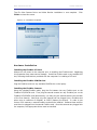
The Fire Wire Camera Driver and Video Monitor installation is now complete.
Finish to close this screen.
Click
Figure 4-6 – Installation Complete
Hardware Installation
Installing the FireWire PCI Card
Always turn off power to the computer prior to installing the FireWire card. Neglecting
this precaution may cause serious damage. Install the FireWire card in any available PCI
slot, following the directions provided with the computer for installing a PCI card.
Installing the FireWire PCMCIA Card
Plug the FireWire card into any available PCMCIA slot on the laptop.
Installing the FireWire Cameras
Using the included FireWire cable, plug the first camera into any FireWire port on the
FireWire PCI/PCMCIA card. Then plug the second camera into any FireWire port on the
FireWire PCI/PCMCIA card (alternatively, you may plug the second camera into the back
of the first camera). Note that only two cameras can be plugged into a FireWire card
when using a resolution of 640x480, at 30FPS (frames per second). In order to use
three or four cameras, a second FireWire card must be installed. Cameras three and four
must then be plugged into the second FireWire card. Once the cameras are plugged into
the computer, the appropriate driver must be installed.
- 34 -
MED ASSOCIATES INC.
VIDEO MONITOR
Installing the FireWire Camera Driver
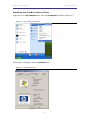
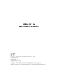
Right-click on the My Computer icon, then click Properties as shown in Figure 4-7.
Figure 4-7 – My Computer Properties
When Figure 4-8 appears, click the Hardware tab.
Figure 4-8 - System Properties
- 35 -
MED ASSOCIATES INC.
VIDEO MONITOR
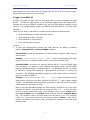
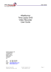
Now click on the Device Manager button, see Figure 4-9.
Figure 4-9 - Device Manager
Click on the Imaging Devices icon, and each camera that is plugged in should show up
as a “Generic 1394 Desktop Camera”. Select the first camera, and then go to Action |
Update Driver as shown in Figure 4-10.
Figure 4-10 - Imaging Devices
- 36 -
MED ASSOCIATES INC.
VIDEO MONITOR
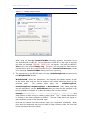
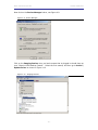
Select Install from a list or specific location (Advanced), and then click Next.
Figure 4-11 - Install from a list or specific location (Advanced)
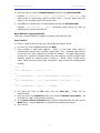
When Figure 4-12 appears select Don’t search. I will choose the driver to install
and click Next.
Figure 4-12 - Don't search. I will choose the driver to install.
- 37 -
MED ASSOCIATES INC.
VIDEO MONITOR
When Figure 4-13 appears select the Med Associates Fire Wire Camera and press the
Next button.
Figure 4-13 - MED Associates Fire Wire Camera
Click on the Finish button. The MED Associates FireWire Camera driver has now been
installed.
Figure 4-14 - Installation Complete
NOTE: This procedure must be repeated for each camera that is plugged in.
repeating the procedure, please refer to Figure 4-13.
- 38 -
When