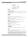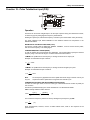
1
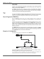
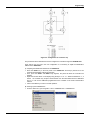
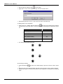
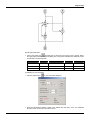
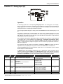
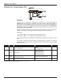
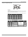
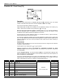
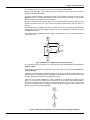
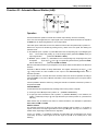
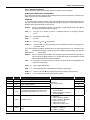
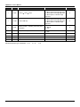
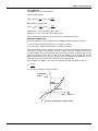
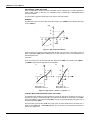
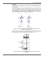
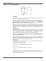
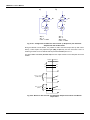
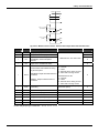
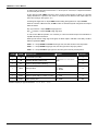
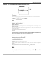
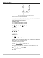
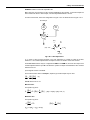
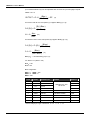
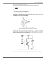
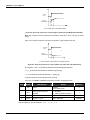
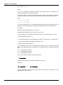
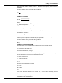
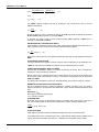
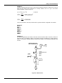
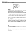
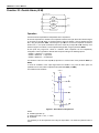
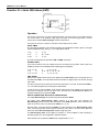
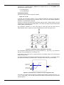
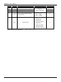
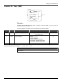
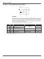
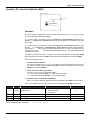
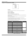
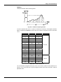
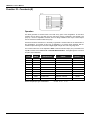
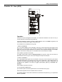
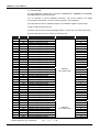
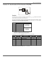
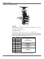
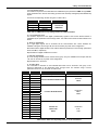
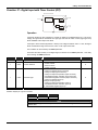
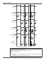
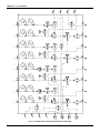
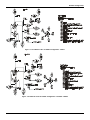
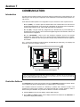
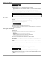
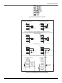
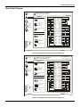
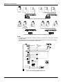
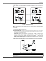
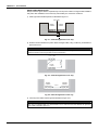
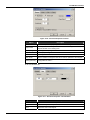
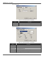
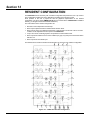
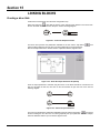
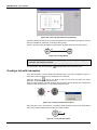
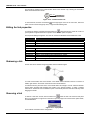
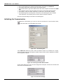
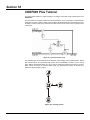
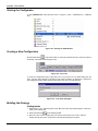
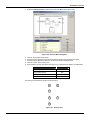
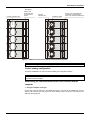
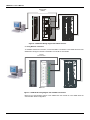
Library of Function Blocks
The controller can also be locked in Local or in Remote by the parameter CLKR.
After a power interruption, the controller will return to operation in the mode (Local or Remote)
selected by the parameter CTON.
The block features bumpless Local-Remote transfer, with adjustable changing rate (Slew Rate,
ASLW). This feature avoids abrupt changes in the Setpoint, and, consequently, in the process,
when the Setpoint is switched from Local to Remote.
Remote to Local transfer is balanced, that is, the Local register tracks the Remote Setpoint, when
operating in Remote mode. This can be used to implement Setpoint tracking when the loop is in
manual.
In a Setpoint tracking configuration the SP=PV in manual mode. The PV is manually adjusted to the
desired Setpoint by using the MV < > and < >. Then he can switch back to automatic mode and
the Setpoint will remain.
The LOG block inverts the MANUAL status signal to a AUTOMATIC, since Local Setpoint is desired
in automatic mode.
AI
001
2
B
D APID A
039 E
47
A
A/M 40
035
39
A
225 L/R
CLKR=1
031
131
A LOG CNOT=1
085 CLOG=0
A
CO
Fig 4.7.1 L/R Selector Configuration for Setpoint Tracking
The maximum and minimum limits for the Local Setpoint actuator are established in the parameters
ALOW and AUPP.
If it is necessary to have limits on the Remote Setpoint, this shall be done by means of Function 23 Limiter with Alarm.
In addition to the analog signal generated internally (in Local mode) or externally (in Remote Mode), the
block has two discrete outputs; the first is at high logic level when the block is in Remote mode and the
second is at high logic level when the operating mode is Local.
When one of the outputs 225/226/227 or 228 is visualized on the Alphanumeric Display and the
block is in Local mode, the register may be actuated by the Front Panel (Local Setpoint). Besides,
should this output signal be from inputs A or B (Remote Setpoint), and this input is linked to the
output of an adjustment block, this adjustment block will also be actuated by the Front Panel. This
feature is used in the following configuration.
ADD
099
233
A
L/R
031
255
A
FV
027
Fig 4.7.2 - L/R Selector Configuration for Internal or External Register Actuation
4.11