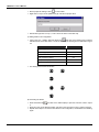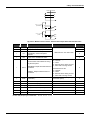
1
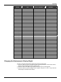
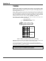
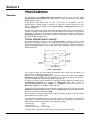
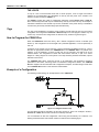
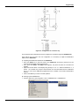
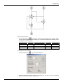
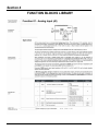
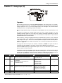
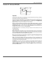
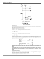
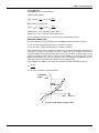
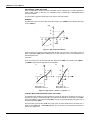
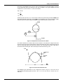
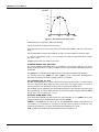
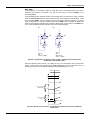
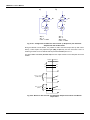
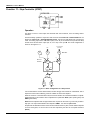
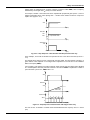
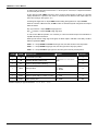
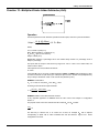
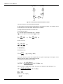
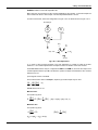
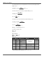
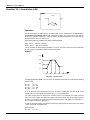
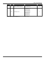
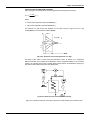
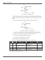
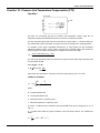
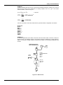
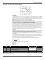
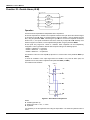
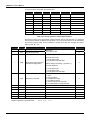
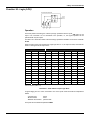
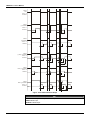
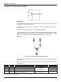
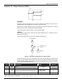
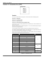
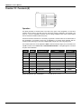
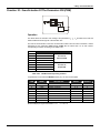
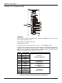
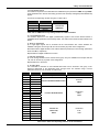
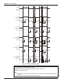
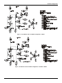
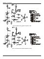
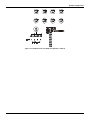
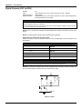
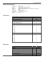
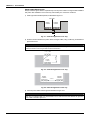
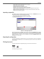
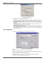
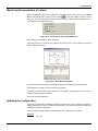
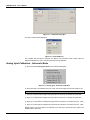
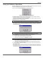
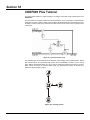
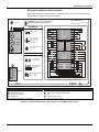
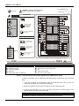
Library of Function Blocks
Function 01 - Analog Input (AI)
Operation
All the analog inputs have a corresponding Analog Input block. The analog input 2, for example,
which is connected to terminal 2, corresponds to block BLK002. The input to the circuit is always a
voltage signal (0-5 V or 1-5 V). If a current signal (0-20 mA or 4-20 mA) be used, a Shunt resistor
shall be placed in the corresponding terminal block position.
The input signal passes through an analog second order BESSEL filter with cutoff frequency at 15
Hz.
The result is converted into a digital number and in this form, it passes through a four point
calibration process in which 0V, 1V, 3V and 5V are made to correspond respectively to 0, 20, 60
and 100% for 0-20 mA/0-5 V input and -25, 0, 50 and 100% for 4-20 mA/1-5 V input. See the
CALIBRATION section for further details.
After conditioning, the signal is digitally filtered with an adjustable time constant. It can be linearized
in accordance with a curve established in the Function 31 - Linearization Curve (Blocks 109 to
116), configured in Loop G. This curve is selected by CLIN and may be used with 13 or 26 pairs of
points x, y, interconnected by straigh line segments. The curves that may be performed are show on
table 4.31.1 page 4.59.
The signal can also have square root extraction, selectable by CSQR. The square root has an
adjustable cutoff point (ACUT) for low signals. All values below ACUT will be considered 0%.
Parameter CSQR permits input signal selection (4-20 mA/1-5 V or 0-20 mA/0-5 V) and to decide
whether square root will be extracted.
In Burnout (signal after calibration smaller than -2% or greater than +102%), an Alarm can be
indicated on the front panel (if CFRT=1) and a Burnout alarm signal can be activated. This signal
can be used, for example, to switch the process variable to another input through a block of the
Function 29 - Input Selector or to force the controller's output to an emergency position.
TYPE
MNEM
DESCRIPTION
I
CFRT
"Burnout" indication on the front panel
I
CLIN
Linearization
(See Table 4.31.1 on Function 31 –
Linearization Curve)
I
CSQR
Signal Selection and Square Root extraction
P
ACUT
Cutoff level for square root extraction
0.00 - 100.00%
1.00%
P
ATIM
Filter time constant
0.00 - 30.00s
0.20s
Number of Bytes per Type of Parameter: A = 4
C=6
RANGE
0-No/1-Yes
2-Yes with Auto Ack
0-No
1?8/Curves 1?8
9-Curves 1 and 2
10-Curves 3 and 4
11-Curves 5 and 6
12-Curves 7 and 8
0-No (1 to 5V or 4 to 20mA)
1-Yes (1 to 5V or 4 to 20mA)
2-No (0 to 5V or 0 to 20mA)
3-Yes (0 to 5V or 0 to 20mA)
DEFAULT
0
0
0
L=0
4.3