1
LC-NMR
Accessory
Installation
Pub. No. 01-999036-00, Rev. C0800
LC-NMR Accessory
Installation
Pub. No. 01-999036-00, Rev. C0800
Revision history:
As 87-195280-00 –
A0496 – Initial release
B1096 – added Analyte Collector and other changes
B0397 – added J2 voltage selector and interface box jumper settings
C0997 – updated for VNMR 6.1, added sample info for delay calibration.
C1297 – added synch cable and 9065 detector.
As 01-999036-00 –
A0398 – changed part number from 87-195280-00 to 01-999036-00
B0299 – moved operation sections to User Guide: Liquids and updated manual.
B0599 – updates for Cascade, delay time calibration, and STAR software.
C0800 – Add ProStar pump and detector; update Cascade. General updates
Applicability of manual:
LC-NMR Accessory for UNITYINOVA, UNITYplus, and UNITY NMR spectrometer
systems
Technical contributors: Chris Kellogg, Karen Salomon, Ron Haner, Andy Myles,
Steve Smallcombe, Paul Keifer
Technical writer: Dan Steele, Mike Miller
Technical editor: Dan Steele
Copyright 2000 by Varian, Inc.
3120 Hansen Way, Palo Alto, California 94304
http://www.varianinc.com
All rights reserved. Printed in the United States.
The information in this document has been carefully checked and is believed to be
entirely reliable. However, no responsibility is assumed for inaccuracies. Statements in
this document are not intended to create any warranty, expressed or implied.
Specifications and performance characteristics of the software described in this manual
may be changed at any time without notice. Varian reserves the right to make changes in
any products herein to improve reliability, function, or design. Varian does not assume
any liability arising out of the application or use of any product or circuit described
herein; neither does it convey any license under its patent rights nor the rights of others.
Inclusion in this document does not imply that any particular feature is standard on the
instrument.
UNITY
INOVA, MERCURY, Gemini, GEMINI 2000, UNITYplus, UNITY, VXR, XL, VNMR,
VnmrS, VnmrX, VnmrI, VnmrV, VnmrSGI, MAGICAL II, AutoLock, AutoShim,
AutoPhase, limNET, ASM, and SMS are registered trademarks or trademarks of Varian,
Inc. Sun, Solaris, CDE, Suninstall, Ultra, SPARC, SPARCstation, SunCD, and NFS are
registered trademarks or trademarks of Sun Microsystems, Inc. and SPARC
International. Oxford is a registered trademark of Oxford Instruments LTD.
Ethernet is a registered trademark of Xerox Corporation. VxWORKS and VxWORKS
POWERED are registered trademarks of WindRiver Inc. Other product names in this
document are registered trademarks or trademarks of their respective holders.
Table of Contents
SAFETY PRECAUTIONS ................................................................................... 7
Chapter 1. Introduction .................................................................................. 11
1.1 About This Manual ....................................................................................................
1.2 Compatibility .............................................................................................................
1.3 Preinstallation Requirements .....................................................................................
Equipment, Samples, and Solvents ..................................................................
Site ...................................................................................................................
Personnel .........................................................................................................
1.4 Site Layout Guidelines ...............................................................................................
LC-NMR Minimum Room Layout .................................................................
LC-NMR Suggested Room Layout 1 ..............................................................
LC-NMR Suggested Room Layout 2 ..............................................................
1.5 Preparing Solvents .....................................................................................................
1.6 Caring for the HPLC System and Microflow Probe ..................................................
11
12
13
13
13
13
14
15
16
17
18
18
Chapter 2. HPLC Hardware Setup ................................................................. 19
2.1 Assembling the Valves and ProStar LC Pump Plumbing ..........................................
2.2 Setting Up the ProStar LC Detector ...........................................................................
Setting Up the ProStar 310 Detector ...............................................................
Setting Up the ProStar 330 Detector ...............................................................
2.3 Installing the Stop-Flow Valve and Plumbing ............................................................
Unpack and Connect Plumbing .......................................................................
Prepare the Transfer Tube ................................................................................
2.4 Unpacking and Assembling the LC STAR Workstation ............................................
2.5 Connecting the Stop-Flow Cable ...............................................................................
2.6 Installing the Powered Event Module ........................................................................
Connecting the Injector Valve and the Pump ..................................................
Connecting the Source Air ...............................................................................
2.7 Leak-Testing the System ............................................................................................
Running the Leak Test .....................................................................................
Interpreting Leak Test Results .........................................................................
2.8 Using the LC Pump ....................................................................................................
Creating an Initial Pump Method ....................................................................
Creating a Relay Program ...............................................................................
Priming the Pump ............................................................................................
Flushing the Probe Flow Cell ..........................................................................
Purging the Transfer Tube ...............................................................................
Transferring a Solvent into the Probe ..............................................................
19
21
21
22
25
25
26
27
28
31
31
32
34
34
35
36
36
37
38
39
40
40
Chapter 3. Software Installation: Cascade, Drivers, STAR 5.3 ................... 43
3.1 Loading the VEE Samples ......................................................................................... 43
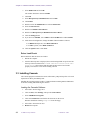
3.2 Installing Software Drivers ........................................................................................ 43
01-999036-00 C0800
LC-NMR Accessory Installation
3
Table of Contents
3.3
3.4
3.5
3.6
3.7
Driver Installation ............................................................................................
Driver Load Check ..........................................................................................
Installing Cascade ......................................................................................................
Resolving Sound Card Conflict on DELL Computers ...............................................
Reinstalling Cascade for Windows 95/98 ..................................................................
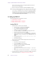
Setting Up STAR 5.31 ...............................................................................................
Loading STAR 5.31 .........................................................................................
Building a Method in STAR 5.31 ....................................................................
Setting Up the Ethernet Connection ..........................................................................
43
44
44
45
45
46
46
48
50
Chapter 4. LC-NMR Analyte Collector .......................................................... 51
4.1
4.2
4.3
4.4
Connecting the Analyte Collector to the LC Workstation .........................................
Installing the Analyte Collector Plumbing .................................................................
Analyte Collector Flow Diagrams .............................................................................
Setting Up Software for Analyte Collector ................................................................
51
53
54
56
Chapter 5. LC System Calibrations .............................................................. 57
5.1 Calibrating LC1D WET .............................................................................................
5.2 13C Sideband Suppression .........................................................................................
5.3 Calibrating the Delay Time ........................................................................................
Calibrating from the LC Detector to the Microflow Probe .............................
Calibrating from the LC Detector to the Analyte Collector ............................
Calibrating from the Analyte Collector to the Microflow Probe .....................
5.4 New Solvent Concentration .......................................................................................
57
58
58
58
60
60
61
Index ................................................................................................................. 63
4
LC-NMR Accessory Installation
01-999036-00 C0800
List of Figures
Figure 1. LC-NMR Block Diagram................................................................................................
Figure 2. Mounting the Injector and Purge/Prime Valves...............................................................
Figure 3. 310 Detector Voltage and Device Address Switches.......................................................
Figure 4. ProStar 330 Transport Screw Locations..........................................................................
Figure 5. ProStar 330 Flow Cell Support Removal ........................................................................
Figure 6. ProStar 330 Sponge Removal..........................................................................................
Figure 7. ProStar 330 Analog Output Board Install .......................................................................
Figure 8. Stop-Flow Valve Plumbing Connection Diagram ...........................................................
Figure 9. Diagram for Connecting the Stop-Flow Cable with 310 Detector..................................
Figure 10. Diagram for Connecting the Stop-Flow Cable with 330 Detector................................
Figure 11. Interface Box Jumper Settings ......................................................................................
Figure 12. UNITYINOVA Breakout Panel Connectors........................................................................
Figure 13. UNITYplus Pulse Sequence Controller Board, Front Panel .........................................
Figure 14. Powered Event Module, Back Panel Connectors ..........................................................
Figure 15. Injector Valve, Top View ...............................................................................................
Figure 16. Connecting the Regulator to the Cross Connector ........................................................
Figure 17. Status Display for Method 1..........................................................................................
Figure 18. Method Actions Display................................................................................................
Figure 19. Method 1 Conditions Display .......................................................................................
Figure 20. Relay Program Display .................................................................................................
Figure 21. Prime Valve and Drain on Front of LC Pump ...............................................................
Figure 22. STAR Configuration Window .......................................................................................
Figure 23. STAR System Control Window.....................................................................................
Figure 24. STAR Pump Method Window.......................................................................................
Figure 25. Detector Method Windows............................................................................................
Figure 26. LC-NMR Analyte Collector ..........................................................................................
Figure 27. Analyte Collector Hydraulic Connections.....................................................................
Figure 28. Flow Diagram for Collecting Separated Peaks .............................................................
Figure 29. Flow Diagram for On-Flow...........................................................................................
Figure 30. Flow Diagram for Stop-Flow—Stopped .......................................................................
Figure 31. Flow Diagram for Loop Elution....................................................................................
Figure 32. System Configuration Window .....................................................................................
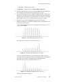
Figure 33. Profile Showing Delay Time is Correct.........................................................................
Figure 34. Profile Showing the Delay Time is Too Short ...............................................................
Figure 35. Profile Showing the Delay Time is Too Long ...............................................................
01-999036-00 C0800
LC-NMR Accessory Installation
12
20
21
22
22
23
23
26
28
29
30
30
31
32
32
33
36
36
37
37
39
47
47
48
49
52
53
54
54
55
55
56
59
59
59
5
List of Tables
Table 1. Pump Method 1 Conditions ............................................................................................. 37
Table 2. Initial Relay Program for Pump Method 1 ...................................................................... 38
Table 3. Analyte Collector Wire Connections ............................................................................... 52
6
LC-NMR Accessory Installation
01-999036-00 C0800
SAFETY PRECAUTIONS
SAFETY PRECAUTIONS
The following warning and caution notices illustrate the style used in Varian manuals for
safety precaution notices and explain when each type is used:
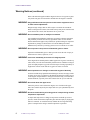
WARNING: Warnings are used when failure to observe instructions or precautions
could result in injury or death to humans or animals, or significant
property damage.
CAUTION:
Cautions are used when failure to observe instructions could result in
serious damage to equipment or loss of data.
Warning Notices
Observe the following precautions during installation, operation, maintenance, and repair
of the instrument. Failure to comply with these warnings, or with specific warnings
elsewhere in Varian manuals, violates safety standards of design, manufacturing, and
intended use of the instrument. Varian assumes no liability for customer failure to comply
with these precautions.
WARNING: Persons with implanted or attached medical devices such as
pacemakers and prosthetic parts must remain outside the 5-gauss
perimeter from the centerline of the magnet.
The superconducting magnet system generates strong magnetic fields that can
affect operation of some cardiac pacemakers or harm implanted or attached
devices such as prosthetic parts and metal blood vessel clips and clamps.
Pacemaker wearers should consult the user manual provided by the pacemaker
manufacturer or contact the pacemaker manufacturer to determine the effect on
a specific pacemaker. Pacemaker wearers should also always notify their
physician and discuss the health risks of being in proximity to magnetic fields.
Wearers of metal prosthetics and implants should contact their physician to
determine if a danger exists.
Refer to the manuals supplied with the magnet for the size of a typical 5-gauss
stray field. This gauss level should be checked after the magnet is installed.
WARNING: Keep metal objects outside the 10-gauss perimeter from the centerline
of the magnet.
The strong magnetic field surrounding the magnet attracts objects containing
steel, iron, or other ferromagnetic materials, which includes most ordinary
tools, electronic equipment, compressed gas cylinders, steel chairs, and steel
carts. Unless restrained, such objects can suddenly fly towards the magnet,
causing possible personal injury and extensive damage to the probe, dewar, and
superconducting solenoid. The greater the mass of the object, the more the
magnet attracts the object.
Only nonferromagnetic materials—plastics, aluminum, wood, nonmagnetic
stainless steel, etc.—should be used in the area around the magnet. If an object
is stuck to the magnet surface and cannot easily be removed by hand, contact
Varian service for assistance.
01-999036-00 C0800
LC-NMR Accessory Installation
7
SAFETY PRECAUTIONS
Warning Notices (continued)
Refer to the manuals supplied with the magnet for the size of a typical 10-gauss
stray field. This gauss level should be checked after the magnet is installed.
WARNING: Only qualified maintenance personnel shall remove equipment covers
or make internal adjustments.
Dangerous high voltages that can kill or injure exist inside the instrument.
Before working inside a cabinet, turn off the main system power switch located
on the back of the console, then disconnect the ac power cord.
WARNING: Do not substitute parts or modify the instrument.
Any unauthorized modification could injure personnel or damage equipment
and potentially terminate the warranty agreements and/or service contract.
Written authorization approved by a Varian, Inc. product manager is required to
implement any changes to the hardware of a Varian NMR spectrometer.
Maintain safety features by referring system service to a Varian service office.
WARNING: Do not operate in the presence of flammable gases or fumes.
Operation with flammable gases or fumes present creates the risk of injury or
death from toxic fumes, explosion, or fire.
WARNING: Leave area immediately in the event of a magnet quench.
If the magnet dewar should quench (sudden appearance of gasses from the top
of the dewar), leave the area immediately. Sudden release of helium or nitrogen
gases can rapidly displace oxygen in an enclosed space creating a possibility of
asphyxiation. Do not return until the oxygen level returns to normal.
WARNING: Avoid liquid helium or nitrogen contact with any part of the body.
In contact with the body, liquid helium and nitrogen can cause an injury similar
to a burn. Never place your head over the helium and nitrogen exit tubes on top
of the magnet. If liquid helium or nitrogen contacts the body, seek immediate
medical attention, especially if the skin is blistered or the eyes are affected.
WARNING: Do not look down the upper barrel.
Unless the probe is removed from the magnet, never look down the upper
barrel. You could be injured by the sample tube as it ejects pneumatically from
the probe.
WARNING: Do not exceed the boiling or freezing point of a sample during variable
temperature experiments.
A sample tube subjected to a change in temperature can build up excessive
pressure, which can break the sample tube glass and cause injury by flying glass
and toxic materials. To avoid this hazard, establish the freezing and boiling
point of a sample before doing a variable temperature experiment.
8
LC-NMR Accessory Installation
01-999036-00 C0800
SAFETY PRECAUTIONS
Warning Notices (continued)
WARNING: Support the magnet and prevent it from tipping over.
The magnet dewar has a high center of gravity and could tip over in an
earthquake or after being struck by a large object, injuring personnel and
causing sudden, dangerous release of nitrogen and helium gasses from the
dewar. Therefore, the magnet must be supported by at least one of two methods:
with ropes suspended from the ceiling or with the antivibration legs bolted to
the floor. Refer to the Installation Planning Manual for details.
WARNING: Do not remove the relief valves on the vent tubes.
The relief valves prevent air from entering the nitrogen and helium vent tubes.
Air that enters the magnet contains moisture that can freeze, causing blockage
of the vent tubes and possibly extensive damage to the magnet. It could also
cause a sudden dangerous release of nitrogen and helium gases from the dewar.
Except when transferring nitrogen or helium, be certain that the relief valves are
secured on the vent tubes.
WARNING: On magnets with removable quench tubes, keep the tubes in place
except during helium servicing.
On Varian 200- and 300-MHz 54-mm magnets only, the dewar includes
removable helium vent tubes. If the magnet dewar should quench (sudden
appearance of gases from the top of the dewar) and the vent tubes are not in
place, the helium gas would be partially vented sideways, possibly injuring the
skin and eyes of personnel beside the magnet. During helium servicing, when
the tubes must be removed, carefully follow the instructions and safety
precautions given in the manual supplied with the magnet.
Caution Notices
Observe the following precautions during installation, operation, maintenance, and repair
of the instrument. Failure to comply with these cautions, or with specific cautions elsewhere
in Varian manuals, violates safety standards of design, manufacturing, and intended use of
the instrument. Varian assumes no liability for customer failure to comply with these
precautions.
CAUTION:
Keep magnetic media, ATM and credit cards, and watches outside the
5-gauss perimeter from the centerline of the magnet.
The strong magnetic field surrounding a superconducting magnet can erase
magnetic media such as floppy disks and tapes. The field can also damage the
strip of magnetic media found on credit cards, automatic teller machine (ATM)
cards, and similar plastic cards. Many wrist and pocket watches are also
susceptible to damage from intense magnetism.
Refer to the manuals supplied with the magnet for the size of a typical 5-gauss
stray field. This gauss level should be checked after the magnet is installed.
01-999036-00 C0800
LC-NMR Accessory Installation
9
SAFETY PRECAUTIONS
Caution Notices (continued)
CAUTION:
Keep the PCs, (including the LC STAR workstation) beyond the 5gauss perimeter of the magnet.
Avoid equipment damage or data loss by keeping PCs (including the LC
workstation PC) well away from the magnet. Generally, keep the PC beyond the
5-gauss perimeter of the magnet. Refer to the Installation Planning Guide for
magnet field plots.
CAUTION:
Check helium and nitrogen gas flowmeters daily.
Record the readings to establish the operating level. The readings will vary
somewhat because of changes in barometric pressure from weather fronts. If
the readings for either gas should change abruptly, contact qualified
maintenance personnel. Failure to correct the cause of abnormal readings could
result in extensive equipment damage.
CAUTION:
Never operate solids high-power amplifiers with liquids probes.
On systems with solids high-power amplifiers, never operate the amplifiers
with a liquids probe. The high power available from these amplifiers will
destroy liquids probes. Use the appropriate high-power probe with the highpower amplifier.
CAUTION:
Take electrostatic discharge (ESD) precautions to avoid damage to
sensitive electronic components.
Wear a grounded antistatic wristband or equivalent before touching any parts
inside the doors and covers of the spectrometer system. Also, take ESD
precautions when working near the exposed cable connectors on the back of the
console.
Radio-Frequency Emission Regulations
The covers on the instrument form a barrier to radio-frequency (rf) energy. Removing any
of the covers or modifying the instrument may lead to increased susceptibility to rf
interference within the instrument and may increase the rf energy transmitted by the
instrument in violation of regulations covering rf emissions. It is the operator’s
responsibility to maintain the instrument in a condition that does not violate rf emission
requirements.
10
LC-NMR Accessory Installation
01-999036-00 C0800
Chapter 1.
Introduction
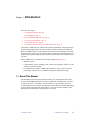
Sections in this chapter:
• 1.1 “About This Manual” this page
• 1.2 “Compatibility” page 12
• 1.3 “Preinstallation Requirements” page 13
• 1.4 “Site Layout Guidelines” page 14
• 1.5 “Preparing Solvents” page 18
• 1.6 “Caring for the HPLC System and Microflow Probe” page 18
The Varian LC-NMR accessory combines the separation capabilities of high-performance
liquid chromatography (HPLC) with the structure elucidation capabilities of NMR. The
HPLC and NMR systems are each complete and can be operated individually. LC-NMR
integrates the two systems into a new class of analytical instrument. Chromatography is an
analytical technique that, using the right conditions, separates individual components from
a mixture.
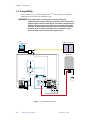
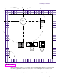
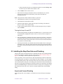
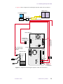
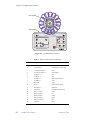
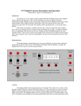
The LC-NMR accessory includes the following components (See Figure 1):
• Microflow probe.
• Complete HPLC system, including pump, variable-wavelength UV detector, PC, and
column, a peak sense module.
• LC-NMR software, added to VNMR, which includes a variety of pulse sequences,
pulse shapes, and macros for LC-NMR data acquisition and data processing.
1.1 About This Manual
The installation instructions in this manual primarily cover the integration of the HPLC
system with the NMR spectrometer. The major components—including the LC detector,
LC pump, and valves—of the HPLC system should be set up according to the Varian
Chromatography Systems manuals. The NMR spectrometer should be installed and running
properly before being integrated with the HPLC system. The first three chapters of this
manual provide instructions for integrating the two systems.
01-999036-00 C0800
LC-NMR Accessory Installation
11
Chapter 1. Introduction
1.2 Compatibility
The LC-NMR accessory is fully compatible with UNITYINOVA, UNITYplus, and UNITY
NMR spectrometer systems with a Microflow probe.
WARNING: Keep metal objects, including tools, electronic equipment,
compressed gas cylinders, steel chairs, and steel carts, away from the
magnet. Unless restrained, such objects can suddenly fly towards the
magnet, causing personal injury and extensive damage to the probe,
the dewar, and the superconducting solenoid. Only nonferromagnetic
materials (such as plastics, aluminum, wood, and stainless steel)
should be used in the area around the magnet dewar
LC
computer
NMR Console
LC
STAR
Magnet
4
5
Injector
Valve
2
6
1
3
Probe
Waste
Purge
valve
Waste
Pump
C
1
6
2
Stop-Flow
Valve
5
3
4
Mixer
Column
Detector
I O
I O
A
A
B
B
C
Figure 1. LC-NMR Block Diagram
12
LC-NMR Accessory Installation
01-999036-00 C0800
1.3 Preinstallation Requirements
1.3 Preinstallation Requirements
This section lists the items needed for the LC-NMR accessory installation. Everything
listed in this section must be in place before you begin the installation.
Equipment, Samples, and Solvents
You must have the following equipment, samples, and solvents:
• A nonmagnetic table, at least 0.9 m by 1.2 m (3 ft by 4 ft), to hold the LC hardware.
• Either gas cylinder of helium, outfitted with 0.25-inch OD Teflon tubing with aerator
(this will be used for sparging the acetonitrile solvent), or the necessary degassing
equipment. Do not use an aspirator.
• At least 300 mL of D2O, 99.8 atom percent or better.
• At least 100 mL of acetone-d6.
• At least 300 mL of OmniSolv brand acetonitrile (EM Science part no. AX0142-l).
• Research grade sucrose.
• At least three, 100-mL volumetric flasks for preparing standard samples.
• An appropriate waste container for HPLC effluent. The cover of the container must
have a hole in the top of about 2 mm diameter. The hole is used for the outlet of the
LC-NMR Microflow probe.
• Air supply for the pneumatic valve.
Site
Your site must have the following:
• Five, 110 Vac or 220 Vac outlets within 2m (6 ft) of where the table holding the LC
hardware will be located. Several extension cords should be available for the
installation.
• Approval by Varian of the proposed layout of the LC-NMR lab.
Personnel
A person experienced in liquid chromatography must be present during the installation.
Having this person on site ensures that vital information is shared regarding the following:
• The performance of the HPLC system.
• The interface between the LC system and the NMR spectrometer.
• The isolation of the LC system from the NMR spectrometer.
• The overall operation of the LC-NMR accessory.
At least one NMR spectroscopist must be present during the installation, calibration, and
system tests.
01-999036-00 C0800
LC-NMR Accessory Installation
13
Chapter 1. Introduction
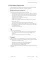
1.4 Site Layout Guidelines
This section provides guidelines for arranging an LC-NMR lab. The illustrations in this section provide a
room layout diagrams for you to use as a guideline for setting up your LC-NMR room.
The following room layouts are illustrated:
• “LC-NMR Minimum Room Layout” on page 15
• “LC-NMR Suggested Room Layout 1” on page 16
• “LC-NMR Suggested Room Layout 2” on page 17
Consider the following when developing a room layout:
• Stray magnetic fringe fields. The Installation Planning Guide that came with your system contains
magnetic field plots.
• The distance between the NMR console and the magnet must be less than 3 m (10 ft) to accommodate
cable lengths between the console and the preamplifier housing (magnet leg).
• The transfer tube between the LC system and the probe is 4.6 m (15 ft), no longer. Therefore, the distance
between the LC hardware and the magnet should be about 3 m (10 ft) to accommodate drops and rises.
• The room must provide access for cryogen servicing of the magnet. For cryogen servicing, cryogen
dewars need to be moved into the room, near the magnet.
• The LC STAR workstation (PC) should be set up close to the Sun host computers.
• Cable lengths from the LC STAR workstation (PC)—up to 3.35 m (11 ft) between the LC workstation
and the LC hardware; up to 12.2 m (40 ft) between the LC workstation and the NMR console.
• Cable lengths from the Sun workstation and the NMR console—up to 24.4 m (80 ft).
14
LC-NMR Accessory Installation
01-999036-00 C0800
1.4 Site Layout Guidelines
LC-NMR Minimum Room Layout
NMR
Console
Magnet
LC hardware
table
Sun host computer
{
LC STAR workstation
0.25 inch = 1 foot
Room dimensions are about 6.1 m × 6.1 m (20 ft × 20 ft). The standard NMR cabinet is 111 cm × 78 cm (44
in. × 31 in.). Typical table size is 183 cm × 76 cm (72 in. × 30 in.). The magnet is 97.8 cm (38.5 in.) in
diameter.
Refer to the Installation Planning Guide for component dimensions. Drawn approximately to scale.
01-999036-00 C0800
LC-NMR Accessory Installation
15
Chapter 1. Introduction
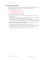
LC-NMR Suggested Room Layout 1
NMR
Console
Magnet
LC
hardware
table
LC STAR workstation
{
Sun host computer
0.25 inch = 1 foot
Room dimensions are about 6.7 m × 7.3 m (22 ft × 24 ft). The standard NMR cabinet is 111 cm × 78 cm (44
in. × 31 in.). Typical table size is 183 cm × 76 cm (72 in. × 30 in.). The magnet is 97.8 cm (38.5 in.) in
diameter.
Refer to the Installation Planning Guide for component dimensions. Drawn approximately to scale.
16
LC-NMR Accessory Installation
01-999036-00 C0800
1.4 Site Layout Guidelines
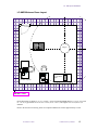
LC-NMR Suggested Room Layout 2
Magnet
LC
hardware
table
Sun host computer
LC STAR workstation
{
NMR
Console
0.25 inch = 1 foot
Room dimensions are about 7.3 m × 7.3 m (24 ft × 24 ft). The standard NMR cabinet is 111 cm × 78 cm (44
in. × 31 in.). Typical table size is 183 cm × 76 cm (72 in. × 30 in.). The magnet is 97.8 cm (38.5 in.) in
diameter.
Refer to the Installation Planning Guide for component dimensions. Drawn approximately to scale.
01-999036-00 C0800
LC-NMR Accessory Installation
17
Chapter 1. Introduction
1.5 Preparing Solvents
This section provides information to consider when preparing solvents for LC-NMR.
• De-gas or sparge solvents to prevent bubble formation in the probe cell.
• Filter solvents that have been prepared by mixing and/or dissolving one compound into
another to remove residual or precipitated solid material.
• Cover solvent containers for the following reasons:
• To prevent dust from accumulating
• To prevent excessive exposure to vapors
• To prevent pickup or exchange of D with H.
• Install a vent when the solvent container is connected to the HPLC system. This is
especially important for solvents that are being continuously sparged.
1.6 Caring for the HPLC System and Microflow Probe
This section provides recommendations about caring for the HPLC system and the
Microflow probe.
• Do not use solvents that are incompatible with PEEK, quartz, 316 stainless steel, tefzel,
or teflon. Also, do not use solvents or buffers that are incompatible with the column’s
packing. For example, high pH buffer systems may dissolve silica in C-18 and C-8
columns.
• Do not allow solvent to drip onto the top of the LC pump, the LC detector, or any other
electronic device where the solvent can penetrate the cabinet and reach the circuitry.
• If you are using buffers, flush the system with D2O or water daily to dissolve any salts
that might have precipitated.
• Do not leave buffers or only water in the HPLC system or Microflow probe. Bacteria
can grow and block tubing and the column. Always rinse the HPLC system and the
Microflow probe with D2O or water first, followed by a mixture of at least 25% organic
solvent and D2O or water.
• To prevent the probe from drying out between use, make sure that the probe inlet and
outlet ports are sealed with a piece of tubing connected between them or with no-hole
ferrules connected to each port. Similarly, seal the 310 detector if it will not be used
for a while.
• Periodically flush the probe with the strong solvent you are using to remove any
compounds that may adhere to the probe flow cell.
• Do not connect tubing with less than a 0.010-inch internal diameter (I.D.) to the probe
outlet (larger I.D.s are preferred). Long runs of small I.D. tubing cause excessive
pressure in the probe that can break seals and create leaks within the probe.
• Do not subject the probe to excessive mechanical vibrations or violent motion.
18
LC-NMR Accessory Installation
01-999036-00 C0800
Chapter 2.
HPLC Hardware Setup
Sections in this chapter:
•
•
•
•
•
•
•
•
2.1 “Assembling the Valves and ProStar LC Pump Plumbing” this page
2.2 “Setting Up the ProStar LC Detector” page 21
2.3 “Installing the Stop-Flow Valve and Plumbing” page 25
2.4 “Unpacking and Assembling the LC STAR Workstation” page 27
2.5 “Connecting the Stop-Flow Cable” page 28
2.6 “Installing the Powered Event Module” page 31
2.7 “Leak-Testing the System” page 34
2.8 “Using the LC Pump” page 36
Most of the HPLC hardware is set up using the instructions provided in Varian
Chromatography Systems documentation. Detailed instructions are provided in this chapter
for plumbing the pump and valves, connecting the detector, assembling the LC STAR
workstation, and connecting the HPLC system to the NMR spectrometer. The NMR
spectrometer must be installed and running properly before the HPLC system can be
integrated with it. This chapter also provides some basic instructions for using the LC pump
and detector.
If you are unfamiliar with chromatographs, and with Varian STAR Chromatography
systems in particular, you may wish to read the Varian Chromatography Systems manuals
before beginning the HPLC hardware setup.
The installation kit provides two rolls of PEEK tubing. The blue PEEK tubing (0.010-inch
I.D.) is used to connect the various LC valves. The red PEEK tubing (0.005-inch I.D.) is
used as the transfer line, to connect the probe to the LC system.
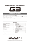
2.1 Assembling the Valves and ProStar LC Pump Plumbing
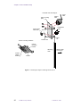
The injector valve, purge valve, column, valve mounting plate, mounting track, column
mounting hardware, and thumbscrews are packaged in separate plastic bags in the universal
valve mounting kit. This kit enables you to mount these valves and the column onto the side
of the LC pump, which has holes tapped in both sides.
We suggest you mount the assembly on the left side of the pump to facilitate plumbing
connections. Figure 2 illustrates how the universal valve mounting kit is assembled.
Instructions in the Chromatography Systems manuals provide further information.
01-999036-00 C0800
LC-NMR Accessory Installation
19
Chapter 2. HPLC Hardware Setup
Universal valve mounting kit
Injector
valve
Valve mounting
plate
Control knob/
valve shaft
Inject
stem
purge/prime
valve
Jam nut
Weld
nut
Thumbscrew
Column mounting hardware
Column
mounting
bracket
Mounting
track
Column
retainer
bracket
Attach to side
of LC pump
Column
Figure 2. Mounting the Injector and Purge/Prime Valves
20
LC-NMR Accessory Installation
01-999036-00 C0800
2.2 Setting Up the ProStar LC Detector
2.2 Setting Up the ProStar LC Detector
Use the instructions provided in the Varian Chromatography Systems manuals to unpack
and set up the ProStar LC detector. Choose one of the procedures below to set up the
ProStar 310 detector or the ProStar 330 detector.
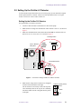
Setting Up the ProStar 310 Detector
Set up the ProStar 310 detector as follows:
1.
Connect a cable from J201 on the detector to J201 on the pump.
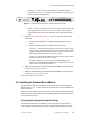
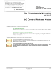
2.
Make sure the J2 voltage switch on the back of the detector is set to 1 V, as shown in
Figure 3.
3.
Make sure the thumbwheel switch (S201 DEVICE ADDR) on the back of the LC
detector is set to 3; if not, set it to 3, as shown in Figure 3.
J2 voltage switch
310 LC Detector
back panel
POWER
1V
10V
1mV
10mV
DATA
SYSTEM
OUTPUT
J1
CHART
RECORDER
OUTPUT
J2
PEAK
SENSE
RELAY
F1
2.5A SB
ATTENTION
1V
DATA
SYSTEM
OUTPUT
10V
J2
DIAGNOSTICS
PORT
RS232
J200
J3
J4
RELAY 1
J5
RELAY 2
J6
RELAY 3
J7
RELAY 4
J8
WIRED FOR
120 VAC
OPERATION
J9
READY OUT
ENABLE OUT
START IN
FAULT IN
SYNC SIGNALS
READY IN
ENABLE IN
START OUT
FAULT OUT
GPIB
IEEE 488
3
DEVICE
ADDR
J210
J10
Thumbwheel switch
S201
GPIB
IEEE 488
3
S201
DEVICE
ADDR
Figure 3. 310 Detector Voltage and Device Address Switches
4.
Make sure the wiring on the J2 connector is configured
as shown in the illustration on the right.
The J2 connector is incorrectly wired if the stop-flow
valve constantly rotates or the 16-port valve randomly
increments. Make sure the wiring matches the picture
to the right.
01-999036-00 C0800
J2 Rear (correctly wired)
Black
Screen
Red
LC-NMR Accessory Installation
21
Chapter 2. HPLC Hardware Setup
Setting Up the ProStar 330 Detector
Set up the ProStar 330 detector using the following procedures:
•
•
•
•
Unpacking the Detector and Removing Shipping Supports
Installing the Analog Output Board
Installing the High-Pressure Flow Cell
Loading the Control Software and Installing the ProStar 330 GPIB Card in the Dell
Computer
• Loading Polyview Software
• Turning the Lamp On and Off
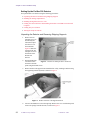
Unpacking the Detector and Removing Shipping Supports
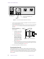
1.
Remove the two
transport screws, as
described by the
instructions taped
onto the cover of
the instrument.
Figure 4 shows the
location of the two
transport screws on
the bottom of the
ProStar 330
detector.
2.
Position the ProStar
Figure 4. ProStar 330 Transport Screw Locations
330 on the bench
and remove the side
panel using the thumb screws.
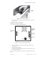
3.
Remove the flow cell support from around the flow cell by reaching in and removing
the supporting material by hand, as shown in Figure 5.
Figure 5. ProStar 330 Flow Cell Support Removal
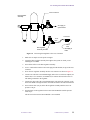
4.
22
Unscrew the thumbscrews from the Hg lamp. Remove the cover with the lamp and
remove the sponge from the detector, as shown in Figure 6.
LC-NMR Accessory Installation
01-999036-00 C0800
2.2 Setting Up the ProStar LC Detector
Figure 6. ProStar 330 Sponge Removal
5.
If the modules are to be stacked, the ProStar 330 should be placed on top of the
ProStar 230 plump.
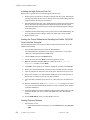
Installing the Analog Output Board
Figure 7 shows the location of the Analog Output board.
Analog Output
board
RELAY BOX
Connect to
pump start
out or relay
output
RECORDER RANGE
1
X
X
10
D-LINE
X 100
Connect to
GPIB on PC
RECORDER RANGE
NORMAL
LOW
PROCESSOR
GPIB
FUSE T3, 15AL/250V
ADDRESS
Set address
to 9
Figure 7. ProStar 330 Analog Output Board Install
1.
Remove the blank panel from the left side on the back of the ProStar 330 by
loosening the screws.
2.
Install the Analog Output board.
3.
Set the switch to normal for calibration purposes. The switch can be set to low for
better detection of small peaks.
The x1, x10, and x100 settings are only used with the recorder output, which will not be
accessed.
01-999036-00 C0800
LC-NMR Accessory Installation
23
Chapter 2. HPLC Hardware Setup
Installing the High-Pressure Flow Cell
Replace the low-pressure flow cell with the high-pressure flow cell.
1.
Remove the low-pressure flow cell that was shipped with the system. Pull back the
retaining ring and lift the flow cell out. Gently remove the attached tubing from the
supports and pull the unit away from the box.
2.
Install the high-pressure flow cell by pulling back the retaining ring and positioning
the new flow cell in the light path. Put the attached tubing into the side support.
Thread the inlet tubing out the inlet port and the outlet tubing through the outlet port
on the front panel.
3.
Attach the inlet and outlet tubing to the rest of the system with the PEEK fittings. Do
not overtighten because the tubing is made from Teflon and is easily crushed.
4.
Replace the side cover.
Loading the Control Software and Installing the ProStar 330 GPIB
Card in the Dell Computer
The National Instruments control software must be loaded onto the Dell PC before the
GPIB board is installed.
1.
Insert the National Instruments CD into the CD-ROM drive.
The standard Windows installation screen appears, followed by a screen called
“Welcome to National Instruments GPIB Setup.”
2.
Choose Other and click on the Next button.
3.
Accept the license and click Next on the line registrations screen.
4.
Start the installation and select all of the components in the Select the
Components window. Click on Next.
5.
Click Next on the Install screen. After the installation is finished, click Finish.
6.
Remove the National Instruments CD from the drive and shut down the computer.
7.
After the computer has shut down, turn off the power and remove the power cord.
8.
Remove the computer cover and install the GPIB board in one of the PCI slots, as
shown in the National Instrument Getting Started manual.
9.
After the board is installed, replace the covers, connect the power, and turn the PC
on.
10. Windows should briefly display a New Hardware Found dialog box. If it does
not, refer to the National Instruments manual for a way to manually force windows
to find the GPIB board.
11. Attach the GPIB cable to the PCI GPIB board and then to the GPIB connector on the
back of the ProStar 330. Do not connect this GPIB cable to any other ProStar
module.
12. Set the GPIB address on the rear of the ProStar 330 to 9.
Loading Polyview Software
1.
Insert the Star 5.3 CD.
• If the STAR installation wizard pops, up select Install and the select Polyview
2000.
24
LC-NMR Accessory Installation
01-999036-00 C0800
2.3 Installing the Stop-Flow Valve and Plumbing
• If the wizard does not pop up, use Windows Explorer to find the setup.exe
file in the Polyview folders on the STAR 5.3 CD.
2.
Click on Next on the welcome screen.
3.
Enter name and company information in the user information screen. For the
password, use the password found on the yellow sheet in the Polyview
Communications kit.
Note: This password is different than the STAR 5.3 password.
4.
Click Next on the software license agreement window.
5.
Click Next on the information window.
6.
Another window appears, which offers the option of selecting a file folder for
Polyview 2000. Use the default setting.
7.
A final window appears after the software is loaded saying the setup is complete.
Click on Finish.
Turning the Lamp On and Off
1.
Before turning the lamp on right after an installation, the LC system must be set up
in the instrument configuration window of Star 5.3. Refer to the next chapter for
instructions.
2.
Once the instrument is configured, the lamp is turned on from Star 5.3 software by
clicking the lamp on button on the ProStar 330 panel in System Control in Star 5.3.
If the PC has recently restarted, the ProStar 330 software must be downloaded before
it is possible to turn on the lamp.
3.
The lamp on the ProStar 330 should be shut off from STAR software. Turning off
the ProStar 330 by using the switch on the front panel requires the downloading of
the software control code when the ProStar 330 is turned on again. This takes several
minutes.
2.3 Installing the Stop-Flow Valve and Plumbing
The procedure in this section describes how to install the stop-flow valve and the plumbing.
If you have an Analyte Collector with your system, skip to “HPLC Hardware Setup” on
page 19—the Analyte Collector replaces the stop-flow valve.
For this procedure, use the 0.010-inch I.D. (blue striped) tubing to make the connections.
Use the tubing cutter (provided) to cut the tubing to the desired lengths. A 12-foot length
of red PEEK tubing will be used as the transfer line between the #4 port on the Stop-Flow
valve and the IN port on the probe. This tubing can be shortened to reduce the delay time.
The 9012 LC pump ships with stainless steel tubing. You may use the stainless steel tubing
instead of the PEEK tubing for connections between the LC pump, mixer, and purge valve.
All connections between the 310 LC detector, column, and probe must use the PEEK
tubing.
Unpack and Connect Plumbing
Unpack the stop-flow valve and place it on the table or cart near the injector and purge
valve.
01-999036-00 C0800
LC-NMR Accessory Installation
25
Chapter 2. HPLC Hardware Setup
1.
Connect a tube from the bottom port on the front of the pump to the large-volume
mixer (Part No. 03-919622-01).
2.
Connect a tube from the other end of the mixer to the #2 port on the stop-flow valve.
3.
Connect a tube from the #5 port on the stop-flow valve to the top port on the front of
the detector.
4.
Connect a tube from the #3 port on the stop-flow valve to one of the high-pressure
ports on the purge valve. Use the SSI ferrules provided in the kit to connect the tube
to the high pressure port.
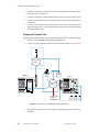
Prepare the Transfer Tube
Prepare the transfer tube, which is used to transfer solvents from the LC pump to the probe,.
1.
Find the 12-foot red PEEK tubing from the installation kit.
2.
Connect one end of the transfer tube to the #4 port on the stop-flow valve (Figure 8).
4
5
Injector
Valve
2
6
1
Waste
Purge
valve
Column
Detector
Pump
1
6
2
Stop-Flow
Valve
5
3
4
Mixer
3
C
I O
I O
A
Transfer tube
to probe
(Red PEEK)
A
B
B
C
Figure 8. Stop-Flow Valve Plumbing Connection Diagram
3.
26
For probe tests, this end of the transfer tube is temporarily connected to the pump
outlet port.
LC-NMR Accessory Installation
01-999036-00 C0800
2.4 Unpacking and Assembling the LC STAR Workstation
4.
If the Microflow probe is installed, connect the other end of the transfer tube to the
LC connector on the probe labeled IN. Otherwise, place this end in a waste container
near the magnet.
5.
Connect tube from the #1 and #6 ports on the
stop-flow valve to the waste container.
Valve Port
Connection
The stop-flow valve is now plumbed into the Varian
HPLC system. Go to the next section to set up the PC
workstation.
4
plug
3
from pump mixer
2
to purge valve
The table on the right gives an alternative plumbing
configuration that maintains pressure during stop-flow.
6
to NMR
1
from detector
5
to waste
2.4 Unpacking and Assembling the LC STAR Workstation
Use the instructions provided in the Varian Chromatography Systems manuals to unpack
and assemble the LC STAR workstation and to connect the GPIB (IEEE interface) cables
to the pump and detector. After the LC STAR workstation is assembled, use the following
procedures to install the ADC board in the PC, connect the PC cables, and install the LC
Stop Flow Monitor software.
CAUTION:
Avoid equipment damage or data loss by keeping the LC STAR
workstation PC well away from the magnet. Generally, keep the PC
beyond the 5-gauss perimeter of the magnet. Refer to the Installation
Planning Guide for magnet field plots.
This procedure describes how to install the ADC board into the LC STAR workstation. The
ADC board in the PC provides the basic analog and digital I/O interface between the LC
STAR workstation, LC hardware, and the NMR system.
1.
Make sure the PC power is off, but leave the power cord connected. Follow antistatic procedures because some of the parts in the PC and on the boards are static
sensitive.
2.
Remove the cover from the PC.
The PC contains a number of ISA-type expansion slots. One of the expansion slots
should already contain the GPIB IEEE interface board. The ADC board can be
installed in any one of the other free expansion slots.
3.
Choose the expansion slot for the ADC board. If the expansion slot has a slot cover
on the back panel of the PC, remove it.
4.
Locate the ADC board in the kit and carefully remove board from its packaging. Be
sure to hold the board only by its edges.
5.
Install the ADC board in the empty slot.
Carefully align the board connector with the connector inside the PC—the rear panel
connector on the board must face the rear of the PC. Then, using your thumbs, gently
push the board into the connector until the board is fully seated.
When correctly seated, the 50-pin ribbon cable connector on the ADC board should
be accessible through the back of the PC.
6.
Replace the cover on the PC.
The ADC board is now installed.
01-999036-00 C0800
LC-NMR Accessory Installation
27
Chapter 2. HPLC Hardware Setup
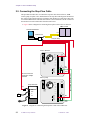
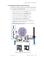
2.5 Connecting the Stop-Flow Cable
This procedure describes how to connect the stop-flow cable between the PC, NMR
console, pump, stop-flow valve, and the detector. The stop-flow cable begins at the interface
box at the 25-pin D-shell connector. The harness then divides into cables that connect the
LC with the NMR console and cables that connect to the LC hardware. The PC connects to
the interface box with a ribbon cable from the ADC board.
• Figure 9 shows a diagram for connecting the stop-flow cable to the 310 detector.
NMR console
LC STAR workstation
P3
interface box
P4
P8 (not used)
310 LC Detector
POWER
1V
10V
1mV
10mV
DATA
SYSTEM
OUTPUT
J1
CHART
RECORDER
OUTPUT
J2
PEAK
SENSE
RELAY
F1
2.5A SB
ATTENTION
DIAGNOSTICS
PORT
RS232
J200
P2
J3
J4
RELAY 1
J5
RELAY 2
J6
RELAY 3
J7
RELAY 4
J8
GPIB
IEEE 488
J9
S201
WIRED FOR
OPERATION
READY OUT
ENABLE OUT
START IN
FAULT IN
3
P9
310
DEVICE
ADDR
J201
J10
SYNC SIGNALS
P10
READY IN
ENABLE IN
START OUT
FAULT OUT
Do not connect P5
if using the analyte
collector.
Synch Cable (03-919941-00)
120 VAC
230 LC pump
POWER
PRESSURE
5 atm/mV
Stop-flow valve
MANUAL
SWITCHING
F1
3A SB
ATTENTION
RELAY 1
J3
RELAY 2
J4
RELAY 3
J5
RELAY 4
J6
RELAY 5
J7
RELAY 6
J8
WIRED FOR
120 VAC
OPERATION
2 AMP
3A9
J9
120V AC
50/60 HZ
DIAGNOSTICS
PORT
RS232
J200
P5
REMOTE
SWITCHING
J2
J1
READY OUT
ENABLE OUT
START IN
FAULT IN
SYNC SIGNALS
READY IN
ENABLE IN
START OUT
FAULT OUT
GPIB
IEEE 488
1
S201
DEVICE
ADDRESSES
P9
J201
J10
P10
310
Figure 9. Diagram for Connecting the Stop-Flow Cable with 310 Detector
28
LC-NMR Accessory Installation
01-999036-00 C0800
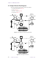
2.5 Connecting the Stop-Flow Cable
• Figure 10 shows a diagram for connecting the stop-flow cable to the 330 detector.
NMR console
LC STAR workstation
P3
interface box
P4
P8 (not used)
330 LC Detector
ProStar 330
Interface board
(01-906664-0x)
RELAY BOX
X
10
D-LINE
X 100
D-Line
RECORDER RANGE
NORMAL
LOW
PROCESSOR
GPIB
P2
FUSE T3, 15AL/250V
ADDRESS
Do not connect P5
if using the analyte
collector.
LC pump
Stop-flow valve
POWER
PRESSURE
5 atm/mV
MANUAL
SWITCHING
J2
J200
F1
3A SB
ATTENTION
RELAY 1
J3
RELAY 2
J4
RELAY 3
J5
RELAY 4
J6
RELAY 5
J7
RELAY 6
J8
WIRED FOR
120 VAC
OPERATION
2 AMP
3A9
J9
120V AC
50/60 HZ
DIAGNOSTICS
PORT
RS232
J1
P5
REMOTE
SWITCHING
Start out cable
03-935717-01
RECORDER RANGE
1
X
READY OUT
ENABLE OUT
START IN
FAULT IN
SYNC SIGNALS
READY IN
ENABLE IN
START OUT
FAULT OUT
GPIB
IEEE 488
1
S201
P9
DEVICE
ADDRESSES
J210
J10
P10
Y cable
01-906684-0x
Figure 10. Diagram for Connecting the Stop-Flow Cable with 330 Detector
01-999036-00 C0800
LC-NMR Accessory Installation
29
Chapter 2. HPLC Hardware Setup
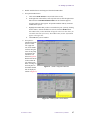
1.
Set the jumpers in the
interface box (see Figure 11)
for either UNITYINOVA/
UNITYplus or UNITY as
follows:
a.
Loosen the four
screws on the side of
the interface box.
b.
Remove the interface
box cover.
c.
Set jumpers J2 and J3
for UNITYINOVA/
UNITYplus or
UNITY:
UNITY
INOVA or
UNITYplus – set J2
and J3 to the side
nearest the U+/I
label.
UNITY – set J2 and
J3 to the side nearest
the UNITY label
d.
Set to
UNITY
Set to
INOVA or UNITYplus
Figure 11. Interface Box Jumper Settings
Replace the cover and tighten the four screws.
2.
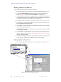
Connect the ribbon cable between the ADC board in the PC and the interface box.
3.
Connect the two cables to the NMR console as follows:
•
UNITY
INOVA—Connect one cable (P3) to SPARE 1 on the Breakout panel.
Connect the other cable (P4) to EXT TIME BASE on the DAC board. Figure 12
shows the connectors on the Breakout panel.
J8212
J8211
+5V
ATTEN
EMERG
J232 ACK —
J232 STB —
J233 ACK —
J233 STB —
R
S
J8216
SPARE 1
2
3
2
A
P
B
U
S
J8233
Figure 12.
30
LC-NMR Accessory Installation
U
S
E
R
J8215
RCVR GATE
J8201
UNITY
R
E
M
O
T
E
J8217
SPARE 2
S
T
A
T
U
S
J8219
SPARE 4
CLKSTB
ACK
A
P
J8218
SPARE 3
U
S
E
R
A
P
J8210
SPARE 5
J8213
INOVA Breakout Panel Connectors
01-999036-00 C0800
2.6 Installing the Powered Event Module
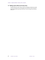
• UNITYplus—Connect one cable (P3) to SPARE 1 on the Pulse Sequence
Controller board (Figure 13). Connect the other cable (P4) to Ext Time Base on
the Pulse Sequence Controller board.
EXT TIME BASE
40 MHZ IN
J7
PULSE SEQUENCE
CONTROLLER
PF FULL
NT HDLP
LOOPING
RUNNING
J8
SPARE 1
J 12
J3 CABLE 993019
ACQ
F OVERUN
FIFO EMPTY APTO
SPARE 2
Figure 13. UNITYplus Pulse Sequence Controller Board, Front Panel
• UNITY—Connect one cable (P3) to SPARE 1 on the XL Interface board (in the
12-pin jumper pack J5, connect one wire to pin 7 and one wire to ground).
Connect the other cable (P4) to Ext Time Base on the Acquisition Controller
board.
4.
Refer to Figure 9 for the 310 or Figure 10 for the 330. Then make the following
connections:
a.
Connect the cable labeled P2 to J2 (DATA SYSTEM OUTPUT) on the
detector.
b.
Connect the following cables according to the type of detector:
310 detector – connect the cable labeled P9 to J9 on the LC pump. Connect
the Sync cable (03-919941-00) between J9 on the 310 detector and J10 on the
LC pump. Connect the end labeled P9 9010 to J9 on the 310 detector, and
connect the end labeled P10 310 to J10 on the LC pump.
330 detector – connect the cable labeled P10 to J10 on the LC pump. Connect
the cable labeled P9 to the J9 on the LC pump.
c.
If an analyte collector is not used, connect the cable labeled P5 to the
connector on the REMOTE SWITCHING cable of the stop-flow valve. If an
analyte collector is used, do not connect P5.
5.
Make sure the thumbwheel switch (S201 DEVICE ADDRESS) on the back of the
LC pump is set to 1; if not, set it to 1.
6.
Make sure the thumbwheel switch (S201 DEVICE ADDRESS) on the back of the
LC detector is set to 3; if not, set it to 3.
The stop-flow cable is now connected.
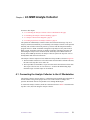
2.6 Installing the Powered Event Module
This procedure describes how to install the air line used by the Powered Event Module
(PEM), shown in Figure 14. This procedure also describes how to connect the PEM to the
other LC hardware.
The two procedures in this section describe how to connect the data cables and install the
air line into the source filter/regulator air line. The PEM requires a clean air/nitrogen source
of 60 psi minimum pressure.
Connecting the Injector Valve and the Pump
This procedure describes how to install the air lines to the injection valve and how to
connect the data cable between the Powered Event Module and the Detector. Leave the
power cord disconnected and the power switch off until all other connections are made.
01-999036-00 C0800
LC-NMR Accessory Installation
31
Chapter 2. HPLC Hardware Setup
POWER
off
J405
GAS
on
CB401
2A
wired for
120 VAC
IN
J406
200 VA Max
OUT
N.O. N.C.
J401
J402
Air in from
source (60 psi)
J403
green
J404
pink
J404 connects to RELAY 1 (J3)
on the pump
To injector
valve
Figure 14. Powered Event Module, Back Panel Connectors
1.
Connect a cable from J404 on the back of the PEM to the connector on the back of
the LC pump labeled RELAY 1 or J3.
2.
Connect one end of the long source air tube (1/8-inch O.D.) to the hose barb labeled
IN (see Figure 14). Leave the other end of this tube disconnected until the next
procedure.
3.
Make the air connections
between the PEM to the injector
valve as follows:
a.
Locate the two hose barbs
on the side of the injector
valve (see Figure 15).
b.
Connect one end of the
pink 1/8-inch O.D. tube to
the hose barb labeled N.C.
Connect the other end of
this tube to the hose barb
on the injector valve that is
farthest from the mounting
plate (see Figure 15).
c.
4.
Mounting
plate
Hose barbs
green
pink
Figure 15. Injector Valve, Top View
Connect one end of the green 1/8-inch O.D. tube to the hose barb labeled N.O.
Connect the other end of this tube to the hose barb on the injector valve that
is closest to the mounting plate (see Figure 15).
Go to the next procedure to connect the source air.
Connecting the Source Air
This procedure describes how to connect the regulator assembly (00-990668-00) to the
filter/regulator assembly used by the spectrometer. The new regulator is used to regulate the
air used by the Powered Event Module (PEM) and attaches to the cross connector as shown
in Figure 16. You will need a 1/4-inch Allen wrench. Wrap all threads with Teflon tape
before assembly.
32
LC-NMR Accessory Installation
01-999036-00 C0800
2.6 Installing the Powered Event Module
Cross connector
Filter/regulator
assembly
Air supply to
spectrometer
Connector
1/4-in.
tube
1/8-in.
tube
New regulator
assembly for PEM
Air supply to
PEM
Figure 16. Connecting the Regulator to the Cross Connector
1.
Make sure no sample is in the probe or magnet.
2.
Locate the filter/regulator assembly that supplies the system on which you are
installing the LC-NMR.
3.
Turn off the air flow to the filter/regulator assembly.
4.
Use a 1/4-inch Allen wrench to remove the plug from the bottom (or top) of the cross
connector.
5.
Screw the new regulator assembly into the cross connector as shown in Figure 16.
6.
Connect one end of the 1/8-inch PEM supply tube to the 1/8-inch hose adaptor (28849916-00). Use a connector (28-859986-00) to connect the hose barb to the 1/4inch tubing connected to the regulator.
7.
Connect the other end of the 1/8-inch PEM supply tube to the IN connector on the
back of the PEM. You might need the connectors 28-849916-00 and 28-859986-00.
8.
Turn on the air flow (60 psi) to the filter/regulator assembly until the source air
pressure is 60 psi.
9.
Turn the knob on the regulator for the Powered Event Module until the pressure
reads 60 psi.
The air line for the Powered Event Module is now installed.
01-999036-00 C0800
LC-NMR Accessory Installation
33
Chapter 2. HPLC Hardware Setup
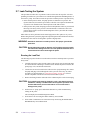
2.7 Leak-Testing the System
This procedure describes how to perform a leak test of the after the stop-flow valve and
plumbing is installed. A system leak test is available through the Extended Diagnostics of
the 9012 LC pump. Two leak test modes are provided: constant pressure or pressure decay.
• In the constant pressure mode, the pump operates to maintain a set pressure. The
reported leak rate (in microliters per minute) is the flow rate required to maintain the
set pressure. You should run the constant pressure mode leak test first.
• In the pressure decay mode, the pump pressurizes the hydraulics to the set pressure and
then stops. The decay of the pressure is then monitored as a function of time. The
pressure decay mode is useful for further diagnostics if the system fails the constant
pressure mode test.
Either leak test can be performed on the entire high-pressure flow path (not the probe).
When testing the entire system, the plug must be placed upstream from the detector because
most detector flow cells are not designed to operate at high pressure.
WARNING: Hazardous chemicals are under pressure. Use proper eye and skin
protection.
CAUTION:
Do not leak test the probe or detector cell. The high pressures used for
the leak test will damage the flow cells in the probe and detector. Never
exceed 2.0 mL/min flow rate through the probe.
Running the Leak Test
The following steps describe how to run the leak test in either constant pressure or pressure
decay mode.
1.
Carefully inspect the system for leaks (drips or salt crystals). Any obvious leaks must
be corrected before continuing. Locations to check include the piston seal drain, the
prime/purge valve, and all nuts and ferrules.
2.
Connect the solvent to be used for the leak test to the A proportioning valve. Prime
the pump and purge solvent through the entire system to remove any air (These
procedures are described later in “Using the LC Pump” on page 36). Choose a
solvent compatible with the last solvent used in the HPLC system.
3.
Remove the fitting from the outlet side of the column. Replace it with a known plug.
CAUTION:
4.
The hydraulic path must be plugged in such a way that the pressure
transducer is always included in the closed system. Operation of the
leak test without the pressure transducer in line could result in
damage to the pump.
On the 9012 LC pump, press and hold the SELECT key while simultaneously
turning on the power.
This will display the Extended Diagnostics Menu.
34
5.
Scroll to the Leak Test using the NEXT LINE key. Press START.
6.
Select either Constant Pressure or Pressure Decay mode using the INCREASE or
DECREASE key. Press NEXT LINE.
LC-NMR Accessory Installation
01-999036-00 C0800
2.7 Leak-Testing the System
7.
Set the pressure for the leak test. The pressure may be set from 10 to 410 atm. A good
test pressure would be slightly higher than the expected operating pressure.
Typically 200 atm is used. Press NEXT LINE.
8.
Close the prime valve if it is open. Press START.
After the pressure has stabilized, determine if a leak exists. If so, look for visible
signs of solvent leaking at one of the fittings.
Note: If a leak is found, do not tighten fittings while the system is pressurized and do not
overtighten the fitting. Instead do the following:
9.
a.
Press STOP to stop the leak test.
b.
Slowly release the pressure by carefully opening the prime valve.
c.
After the pressure has dropped to zero, tighten the fitting just enough to
correct the leak.
d.
Repeat the leak test.
When the leak test is finished, press STOP. Slowly release the pressure by carefully
opening the prime valve.
After the pressure has dropped to zero, remove the plug and reconnect the solvent
line. Turn off the power switch and then turn it back on to restore normal operation
of the 9012 LC pump.
Interpreting Leak Test Results
The constant pressure leak test displays the leak rate directly in µL/min. Because of the
extreme sensitivity of this test, take care in interpreting the reported leak rate. Relate the
leak rate to the operations flow rate to determine the significance of a reported value. For
example, a leak rate of less than 1 µL/min will be unimportant at a flow rate of 1mL/min.
The pressure decay mode displays a pressure drop and an elapsed time. If the hydraulics
being tested include the standard damper, the leak rate in µL/min may be estimated by
multiplying the pressure drop (in atm) by 1µL/atm and dividing by the elapsed time.
Both test modes are sensitive to fluctuations in ambient temperature, which can lead to
thermal expansion or contraction of the liquid in a closed system. This can cause small
fluctuations in the pressure or leak rate readings, but if a leak exists, it should become
apparent after the system has been under pressure for 5 or 10 minutes. As a rule of thumb,
a drop of water is approximately 50 µL. For organic solvents or mixtures of organic and
water, a drop is typically smaller than 50 µL. Therefore, with a leak rate exceeding 25 µL/
min, liquid should be visible at one of the fittings after several minutes of test. Lower leak
rates with a high percentage of organic solvent may not allow a visible amount of solvent
to accumulate because of evaporation. If no visible leak is seen, then the pump head may
be leaking internally (piston seal or inlet valve) or, if included in the test, the injector valve
might be leaking internally.
If the constant pressure leak test produces a higher leak rate than is tolerable after running
it for 10 minutes and no visible leaks can be found, run the pressure decay leak test. If the
results of this test are acceptable, then the fittings between the outlet check valve and the
plug are leak tight and an internal leak in the pump head is indicated. Check carefully
around the drain passage at the bottom of the pump head. If no leakage appears here, then
the inlet valve may be leaking, since leaks here can not be seen externally.
If the results of the tests are not conclusive, the leak tests should be repeated before
changing any of the hardware in the pump head.
01-999036-00 C0800
LC-NMR Accessory Installation
35
Chapter 2. HPLC Hardware Setup
2.8 Using the LC Pump
This section describes how to use the 9012 Solvent Delivery System (LC pump) from the
front panel keypad for the following operations:
•
•
•
•
•
•
Creating an Initial Pump Method
Creating a Relay Program
Priming the Pump
Flushing the Probe Flow Cell
Purging the Transfer Tube
Transferring a Solvent into the Probe
You will use these procedures when you are installing and testing the probe. All pump
operations described here are selected on the front panel of the pump. Refer to the Varian
Chromatography Systems manual for further details on using the pump.
To use the STAR Chromatography software for method building, see the LC-NMR
operation chapter in the manual User Guide: Liquids NMR.
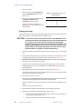
Creating an Initial Pump Method
This procedure describes how to create a method for testing the probe and calibrating the
system. The method created here uses parameters that are optimized for probe testing and
system calibration. You can create other, more intricate methods using the documentation
provided by Chromatography Systems or the LC-NMR operation chapter in the manual
User Guide: Liquids NMR.
A method is a group of parameters that control the pump. You use the front panel keypad
on the pump to create this method.
1.
If not already done, turn on the pump power as described in the Chromatography
Systems manual.
2.
Press the STATUS button in the OPERATION menu.
The display on the front of the pump shows a read-only status of current pump
conditions. Figure 17 shows the typical initial status display for method 1.
Meth
%A
%B
%C
Flow
Pres
Relays
Time
1
100
0
0
1,00
0
------
0.00
Figure 17. Status Display for Method 1
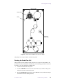
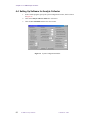
3.
Press the METHOD ACTIONS button in the TABLE SELECT menu. The display
shown in Figure 18 appears. The cursor should be under METHOD SELECT. If not,
use the cursor buttons to move the cursor.
Method
Error
Method
Metho
Run
Table
Select
Log
Copy
Delet
Log
Print
Figure 18. Method Actions Display
4.
36
With the cursor under METHOD SELECT, press SELECT.
LC-NMR Accessory Installation
01-999036-00 C0800
2.8 Using the LC Pump
The display shows Select Method – Press Select and allows you to choose
a method number. We will be setting up method 1, so press the INCREASE or
DECREASE button until 1 is displayed. Then press SELECT.
The display shows Method 1 Selected.
5.
Press SET CONDITIONS. The display shown in Figure 19 appears.
Method
Endtime
Action
Pmin/Pmax
Equil Time
1
6.00
Equil
0 / 300
0.00
Figure 19. Method 1 Conditions Display
6.
7.
Make the values the same as shown in
Table 1.
Table 1. Pump Method 1 Conditions
Use the CURSOR, INCREASE, and
DECREASE buttons to change the values.
Field
Value
Endtime
6.00
After the values are set to those shown in
Table 1, press STATUS to return to the
status display. Then go to the next
procedure to create a relay program.
Action
Equil
Pmin
0
Pmax
300
Equil Time
0.00
Creating a Relay Program
This procedure describes how to create the initial relay program for testing the probe and
calibrating the system. If you have other devices connected to your pump, such as an
autosampler or analyte collector, you might need to create a more detailed relay program,
as described in the Chromatography Systems manuals. For testing the probe and calibrating
the system, you only need to create a program for relay 1, which controls the injector valve.
Relays can be time programmed to control six external event relays. You will use the front
panel keypad on the pump to create this relay program.
1.
Press the RELAYS button in the TABLE SELECT menu.
The relay display for method 1 appears as shown in Table 20. The dashes (–) under
Relays On represent the six external event relays on the back of the pump.
Method
Line
Time
Relays On
1
1
0.00
------
Figure 20. Relay Program Display
2.
Press NEXT LINE in the EDIT menu. If the system says that no line exists, press
INSERT LINE to add a new line.
Line 2 is created. Notice that the time has changed from 0.00 to 0.01.
3.
Use the CURSOR buttons to move the cursor under the first dash under
Relays On. This represents relay 1, which is connected to the injector valve. Press
INCREASE to turn on relay 1.
4.
Press NEXT LINE in the EDIT menu. If the system says that no line exists, press
INSERT LINE to add a new line.
01-999036-00 C0800
LC-NMR Accessory Installation
37
Chapter 2. HPLC Hardware Setup
Line 3 is created.
5.
Move the cursor to the Time field and
push the INCREASE button until the
time is 1.00.
6.
Move the cursor to the first relay under
the Relays On field and push
INCREASE to turn off relay 1.
The relay program for method 1 is
finished. Table 2 shows three lines of the
relay program.
Table 2. Initial Relay Program for
Pump Method 1
Method
Line
Time
Relays On
1
1
0.00
––––––
1
2
0.01
1–––––
1
3
1.00
––––––
Priming the Pump
This procedure describes how to prime the pump after new solvents are attached to the inlet
ports. The procedure is for a fully installed LC-NMR system.
CAUTION:
To avoid unnecessarily high fluid pressures in the NMR probe, never
exceed 2.0 mL/min flow rate through the probe. The preferred flow rate
is 1.0 mL/min or less. This requires extra attention during pump
priming and purging procedures. For the same reason, the maximum
length of output tubing from the probe to the waste receptacle is one
meter, and do not use output tubing that is less than 0.010 in. inside
diameter. Beware of clogged or crimped output tubing.
1.
Disconnect the blue tube from the bottom port on the LC pump. Figure 21 shows this
port.
2.
Disconnect the red tube from the #4 port on the stop-flow valve and connect it to the
LC pump output port (the bottom port on the LC pump, shown in Figure 21).
3.
Disconnect the transfer tube from the probe and place the open end of the transfer
tube into a waste container near the probe.
4.
Connect the new solvent bottles to the pump inlets using dry pieces of 1/8-inch
tubing. Inlet filters are not recommended for LC-NMR. Make sure each bottle is
labeled and dated.
5.
Open the priming valve on the front panel of the pump (see Figure 21).
Turn the prime valve about one turn counterclockwise. Place a waste container under
the drain line during the priming process.
6.
Press A to prime the inlet port A.
The pump starts, the PRIME LED lights, and the solution connected to inlet port A
begins to flow through the prime valve into the waste container.
When the liquid flow from the prime drain is continuous and free of bubbles, press
STOP.
38
7.
Repeat step 4 for inlet ports B and C.
8.
After priming is finished, close the prime valve by turning it clockwise.
9.
Reconnect the tubes that you disconnected in steps 1 and 2:
a.
Disconnect the red tube from the bottom port on the LC pump and connect it
to the #4 port on the stop-flow valve.
b.
Reconnect the blue tube to the bottom of the LC pump.
LC-NMR Accessory Installation
01-999036-00 C0800
2.8 Using the LC Pump
Prime valve
Drain
C
LC pump
output port
A
B
Figure 21. Prime Valve and Drain on Front of LC Pump
The pump is now ready to transfer solvents to the probe.
Flushing the Probe Flow Cell
This procedure describes flushing out the probe flow cell. To prevent contamination, the
probe flow cell must be flushed out with D2O after you finish using a particular solvent. The
procedure is for a fully installed LC-NMR system.
1.
Connect the transfer line to the probe.
2.
Use the CURSOR buttons to move the cursor under %A, or whatever inlet port is
attached to the bottle containing the D2O.
3.
Press the INCREASE button until the value is 100 under %A (or whatever inlet port
is attached to the D2O flushing solution).
01-999036-00 C0800
LC-NMR Accessory Installation
39
Chapter 2. HPLC Hardware Setup
4.
Use the CURSOR buttons to move the cursor under Flow.
5.
Use the INCREASE or DECREASE buttons to set the value under Flow to 1.00.
This sets the pump rate at 1.0 mL/min.
6.
Press the RESET button twice.
7.
Press PUMP.
8.
Pump the flushing solution through the probe for at least 3 minutes.
9.
Examine the output of the probe for steady flow into the waste container.
10. The flow characteristics will be either steady-flow or drop-wise depending on the
solvent.
11. After 3 minutes, press STOP to stop the pump.
Purging the Transfer Tube
This procedure describes purging the transfer tube of old solvent and filling it with new
solvent. The procedure is for a fully installed LC-NMR system.
CAUTION:
To avoid unnecessarily high fluid pressures in the NMR probe, never
exceed 2.0 mL/min flow rate through the probe. The preferred flow rate
is 1.0 mL/min or less. This requires extra attention during pump
priming and purging procedures. Beware of clogged or crimped
output tubing.
Note: Before starting, make sure the probe is disconnected from transfer line.
1.
Select 100% A, B or C for the specific inlet port desired. Select a flow rate of 1.0
mL/min and press the RESET key twice.
2.
Make sure the prime valve is open; then, press the PRIME key and prime the
transfer line for about one minute.
3.
Press STOP.
Purging pumps the solvent at 10 mL/minute at concentrations specified by
the %ABC FLOW proportions. The purge operation ignores the specified flow rate
and automatically pumps at 10 mL/minute.
Transferring a Solvent into the Probe
This procedure describes how to use the pump to transfer a solvent into the probe flow cell.
The procedure is for a fully installed LC-NMR system.
1.
If the transfer tube is not connected to the probe, connect it to the IN port on the
probe body.
2.
Press %ABC FLOW.
The value 100 should already appear under whatever inlet port is attached to the
solvent you want to transfer. If not, use the CURSOR buttons and the INCREASE
or DECREASE button to set the value to 100.
CAUTION:
40
To avoid unnecessarily high fluid pressures in the NMR probe, never
exceed 2.0 mL/min flow rate through the probe. The preferred flow rate
is 1.0 mL/min or less. This requires extra attention during pump
priming and purging procedures. For the same reason, the maximum
LC-NMR Accessory Installation
01-999036-00 C0800
2.8 Using the LC Pump
length of output tubing from the probe to the waste receptacle is one
meter, and do not use output tubing that is less than 0.010 inches
inside diameter. Beware of clogged or crimped output tubing.
3.
Use the CURSOR buttons to move the cursor under Flow.
4.
Use the INCREASE or DECREASE buttons to set the value under Flow to 1.00.
This sets the pump rate at 1.0 mL/min.
5.
Press the RESET button twice.
6.
Press PUMP.
7.
After 5 minutes, press STOP.
The solvent is transferred into the probe flow cell and the probe is ready for NMR.
01-999036-00 C0800
LC-NMR Accessory Installation
41
Chapter 2. HPLC Hardware Setup
42
LC-NMR Accessory Installation
01-999036-00 C0800
Chapter 3.
Software Installation: Cascade, Drivers,
STAR 5.3
Sections in this chapter:
•
•
•
•
•
•
•
3.1 “Loading the VEE Samples” this page
3.2 “Installing Software Drivers” this page
3.3 “Installing Cascade” page 44
3.4 “Resolving Sound Card Conflict on DELL Computers” page 45
3.5 “Reinstalling Cascade for Windows 95/98” page 45
3.6 “Setting Up STAR 5.31” page 46
3.7 “Setting Up the Ethernet Connection” page 50
3.1 Loading the VEE Samples
1.
Insert the VEE Samples disk in the A: drive.
2.
Use Windows Explorer to look at the contents of the disk.
3.
Double-click on the setup icon.
4.
Follow the instructions.
Note: If the VEE Samples disk is missing from the shipment, make a copy of the VEE
samples from the LC-NMR training course disk.
3.2 Installing Software Drivers
Driver Installation
The DT2801 driver must be installed so that system can recognize the Data Translations
ADC board.
1.
Insert the floppy disk labeled DT2801 Device Driver for win3.11 and win95.
2.
Go to the Control Panel and select Add New Hardware.
3.
Select Next.
4.
Answer No to “Do you want windows to search” and click Next.
5.
Select Sound, Video and Game Controllers for hardware type and click Next.
6.
Click the Have Disk button and browse to the A: drive. Go to the win95 directory.
01-999036-00 C0800
LC-NMR Accessory Installation
43
Chapter 3. Software Installation: Cascade, Drivers, STAR 5.3
7.
Select dt280~1.inf and click OK.
The window should now show A:/wind95.
8.
Click OK.
9.
Select DT-Open Layers DT2801 Series and click OK.
10. Click Finish.
11. Double-click on the Multimedia icon in the Control Panel.
12. Select the Advanced tab.
13. Double-click Media Control Devices.
14. Double-click DT-Open Layers DT2801 Series Device Driver.
15. Click the Settings button.
16. If you do not see DT2801, select ADD and add the dt2801 at hex address 0x2EC.
17. Under General Configuration, change the DMA Channel number as follows:
• For DELL GX1 Systems, select DMA Channel=3.
• For other systems, select DMA Channel=1.
18. Click the Update button. Click Close.
Driver Load Check
Reboot and check that the drivers are loaded.
1.
Reboot the computer
2.
After the Win 98 picture is displayed, the screen should go blank except for one line
at the top of the screen that reads Voltdad.386 Data Transactions Data
Acquisition. This indicates that the board and drivers have been loaded
properly. This must be correct before loading Cascade
3.3 Installing Cascade
The Cascade program coordinates the actions of the HPLC pump and stop-flow valve with
acquisition of data by the NMR system.
Installing the Cascade program on the LC STAR workstation running Microsoft Windows
98 involves loading and initializing the software.
Loading the Cascade Software
1.
Insert disk 1 into the floppy drive.
2.
Click on Start, select Settings, and open the Control Panel.
3.
Select Add/Remove Programs.
4.
Click on the Install button and follow the directions on the screen.
Windows should start running setup.exe from the floppy.
44
5.
Insert disk 2 when asked to do so.
6.
Restart the computer.
LC-NMR Accessory Installation
01-999036-00 C0800
3.4 Resolving Sound Card Conflict on DELL Computers
You should see a message about VTDAD.386 during the startup process.
Initializing Cascade
1.
Click on Start, select Programs, and launch Cascade.
After Cascade starts, a window pops up with the status of the A/D board.
2.
Click OK.
3.
Pull down the Setup menu and select Communications.
4.
Set the loop increment delay to 50 and the loop read delay to 10,000.
5.
Change other parameters (such as run time) as necessary.
6.
Close the Configuration window.
3.4 Resolving Sound Card Conflict on DELL Computers
A memory conflict between the onboard sound card in the DELL computer and the DT2801
Data Translation might exist. The conflict appears as a yellow exclamation point next to
one of the drivers in the Control Panel System Manager. Fix the conflict as follows:
1.
Double-click on the System icon in the Control Panel.
2.
Click the Device Manager tab.
3.
Select the Crystal PnP Audio MPU-401 Compatible entry.
4.
Click the Properties button.
5.
Click the Resources tab.
6.
Remove the check by Use automatic settings.
7.
Select Input/Output Range.
8.
Click the Change Settings button.
9.
Use the scroll arrows to find an address that does not use 0330-033F (e.g., 03E803E9).
10. click OK three times to finish.
3.5 Reinstalling Cascade for Windows 95/98
If it becomes necessary to reinstall Cascade, use the steps in this section.
1.
Restart the computer.
2.
Select Add/Remove Programs from Control Panel.
3.
Select Cascade in the list of software. Click on Add/Remove.
4.
Answer Yes to remove any shared files.
5.
Restart the computer.
Ignore the warning “The file vdtdad.386 cannot be found.”
6.
Select Add/Remove Programs from Control Panel.
7.
Choose Install and instert the first Cascade disk.
01-999036-00 C0800
LC-NMR Accessory Installation
45
Chapter 3. Software Installation: Cascade, Drivers, STAR 5.3
Windows starts installing Cascade. The message that Windows has detected a
previous version of Cascade appears.
8.
Remove the disk when the installation is finished and restart the computer.
Note: If Cascade is installed without drivers, there is a flag in the registry editor that sets
noboard to true (The path is HKEY_CURRENTUSER\Software\VB and
VBA Program Settings\Cascade\Hardware). This limits Cascade to a
safe mode where all control buttons are inaccessible (grayed out). Subsequent
installations of Cascade with the A/D board drivers present might set this flag to
false, which means the flag must be set manually.
3.6 Setting Up STAR 5.31
This section describes how to set up STAR 5.31 software.
•
•
•
“Loading STAR 5.31” this page
“Building a Method in STAR 5.31” on page 48
“Building a Method in STAR 5.31” on page 48
Loading STAR 5.31
1.
Install the STAR 5.31 software from the CD-ROM.
a.
Insert the STAR 5.31 CD-ROM and click INSTALL.
b.
Select STAR Chromatography Work Station.
c.
Read the license agreements and click Agree.
d.
Enter name, company, and serial number (from bright yellow sheet).
e.
Install the software into the directory C:/STAR.
f.
In the LC Components window, select Example Data file and Advanced
Applications. If you have a 9065 detector, click on 9065 driver box. Click
NEXT.
g.
Answer No to the question Do you want STAR tool bar to start
automatically?
h.
Press RETURN and EXIT.
After the software is loaded, a STAR icon appears in the left side of the screen.
2.
Load STAR Update #2.
a.
Insert the first of the three floppy disks.
b.
Click on the FLOPPY A icon to open files.
c.
Double-click on the blue computer icon labeled set up.
d.
If necessary, enter A:\ for the path.
The software begins to load.
3.
46
e.
At the prompt, eject the disk and insert the second disk. A:\ is the correct
path.
f.
At the prompt, eject the disk and insert the third disk. A:\ is the correct path.
If using the ProStar 330, install Polyview 2000 from the CD-ROM. This requires a
superuser password. Refer to “Loading Polyview Software” on page 24.
LC-NMR Accessory Installation
01-999036-00 C0800
3.6 Setting Up STAR 5.31
4.
Disable modules that are not being used from the STAR toolbar.
5.
Set up the STAR software.
a.
Click on the STAR Tool bar icon (left side of the screen).
b.
In the right side of the tool bar, at the top of the screen, click the right mouse
button and select Module Disable/Enable from the menu that appears.
An upper and lower box appears. All possible modules made by Varian are
enabled in the top box.
c.
Highlight the module that you have not installed on your system by clicking
on their names. After the modules are selected, click the disable button.
The modules that you have disabled will appear in the lower box where you
can enable them later if necessary. The modules that you have left enabled
appear in the upper box.
d.
6.
Click OK when you are finished.
Set up the LC
instrument from the
System Control
icon (upper left
icon on the STAR
tool bar). Drag the
icons for the pump
and detector into
instrument 1 as
shown in Figure 22.
Double click on one
of them when the
icon outline turns
black. An image of
the front panel of
the module should
then be displayed,
similar to Figure 23.
Figure 22. STAR Configuration Window
Figure 23. STAR System Control Window
01-999036-00 C0800
LC-NMR Accessory Installation
47
Chapter 3. Software Installation: Cascade, Drivers, STAR 5.3
Building a Method in STAR 5.31
This procedure describes building a method in STAR 5.31.
1.
Enlarge the pump and detector windows to monitor the pump and detector states.
2.
Click on the method builder icon (second from the left) in the STAR toolbar,
similar to Figure 22. Choose create a new method. A wizard pops up.
3.
Choose Next. In the new window that pops up, select a configuration for instrument
1. Both the pump (9010, 9012, or ProStar230) and detector (9050, 9065, ProStar310,
or ProStar330) modules should be listed on the right-hand side.
4.
Click Next. Another window pops up. Make sure that the correct detector is listed.
5.
Click on Next. A window pops up listing sections for post-run processing. Choose
both data handling and standard reports.
6.
Click on Next. A final window pops up. It should list the pump, detector, and both
data handling and standard reports.
7.
Click on Finish. A window pops up asking you to choose between opening a method
or creating a new method.
8.
Click on Cancel. The Method Builder screen with all the sections and subsections is
displayed. Follow the instructions in “Setting Up Method Parameters” on page 48 to
set up the method parameters.
9.
When finished setting up the method, open the File menu and choose Save As. Enter
a name and click on Save. Open the File menu again and select Exit.
Setting Up Method Parameters
1.
Click on method parameters under the 9012 or ProStar230, as shown in Figure 24.
Figure 24. STAR Pump Method Window
48
LC-NMR Accessory Installation
01-999036-00 C0800
3.6 Setting Up STAR 5.31
2.
Set up the pump method as needed. Figure 24 shows an example of a gradient
method.
3.
Move to the detector module click on Method Parameters.
Figure 25 shows an
examples of
ProStar 310 and
330 methods.
ProStar 310 Detector Method Window
4.
To set the display
wavelength in the
ProStar 330, go to
the peak sense
time program
option of Polyview
2000. select the
desired
wavelength. This
should update the
channel 1 heading.
5.
To convert results
STAR ProStar 330 Detector Method Window
files to ASCII in
both the 9050/
ProStar 310, go to
the Print Options
page of Standard
Reports. Select the
Convert results to
ASCII box.
(Unselect the
Automatic printing
of reports &
chromatograms if
you don’t want a
STAR printout of
each run or if you
are not connected
to the printer).
Figure 25. Detector Method Windows
6.
To include a run
log that has the pump and detector method parameters, go to the Results format page
under Standard Reports and select the Run log box.
7.
After you are finished entering parameters, select Save or Save As from the File
menu.
8.
Select Exit from the File menu.
9.
If necessary, click on the System Control icon to return to the System Control
window.
10. Open the file menu and chose activate method. A list of method files is displayed.
Choose the correct method and click on open.
11. For the method to download to the pump, the pump must be running. Click on the
pump button on the panel display.
01-999036-00 C0800
LC-NMR Accessory Installation
49
Chapter 3. Software Installation: Cascade, Drivers, STAR 5.3
3.7 Setting Up the Ethernet Connection
The Dell computer has a built in ethernet connection. Establishing communication with the
network at the customer site is the responsibility of the customer. A network connection is
highly recommended for data transfer from the PC to the Sun computer and for printing
from the PC.
50
LC-NMR Accessory Installation
01-999036-00 C0800
Chapter 4.
LC-NMR Analyte Collector
Sections in this chapter:
•
•
•
•
4.1 “Connecting the Analyte Collector to the LC Workstation” this page
4.2 “Installing the Analyte Collector Plumbing” page 53
4.3 “Analyte Collector Flow Diagrams” page 54
4.4 “Setting Up Software for Analyte Collector” page 56
The optional LC-NMR Analyte Collector allows the collection and storage of up to 15
analytes (fractions) automatically (or 16 manually). The Analyte Collector can be operated
manually with switches on the front panel or by software with the Stop-Flow Monitor
program on the LC STAR workstation. Designed to trap analytes as they elute from an
HPLC system, the Analyte Collector is capable of operating at moderate pressures and
maintaining the analytes in the conditions under which they eluted. When connected
directly to the NMR spectrometer, the Analyte Collector replaces the stop-flow valve in
both hydraulic and electrical connections.
The Analyte Collector comprises a base module and a loop module, as shown in Figure 26.
•
The base module contains two valves that control where the HPLC effluent is directed,
the same as the stop-flow valve used to do.
•
The loop module is a detachable, 16-port valve that can be moved between base units.
The 16-port valve has 130 µL 0.01-inch I.D., 1/16-inch O.D. PEEK tubing loops
installed. Larger or smaller loops can be installed.
4.1 Connecting the Analyte Collector to the LC Workstation
The Analyte Collector connects to the LC workstation with a terminal strip on the back of
the base module. This general purpose device uses contact closure to change valve
positions. Read back from the loop module occurs through BCD outputs.
To connect the Analyte Collector, make the connections shown in Table 3. Disconnect the
stop-flow valve (P5) when using the Analyte Collector.
01-999036-00 C0800
LC-NMR Accessory Installation
51
Chapter 4. LC-NMR Analyte Collector
Loop module
Base module
COLLECTOR IN
COLLECTOR OUT
TO NMR
FROM
TO WASTE
COLUMN
TO
POWER
FROM PUMP
TO COLLECTOR/
TO WASTE
FROM
TO
O I
DETECTOR
LC-NMR ANALYTE COLLECTOR
Figure 26. LC-NMR Analyte Collector
Table 3. Analyte Collector Wire Connections
52
Pin
Function
Wire Color
1
To Column (–)
white/green
2
To Column (+)
white/orange, or white only
3
To Collector/waste (–)
none
4
To Collector/waste (+)
white/yellow
5
To Waste (–)
none
6
To Waste (+)
gray
7
To NMR (–)
jumpered from pin 18
8
To NMR (+)
violet
9
Error NO
yellow
10
Error C
jumpered from pin 18
11
Step Input (+)
white/red
12
Step Input (–)
white/black white/brown
13
BCD 1.1 output
brown
14
BCD 1.2 output
red
15
BCD 1.4 output
orange
16
BCD 1.8 output
green
17
BCD 10.1 output
blue
18
Common
black
LC-NMR Accessory Installation
01-999036-00 C0800
4.2 Installing the Analyte Collector Plumbing
4.2 Installing the Analyte Collector Plumbing
The Analyte Collector replaces the stop-flow valve in the LC-NMR system. The procedure
below describes how to install the plumbing for the base module of the Analyte Collector.
Figure 27 is a diagram of the plumbing connections.
1.
Turn off the LC pump, LC detector, and exit from the Stop Flow Monitor program.
2.
Connect the outlet from the mixer to the From Pump connector.
3.
Connect the inlet to the injector valve to the To Column connector.
4.
Connect the outlet of the column to the From Column connector.
5.
Connect the inlet of the detector to the To Detector connector.
6.
Connect the outlet of the detector to the From Detector connector.
7.
Connect the NMR transfer line to the To NMR connector.
8.
Connect the To Waste connector to an approved waste container.
9.
For stopped-flow or on-line runs, connect a tube between Collector In and
Collector Out. Do not connect the loop module.
10. For analyte collection or analysis, connect the loop module to the appropriate
Collector In and Collector Out connectors.
4
5
Injector
Valve
2
6
1
3
Column
Waste
COLLECTOR IN
COLLECTOR OUT
Transfer tube
(Red PEEK)
VT CONTROL
IN
OUT
TO NMR
FROM
COLUMN
TO WASTE
TO
POWER
TO COLLECTOR/
TO WASTE
Mixer
FROM PUMP
O I
FROM
TO
DETECTOR
LC-NMR ANALYTE COLLECTOR
C
Waste
I O
A
I O
B
LC Pump
LC Detector
A
B
C
Figure 27. Analyte Collector Hydraulic Connections
01-999036-00 C0800
LC-NMR Accessory Installation
53
Chapter 4. LC-NMR Analyte Collector
4.3 Analyte Collector Flow Diagrams
This section contains the following Analyte Collector flow diagrams:
•
•
•
•
Collecting separated peaks (Figure 28)
On-flow (Figure 29)
Stop-Flow—stopped (Figure 30)
Loop elution (Figure 31)
Syringe
Pump
Injector
valve waste
5
4
6
3
1
2
NMR cell
loading valve
waste
2
Switching
valve
1
1
6
3
8
5
4
waste
7
2
6
3
4
5
Column
NMR
Cell
Detector
Collector loops
Figure 28. Flow Diagram for Collecting Separated Peaks
Syringe
Pump
Injector
valve waste
5
4
6
3
1
2
NMR cell
loading valve
waste
2
Switching
valve
1
1
6
3
8
5
4
waste
7
2
6
3
4
5
Column
Detector
NMR
Cell
Collector loops
Figure 29. Flow Diagram for On-Flow
54
LC-NMR Accessory Installation
01-999036-00 C0800
4.3 Analyte Collector Flow Diagrams
Syringe
5
4
6
3
1
2
NMR cell
loading valve
Pump
Injector
valve waste
waste
2
Switching
valve
1
1
6
3
8
5
4
waste
7
2
6
3
4
5
Column
NMR
Cell
Detector
Collector loops
Figure 30. Flow Diagram for Stop-Flow—Stopped
Syringe
5
4
6
3
1
2
NMR cell
loading valve
Pump
Injector
valve waste
waste
2
Switching
valve
1
1
6
3
8
5
4
waste
7
2
6
3
4
5
Column
NMR
Cell
Detector
Collector loops
Figure 31. Flow Diagram for Loop Elution
01-999036-00 C0800
LC-NMR Accessory Installation
55
Chapter 4. LC-NMR Analyte Collector
4.4 Setting Up Software for Analyte Collector
1.
In the Cascade program, open up the system configuration window, which is shown
in Figure 32.
2.
Click on the analyte-collector on-line box as shown in
3.
Click on Save as Default and then close the window.
Figure 32. System Configuration Window
56
LC-NMR Accessory Installation
01-999036-00 C0800
Chapter 5.
LC System Calibrations
Sections in this chapter:
•
•
•
•
5.1 “Calibrating LC1D WET” this page
5.2 “13C Sideband Suppression” page 58
5.3 “Calibrating the Delay Time” page 58
5.4 “New Solvent Concentration” page 61
The LC hardware must be installed and connected, and the probe must be installed and
tested before these calibrations can be done.
5.1 Calibrating LC1D WET
This procedure describes how to do the lc1d WET solvent suppression calibration. This
procedure uses the LC1D pulse sequence and requires the 20% to 50% CH3CN/D2O
sample.
1.
Enter lc1d to create the parameters for the LC1D pulse sequence.
2.
Enter setscout ga.
The setscout macro turns off water suppression and lowers transmitter power.
The ga command acquires a nonsuppressed spectrum on the solvent mixture.
3.
Enter setwet.
The setwet macro raises the transmitter power, places tof at the CH3CN
frequency, and sets the wetshape to solvent shift for HOD.
4.
Enter ssfilter='n' to turn off solvent subtraction.
5.
Enter array('wetpwr',20,–10,0.5) ga to create an array of wetpwr in
0.5-dB steps.
6.
Enter dssh to display the spectra you just acquired.
7.
Enter wetpwr=wetpwr[n], where n is the number of spectra with the CH3CN
best suppression. This calibration should be checked occasionally, particularly if
suppression deteriorates.
8.
Enter gtw=0.002 gzlvlw=1000,2000,4000 … 30000 ga to run a gradient
strength array.
9.
Enter gzlvlw=gzlvlw[n] ga where n is the number of spectra with the best
CH3CN suppression and minimal artifacts. This number does not need to be
recalibrated unless suppression or artifacts change significantly.
10. Enter ssfilter='y' wft to turn on solvent subtraction of CH3CN.
01-999036-00 C0800
LC-NMR Accessory Installation
57
Chapter 5. LC System Calibrations
5.2
13
C Sideband Suppression
This procedure describes how to decouple 13C sidebands during WET pulses.
1.
Tune the X channel of the probe to 13C connect the decoupler cable.
2.
Enter dmfwet=427 dpwrwet=21.
3.
Set dof to the approximate 13C shift of CH3CN.
4.
Set dmm or dseq for GARP1 decoupling.
CW mode is also acceptable.
5.
Set c13wet to one of the following:
• c13wet='y' eliminates 13C sidebands. Data normally responds well to
ssfilter=80 ssntaps=161.
• c13wet='n' keeps 13C sidebands. Data may look better with
ssfilter='n', because of phase distortion of 13C sidebands.
5.3 Calibrating the Delay Time
Several delay times must be calculated: one for the stop-flow valve and three for the analyte
collector.
For delay time calibrations a sample of only one of the benzoates is needed. Prepare a
sample of the sample concentration 0.5 mg/ml (dilute with 50/50 acetonitrile/D2O) and use
50 microliter injections.
Set up an isocratic method of 57% acetonitrile and 43% deuterium oxide.
Calibrating from the LC Detector to the Microflow Probe
The LC-NMR system can perform both continuous on-flow spectral measurements and
stop-flow measurements. Continuous on-flow experiments do not require a delay time. A
stop-flow measurement is typically used if the sample concentration is too low to be seen
on-flow or if more extensive experiments such as COSY, TOCSY, or HMQC are required.
In order to do stop-flow, a detector more sensitive than the NMR is required to allow the
LC peak of interest to be detected and stopped in the NMR probe. Between the detector and
the NMR probe is a volume that is equal to the tubing connecting the two detectors, any
intervening devices, and the volumes of the flow cells of the detector and the NMR probe.
Since the LC system is forcing solvent through the system at a flow rate set by the operator,
an LC peak requires a finite amount of time to travel from the detector to the NMR probe.
This time, called the delay time, is calculated with the following procedure.
A typical delay time is 10–12 seconds using the stop-flow valve at a flow rate of 1 mL/min
with 3 m (10 ft) of 0.005-in. I.D. tubing connecting the stop-flow valve to the flow probe.
If the analyte collector is plumbed in, the delay time is on the order of 25-29 seconds at 1
mL/min.
1.
Start the LC system and begin the Cascade LC-NMR program on the PC.
If using p-hydroxy methyl benzoate, set up an LC method for 50% acetonitrile/50%
D2O; 1mL/min flowrate; 5 minute run time; and 280 nm detection.
2.
In the To NMR Probe field, enter one of the following:
• 12 seconds if using the stop-flow valve.
58
LC-NMR Accessory Installation
01-999036-00 C0800
5.3 Calibrating the Delay Time
• 25 seconds if using the analyte collector.
3.
Set Hold Time to 1 minute. Make sure Wait for NMR is unchecked.
4.
Prepare a sample that provides an easily observable NMR peak under continuous onflow conditions. You should be able to see a peak with nt=4 or less.
5.
Set up the NMR appropriately for LC-NMR. Set nt=4 and set ni to a large value
that allows you to observe at least one of the LC peaks that elutes off the column and
through the probe. Expanding the region around where you expect to see an NMR
peak is helpful; however, you can expand this region after data is collected.
6.
Start the LC system. Start the NMR before the peak reaches the probe.
7.
Monitor the NMR as the LC peak elutes through the probe. As the peak moves into
the probe, the signal increases.
If your calculated Delay Time is correct, you should see a profile similar to Figure
33 after you enter dssh.
Figure 33. Profile Showing Delay Time is Correct
If the delay time is too short, the profile looks like Figure 34.
Figure 34. Profile Showing the Delay Time is Too Short
Fix this by increasing the delay time. You can estimate the amount of increase
required from the time required from each spectrum and the number of spectra taken
from when the valve closes to when the apex passes through the probe.
If the delay time is too long, the profile looks like Figure 35.
Figure 35. Profile Showing the Delay Time is Too Long
Fix this by decreasing the delay time.
01-999036-00 C0800
LC-NMR Accessory Installation
59
Chapter 5. LC System Calibrations
Calibrating from the LC Detector to the Analyte Collector
The NMR system is not needed for calibrating from the LC detector to the analyte collector.
It is best to use an isocratic run. Make sure that the end time of the 330 or 310 detectors
matches the end time of the 230 pump.
1.
Open the System Configuration window of the Cascade program.
• Make sure that the Analyte collector on-line box is selected.
• Select Analyte Collector for the Experiment Type: On Flow/ Stop Flow.
• Make sure Wait for NMR Complete is not selected.
• Enter 5 seconds for To Collector Loop.
• Check to see that the calibration is starting in loop 1.
• Make sure the Inhibit apex detection is not selected.
2.
Start a run with the benzoate sample. use a 50 µL injection equal to 25 mg. Use a
50% acetonitrile/50% D2O method with 1mL/min flow rate. Set the detection
wavelength to 280 nm.
The first sample will be stored in loop 1 with the first loop fill delay time of 5
seconds.
3.
Repeat steps 1 and 2 using different delay times, in one-sec increments, up to
11 seconds.
4.
Store successive samples in successive loops. This process fills 7 loops. Record the
apex intensity of the signal stored in each loop.
5.
Do an analyze loops cycle.
a.
In STAR Chromatography, create an isocratic method of 50% acetonitrile/
50% D2O with a 2 minute run time. Set the detector wavelength to 280 nm.
b.
Inhibit injection by not setting the relays in the pump section of the method.
c.
Save the method and then go to System Control and Activate the method
and wait for the ready lights on the pump and detector.
d.
In the System Configuration window of Cascade, check Analyte Analysis.
e.
Set the Run end time to 2 minutes.
f.
In the Loop analysis section of the Analyte Collector window of Cascade, set
the start of analysis to loop 1 and finish with loop 7. Set a delay of 3 seconds
and a wait of 4 minutes.
6.
In the Main menu (data acquisition and display) click on Start Run. Select Inhibit
apex detection.
7.
Each loop should be automatically emptied in turn and the UV spectrum recorded.
Record the apex intensity of the eluted compounds. The correct delay time is the
shortest time necessary for maximum intensity. Typical values at 1 mL/min are
between 6–10 seconds. Enter the value in the configuration window of the LC-NMR
stop-flow program in the To collector loop window.
Calibrating from the Analyte Collector to the Microflow Probe
Once the delay time from the UV detector to the analyte collector has been calibrated, it is
necessary to calibrate the delay time from the analyte collector to the flow probe.
60
LC-NMR Accessory Installation
01-999036-00 C0800
5.4 New Solvent Concentration
1.
Load loops 1 to 10 with the methyl benzoate sample. This requires 10 separate
injections.
• Use an isocratic method: 50% acetonitrile/50% D2O. 5-min. end time, 1 mL/
min, 280 nm detection.
• Inject 25 mg on-column (50 µL of 25 mg/50mL standard)
2.
Set the system up for analyte analysis:
a.
In System Control of STAR Chromatography, activate the LC method used
for analyte analysis in the previous calibration.
b.
In System Configuration of Cascade, select Analyte Analysis.
c.
Set the hold time to 1 minute and make sure that the system is not waiting
for the NMR to complete.
d.
Set the Threshhold to 200 mV.
e.
Set the End time to 2 minutes.
f.
Start with a from loop to probe delay set to 10 seconds. This assumes that
the LC method is at 1 mL/mi). Save the configuration.
g.
Make sure that the Inhibit apex detection is not selected on the main menu.
h.
Go to the analyze loops section in the analyte collector window, set the wait
time between runs to 3 to 4 minutes. Start and end with loop 1. Close the
analyte collector window.
i.
Click on Start Run in the main menu to start analyte analysis.
After the wait time is counted down, loop 1 will be emptied and a peak should be
detected in the LC/NMR stop-flow program after it crosses the threshhold. The delay
time will be counted down and the system will stop while the NMR acquires data.
3.
After the hold time has expired, the LC-NMR run will continue.
4.
After the NMR and Cascade finish, change the from loop to probe delay time to 11
seconds in the System Configuration menu.
5.
In the Analyte Collector window, set the first and last loop to be analyzed to 2.
6.
When the LC pump and detector are ready, click Start Run. Loop 2 will be emptied,
and the new delay time will be invoked after a peak is detected.
7.
Increment the from loop to probe delay time for each subsequent loop and set up
an analyte analysis run for that loop. The correct delay time is the one that results in
NMR data as shown in Figure 33. Typical values are between 10 and 15 seconds at
1 mL/min.
Note: Changes in the length or I.D. of the connecting LC tubing will require the delay
times to be recalibrated. Changes in flowrate will also affect the delay time, but new
delay times can be calculated. For example, changing the flowrate by half results in
a two-fold increase in the delay time.
5.4 New Solvent Concentration
For a new solvent concentration, enter the macro getwet. The getwet macro runs
setscout ga setwet ga, which acquires an nt=1 scout scan and a solventsuppressed spectrum of the new solvent mixture.
01-999036-00 C0800
LC-NMR Accessory Installation
61
Chapter 5. LC System Calibrations
62
LC-NMR Accessory Installation
01-999036-00 C0800
Index
Index
Numerics
13C sideband suppression 58
25-pin, D-shell connector 28
9012 Solvent Delivery System (pump) 36
E
Ext Time Base 31
external event relay 37
F
A
acetone-d6 requirements 13
acetonitrile requirements 13
Acquisition Controller board 31
ADC board 27, 28
Analog Output board 23
Analyte Collector 51
flow diagrams 54
automatic teller machine (ATM) cards caution 9
filter/regulator assembly 31
flammable gases warning 8
flow cell flushing 39
flow cell, high-pressure 24
flushing the probe flow cell 39
G
getwet macro 61
GPIB address 24
GPIB board 24
B
bacteria growth prevention 18
blue PEEK tubing 19
Breakout panel 30
buffers use 18
C
cable lengths 14
calibrations 57
caring for the HPLC 18
Cascade software
initializing 45
installation 44
reinstalling for Windows 95 45
cautions defined 7
chromatography 11
Chromatography Systems documentation 19
column packing compatiblity 18
compatibility of LC-NMR accessory 12
constant pressure mode 34
contamination prevention 39
credit cards caution 9
cross connector 32
cryogen servicing requirements 14
D
D2O requirements 13
DATA SYSTEM OUTPUT 31
Data Translations ADC board 43
DELL computer
sound card conflict 45
detector 28
J2 connector wiring 21
ProStar 310 21
ProStar 330 22
thumbwheel switch 21
DT2801 Device Driver
For Windows 43
DT2801 driver installation 43
DTM ADC board
DT2801 driver installation 43
01-999036-00 C0800
H
helium contact with body 8
helium gas flowmeters caution 10
helium requirements 13
Hg lamp 22
high pH buffer systems 18
high-performance liquid chromatography 11
high-power amplifiers cautions 10
high-pressure flow cell 24
HPLC
capabilities 11
hardware components 19
system care 18
I
injector valve connection 31
inlet ports 38
installation planning 13
installation requirements 13
interface box 28, 30
L
LC detector
setup 21
thumbwheel switch 31
LC pump
creating a method 36
creating a relay program 37
inlet ports 38
method 1 conditions 37
priming 38
priming valve 38
pumping solvent to probe 40
relay program outline 38
thumbwheel switch 31
LC STAR workstation 14
LC Stop Flow Monitor program
installation 44
LC system calibrations 57
LC workstation
ADC board installation 27
LC-NMR Accessory Installation
63
Index
installing drivers 44
lc1d WET solvent suppression calibration 57
LC-NMR accessory
compatibility 12
components 11
electrical outlets requirements 13
HPLC hardware set up 19
lab layout guidelines 14
new solvent concentration 61
preinstallation requirements 13
leak test 34, 35
liquid chromatographer 13
M
magnet quench warning 8
magnetic fringe fields 14
magnetic media caution 9
metal objects warning 7
method building with STAR 5.3 48
method creation on pump 36
method defined 36
N
National Instruments CD 24
nitrogen contact with body 8
nitrogen gas flowmeters caution 10
NMR spectroscopist 13
nonmagnetic table 13
P
pacemaker warning 7
PCI GPIB board 24
PEEK tubing 19
colors 19
compatibility 18
PEM (Powered Event Module) 31, 32
PEM air requirements 31
Polyview 2000 software 24
Polyview Communications kit 25
Powered Event Module 31
preinstallation 13
preparing solvents 18
pressure decay mode 34
priming the pump 38
priming valve 38
probe drying prevention 18
probe flow cell flushing 39
ProStar 310 detector 21
ProStar 330 detector 22
prosthetic parts warning 7
Pulse Sequence Controller board 31
pumping solvent to probe 40
S
safety precautions 7, 9
salts precipitated 18
setscout macro 61
setwet macro 61
site layout considerations 14
site requirements 13
solids high-power amplifiers caution 10
solvent preparation 18
sound card conflict 45
source filter/regulator air line 31
SPARE 1 30
STAR 5.3 software
building a method 48
loading 46
STAR workstation 27
stop-flow cable 28
stop-flow valve 28, 31
leak test 34
plumbing 25
sucrose requirements 13
T
thumbwheel switch setting
LC detector 31
LC pump 31
ProStar 310 detector 21
transfer tube 26
length 14
purging 40
requirements 18
transfering solvent to probe 40
transport screws 22
tubing cutter 25
V
VEE samples
loading 43
volumetric flasks requirements 13
VT experiment warning 8
W
warnings defined 7
waste container 13
Windows 95 44
X
R
XL Interface board 31
radio-frequency emission regulations 10
red PEEK tubing 19
regulator assembly 32
relay program 37
relays 37
relief valves warning 9
64
REMOTE SWITCHING 31
removable quench tubes warning 9
ribbon cable from ADC board 28
room layout considerations 14
LC-NMR Accessory Installation
Y
yellow exclamation point 45
01-999036-00 C0800