1
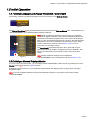
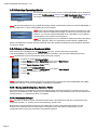
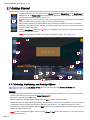
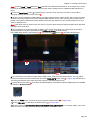
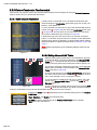
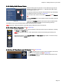
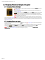
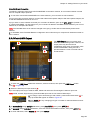
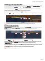
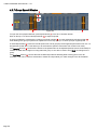
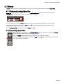
LIGHTCONVERSE User Manual - v.41
2.1.5 Assigning Objects to a Layer
To assign selected objects to a layer, press the Layer button (see [12] in Figure 10), then select the desired layer
number. Layers can be named via the Rename button in the Layer pop-up window. Note that layers can be useful
when working with large groups of objects.
Note: For using DMX controlled moving objects (Dynamic Layers), see Section 2.2.6.
2.1.6 Patching Objects to DMX (LED Surfaces, Video Screens etc.)
• 3D objects can have their individual color levels controlled by DMX (3 channel RGB; each channel includes the
object’s diffuse, specular and emissive components), for example, when using LED objects.
Note: Diffuse, specular and emissive components are set via the Material Editor, see Section 2.3.2 for more
information.
Note: There are two ways to simulate LED objects in LIGHTCONVERSE: The first method is by controlling the
RGB levels of a surface as described above, the second method is by using an actual LED fixture (selected via
the DMX Setup screen, see Chapter 3).
• 3D objects can also have only their emissive level controlled by DMX (1 channel controls the object’s emissive
component), for example, when using video screens, practical lamps, pyro, etc.
• To select 3 channel RGB or 1 channel emissive modes, press the DMX:RGB button (see [18] in Fig.10).
Objects can be patched to the DMX Input or DMX Output (see [13] in Figure 10): An object is patched to the DMX
input in order to be controlled by a console while using Visualization Only mode. An object is patched to the DMX
output while using Full Processing mode. Once patched, the object’s DMX address appears in the Room Object
List (see [3] in Figure 10).
Note: For patching Dynamic Layers to DMX (moving objects), see Section 2.2.6.
2.1.7 Centering the view on an Object
To center the camera view on an object, select the object, then press the Center button (see [7] in Figure 10).
[Hot Key = Space]
2.1.8 Setting the 3D World Center
A selected object can be set as a zero reference (0(X),0(Y),0(Z)) in the 3D world by pressing the World Center
button (see [8] in Figure 10). This may be used, for example, to make a stage a zero reference from which all
measurements are made. The default World Center location is directly in the center of the room.
Note: When an object is set as the World Center, its number in the Room Object list will turn yellow
.
2.1.9 Imperial or Metric Measurement
Press the Imperial or Metric buttons to alternate between units of measurement (see [8] in Figure 10).
2.1.10 Object Calculator Options
Located next to the Position, Rotation and Size parameters is a calculator button
options can be entered:
in which the following
+, -, *, / : Use to shift the objects’ array or change distance between objects, for example, *1.5 or /1.5. To shift an
object by its dimension value after duplicating, use Alt+Cursor.
< >: Selected objects will be distributed proportionally as per the entered distance with a positive / negative
relation to the main selected object, for example >10. If a distance is not entered, the main selected object bound
size will be used as a distribution step. Note that < > also works with angles, scale and 2D position (if no
parameter is used with angles, 360 degrees is assumed).
m,c,p : Used with a parameter value to align selection bounding with the Minus/Center/Plus relation of target
point. If no parameter value is entered, 0 is used (which is equal to World center). [Hot Keys = Alt+Numeric]
M,C,P : Used with a parameter value to align selected bounding with the Minus/Center/Plus relation of main
selected object. If no parameter value is entered, 0 is used, (useful to Snap main and other selection boundings
together. [Hot Keys = Ctrl+Numeric]
Page 12