1
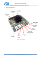
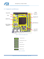
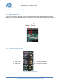
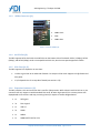
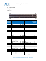
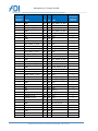
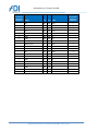
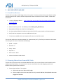
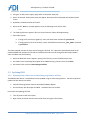
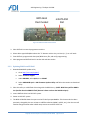
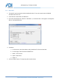
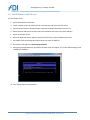
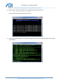
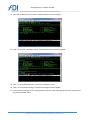
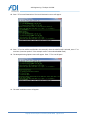
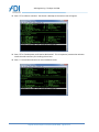
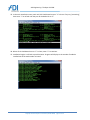
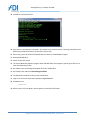
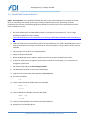
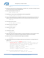
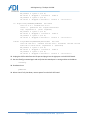
The Open IP ODM Rangeley Communications Collateral Dense Form Factor (RCC-DFF) Platform User Manual Revision: 1.01 ADI Engineering, Inc. 1758 Worth Park Charlottesville, VA 22911 www.adiengineering.com Phone: (434)-978-2888 Fax: (434)-978-1803 Document 45700-0006 ADI Engineering: The Open IP ODM Revision History Date 7/5/14 8/19/14 Revision 1.00 1.01 Remarks Initial release 1.2. Changed operating temp range. Rangeley RCC-DFF Platform User Manual (45700-0006) page 2 of 36 ADI Engineering: The Open IP ODM Table of Contents 1 RANGELEY COMMUNICATIONS COLLATERAL - DENSE FORM FACTOR (RCC-DFF) PLATFORM DESCRIPTION 4 1.1 1.2 1.3 1.4 1.5 1.5.1 1.5.2 1.5.3 1.5.4 1.5.5 1.5.6 1.5.7 1.6 1.6.1 1.6.2 1.6.3 1.6.4 1.6.5 1.6.6 2 RCC-DFF SETUP AND USE ........................................................................................................................ 16 2.1 2.2 2.3 2.3.1 2.3.2 2.4 3 OVERVIEW ................................................................................................................................................... 4 FEATURE SUMMARY ...................................................................................................................................... 5 USER PORTS REFERENCE ................................................................................................................................. 6 COMPONENT LAYOUT REFERENCE .................................................................................................................... 8 COMPONENT OVERVIEW ................................................................................................................................ 9 Rangeley SOC ....................................................................................................................................... 9 Memory ................................................................................................................................................ 9 CP2104 (USB-to-UART Bridge) ............................................................................................................. 9 SOC SPI Flash ........................................................................................................................................ 9 eMMC Flash ......................................................................................................................................... 9 TPM ...................................................................................................................................................... 9 88E1514 (GBE PHYs) and CPU EEPROM ............................................................................................. 10 CONNECTOR AND JUMPER REFERENCE ............................................................................................................ 11 Battery Header (J13) .......................................................................................................................... 11 Front Panel Connector (J12) ............................................................................................................... 11 SMBus Connector (J3) ........................................................................................................................ 12 mSATA Slot (J2) .................................................................................................................................. 12 PCIe Slots (J4, J5) ................................................................................................................................ 12 Expansion Connector (J5) ................................................................................................................... 12 SERIAL PORT DRIVERS .................................................................................................................................. 16 RUNNING FEDORA LINUX FROM EMMC FLASH ................................................................................................ 16 UPDATING BIOS ......................................................................................................................................... 17 Updating Flash with an external benchtop programmer machine .................................................... 17 Updating BIOS from EFI Shell ............................................................................................................. 18 UPDATING RANGELEY GBE EEPROM ............................................................................................................. 19 INSTALLING FEDORA LINUX (REFERENCE ONLY) ..................................................................................... 21 3.1 CREATE INSTALLATION DVD .......................................................................................................................... 21 3.1.1 Download the Fedora 19 x86_64 DVD ISO image .............................................................................. 21 3.1.2 Download ISO DVD burner software .................................................................................................. 21 3.1.3 Burn DVD............................................................................................................................................ 22 3.2 INSTALL LINUX TO MSATA CARD .................................................................................................................... 23 3.3 INSTALL INTEL NETWORK DRIVERS .................................................................................................................. 33 4 SUPPORT................................................................................................................................................ 36 Rangeley RCC-DFF Platform User Manual (45700-0006) page 3 of 36 ADI Engineering: The Open IP ODM 1 RANGELEY COMMUNICATIONS COLLATERAL - DENSE FORM FACTOR (RCCDFF) PLATFORM DESCRIPTION 1.1 Overview The Rangeley Communications Collateral – Dense Form Factor (RCC-DFF) platform is based on the Intel Rangeley SOC. Rangeley is a multi-core (up to 8) Intel Atom based SOC product featuring high levels of I/O integration and an Intel QuickAssist hardware acceleration engine. Rangeley is targeted for the routers and security communications market segment. This platform will demonstrate Rangeley in an embedded, lower power, and small form factor solution. The RCC-DFF block diagram is shown in Figure 1. WWAN Module PCIe x1 Socket Connector NCSI 2 PCIe x1 Socket Connector Bottom Side RJ45 w/ Mag RJ45 w/ Mag DDR3 CH B PCIe SATA GEN2 SATA GEN3 SGMII SGMII 88E1514 DDR3 CH A mSATA Drive 2 Rangeley/ Avoton SOC 2 or 4 core 2 PCIe 6 lanes 2 2 SGMII 88E1514 1 Mini-B USB USB UART USB UART LPC SPI JTAG USB-A TPM XDP Atom uServer Clocks Barrel Jack 12V FLASH 8MB SD/MMC Bridge eMMC 16GB Power Regs Figure 1 – RCC-DFF Block Diagram Rangeley RCC-DFF Platform User Manual (45700-0006) page 4 of 36 Custom PCIe Connector for Expansion PCIe x1 Adapter Board/ Cable CH-A 4GB Mem Down, Single Rank, x8, w/ECC ADI Engineering: The Open IP ODM 1.2 Feature Summary Feature Description Board Form Factor 8-layer Nano-ITX (120 x 120 mm) Processor 9.5W/4C default C2508 SKU. Supports all SKU’s of Rangeley and Avoton CPU up to 10W TDP. Memory Single Channel Memory Down, 4GB, DDR3L-1600 with ECC Clocking IDT 9VRS4420 for Atom-based microservers IDT 9DBU0531 for PCIe clock distribution Solid State Disk mSATA Gen2 slot Onboard eMMC flash 16GB BIOS SPI Boot Flash 8MB USB One USB 2.0 host port SOC UART One console port to CPU through a mini USB connector to UART bridge (Silicon Labs CP2104) LAN support Two 10/100/1000Base-TX Ethernet Ports (RJ-45) Debug Interface XDP 60-pin debug connector Expansion Ports Expansion daughterboard connector with: o 1x SATA gen3 o 3x PCIe x2 gen2 o 1x USB 2.0 o 2x SGMII o 1x SMBus o 1x 100MHz diff clock for PCIe o 1x MDIO (for SGMII) o 12VDC @ 2A o 3.3VDC @ 3A PCIe x1 slot Battery 2-pin header for optional separate RTC battery TPM Infineon SLB9655TT1.2 down Power Supply External 12 VDC output power supply Max 60W (when fully-loaded with expansion boards, USB, etc.) Typ 13W (eMMC, Ethernet only) 100 - 240 VAC input to power supply 50 - 60Hz Temperature Temperature is 0°C to 65°C ambient outside board. Rangeley RCC-DFF Platform User Manual (45700-0006) page 5 of 36 ADI Engineering: The Open IP ODM 1.3 User Ports Reference RTC Battery Header Expansion Connector XDP Debug Port Power/Status LED Text Front Panel Header Reset Pushbutton Power Input 12 VDC RJ-45 GBE Ports Mini-USB Serial Console Port USB 2.0 Host Port Figure 2 – User ports (top side) Rangeley RCC-DFF Platform User Manual (45700-0006) page 6 of 36 ADI Engineering: The Open IP ODM BIOS Boot Flash Socket mSATA SSD Slot PCIe x1 Slot Figure 3 – User ports (bottom side) Rangeley RCC-DFF Platform User Manual (45700-0006) page 7 of 36 ADI Engineering: The Open IP ODM 1.4 Component Layout Reference VDDQ Regulator Status LEDs TPM Rangeley SoC eMMC Flash DDR3 Memory Misc Voltage Regulators Core VR12 Regulators Figure 4 – Component Layout, Major Circuits +5 VDC +5 VDC power is good ALL PWRGD All voltage regulators are good RESET Board is in reset SPI CS SPI boot flash activity SATA mSATA slot activity EMMC eMMC flash activity Figure 5 – Status LEDs Rangeley RCC-DFF Platform User Manual (45700-0006) page 8 of 36 ADI Engineering: The Open IP ODM 1.5 Component Overview 1.5.1 Rangeley SOC The RCC-DFF system ships with the 9.5W 4 core C2508 SKU of the Rangeley SoC. Please refer to the latest Intel documentation on the SoC for the SKU features. The RCC-DFF system has been designed to be compatible with all other Rangeley SKUs equal to or less than 9.5W TDP. 1.5.2 Memory The RCC-DFF supports one channel of DDR3 in a single rank memory down with ECC. The BIOS determines memory characteristics by reading the SPD EEPROM on the board. Rangeley only supports UDIMM configurations, so the memory is routed unbuffered and the SPD EEPROM is programmed with the values used on an equivalent Micron UDIMM part number MT9KSF25672AZ-1G6K2. SPD EEPROM files for various types of DIMMs are available for download on the Micron website. The system ships with 4GB of DDR3-1600 memory. The board could support up to 8GB of memory by changing the memory down devices and SPD EEPROM image. 1.5.3 CP2104 (USB-to-UART Bridge) The RCC-DFF board has a CP2104 which is a USB-to-UART bridge. The UART is connected to the console port on the SOC. The USB is brought out to a mini-B connector on the front panel. 1.5.4 SOC SPI Flash There is a single 8MB SPI flash device connected to the SOC for boot firmware. The flash is socketed so that it can be programmed using an external benchtop programmer machine. It contains a BIOS and descriptor which is used for normal operation and can be updated with new versions. There is also an AMI update utility that can be used to update the BIOS from a USB thumbdrive at runtime, rather than physically removing the flash device from the socket. 1.5.5 eMMC Flash The SBC uses a USB-to-MMC bridge chip, the Microchip USB2241, to interface with a 16GB eMMC. The industry-standard BGA153 footprint supports multiple different densities with a BOM change. The eMMC appears to BIOS as a bootable SSD and has been preprogrammed with Fedora Linux and the necessary Ethernet network driver that supports the 88E1514 PHY. 1.5.6 TPM A Trusted Platform Module (TPM) device is soldered down on the board. The Infineon SLB9655TT1.2 is be used. Rangeley RCC-DFF Platform User Manual (45700-0006) page 9 of 36 ADI Engineering: The Open IP ODM 1.5.7 88E1514 (GBE PHYs) and CPU EEPROM The SOC is connected to two Marvell 88E1514 over SGMII-2 and SGMII-3. It configures the PHYs using a MDC/MDIO interface. The PHYs are connected to RJ45s with integrated magnetics. The SOC uses an EEPROM to configure the Ethernet MAC interfaces. The EEPROM also contains PHY configuration data. The 88E1514 can only have a PHY address of 0x00 or 0x01, due to its internally fixed upper address bits of zero; only bit 0 can be strapped to a 0 or 1. The SGMII ports were selected to facilitate clean routing and fewer PCB layers and thus do not match the PHY addresses. SGMII-2 is connected to PHY 0x00. SGMII-3 is connected to PHY 0x01. This mismatch is corrected by manually editing the CPU EEPROM image to assign the PHY address mapping differently: SGMII-0 maps to PHY 0x02. SGMII-1 maps to PHY 0x03. SGMII-2 maps to PHY 0x00. SGMII-3 maps to PHY 0x01. EEPROM word 0x13 changes from default 0x0041 to 0x0045 EEPROM word 0x93 changes from default 0x0043 to 0x0047 EEPROM word 0xD3 changes from default 0x0045 to 0x0041 EEPROM word 0x113 changes from default 0x0047 to 0x0043 These addresses correspond to register offset 0x13 “Initialization Control 4”. See Intel document 537426 “Intel® Atom™ Processor C2000 Product Family Integrated GbE Controller Programmer's Reference Manual (PRM)“ for detailed description of bit fields in this register. Note that when changing these values in the EEPROM file, the checksum words in the file must also be updated to match. This is more easily accomplished using the EEUPDATE utility to program the text .TXT version of the EEPROM file because EEUPDATE automatically recalculates and updates the checksum words when it programs the EEPROM. Please refer to ADI Engineering for the latest EEPROM .TXT file for the RCC-DFF board. Rangeley RCC-DFF Platform User Manual (45700-0006) page 10 of 36 ADI Engineering: The Open IP ODM 1.6 Connector and Jumper Reference 1.6.1 Battery Header (J13) The RCC-DFF board has a 2-pin 0.100” header that can optionally be used to attach a separate coin cell or battery pack via a custom cable for RTC support. A battery is not necessary for basic operation of the RCC-DFF board. + Battery Battery Figure 6 - Connector: Battery Header J13 1.6.2 Front Panel Connector (J12) 1 +3.3V power 2 GND for +3.3V power 3 Power button# 4 GND for power button 5 Reset button# 6 GND for reset button 7 Power LED# 8 +5V pullup for PWR LED 9 SATA LED# 10 +5V pullup for SATA LED Figure 7 - Connector: Front Panel (J2) Rangeley RCC-DFF Platform User Manual (45700-0006) page 11 of 36 ADI Engineering: The Open IP ODM 1.6.3 SMBus Connector (J3) 3 SMBus clock 2 GND 1 SMBus data Table 1 - Connector: SMBus (J3) 1.6.4 mSATA Slot (J2) The SBC supports SATA Gen2 with the mSATA slot on the bottom side of the board. SATA1 (1.5Gbps), SATA2 (3Gbps), and SATA3 (6Gbps) cards are compatible with this slot, but the max speed supported is SATA2. 1.6.5 PCIe Slots (J4, J5) The SBC supports PCIe expansion on two slots: J4 PCIe x1 gen3 slot J4 on underside of board. Can accept x1 PCIe cards. Supports 12V @ 500mA and 3.3V @ 3A. J5 I/O Expander slot J5 on top side of board (see section 1.6.6). 1.6.6 Expansion Connector (J5) The SBC provides a PCIe x16 connector that is used for I/O expansion. While it does have PCIe links on it, the connector will only support x1 width standard PCIe cards. All other high-speed I/O is a custom pinout with depopulated series resistors and caps; accessing these I/O requires a custom daughterboard. 1x SATA gen3 3x PCIe x2 gen2 1x USB 2.0 2x SGMII 1x SMBus 1x 100MHz diff clock for PCIe Rangeley RCC-DFF Platform User Manual (45700-0006) page 12 of 36 ADI Engineering: The Open IP ODM 1x 12VDC @ 2A 3.3VDC @ 3A MDIO (for SGMII) B82 B1 A82 A1 Connection Populated On Board Signal Pin Pin Signal x +12V B1 A1 NC x +12V B2 A2 +12V x x +12V B3 A3 +12V x x GND B4 A4 GND x x SMBus clock B5 A5 4.75k pulldown x x SMBus data B6 A6 4.75k pullup to3.3V x x GND B7 A7 NC x +3.3V B8 A8 4.75k pullup to3.3V x x 4.75k pulldown B9 A9 +3.3V x x +3.3V B10 A10 +3.3V x x WAKE# B11 A11 RESET# x NC B12 A12 GND x x GND B13 A13 100 MHz clock DP x x PCIE_PORT0_TX_DP0 B14 A14 100 MHz clock DN x x PCIE_PORT0_TX_DN0 B15 A15 GND x x GND B16 A16 PCIE_PORT0_RX_DP0 x NC B17 A17 PCIE_PORT0_RX_DN0 x x GND B18 A18 GND x x PCIE_PORT0_TX_DP1 B19 A19 NC x PCIE_PORT0_TX_DN1 B20 A20 GND x x GND B21 A21 PCIE_PORT0_RX_DP1 x x GND B22 A22 PCIE_PORT0_RX_DN1 x PCIE_PORT1_TX_DP0 B23 A23 GND x PCIE_PORT1_TX_DN0 B24 A24 GND x GND B25 A25 PCIE_PORT1_RX_DP0 x Connection Populated On Board Rangeley RCC-DFF Platform User Manual (45700-0006) page 13 of 36 ADI Engineering: The Open IP ODM Connection Populated On Board Signal Pin Pin Signal x GND B26 A26 PCIE_PORT1_RX_DN0 PCIE_PORT1_TX_DP1 B27 A27 GND x PCIE_PORT1_TX_DN1 B28 A28 GND x GND B29 A29 PCIE_PORT1_RX_DP1 NC B30 A30 PCIE_PORT1_RX_DN1 NC B31 A31 GND GND B32 A32 NC PCIE_PORT2_TX_DP0 B33 A33 NC PCIE_PORT2_TX_DN0 B34 A34 GND x GND B35 A35 PCIE_PORT2_RX_DP0 x GND B36 A36 PCIE_PORT2_RX_DN0 PCIE_PORT2_TX_DP1 B37 A37 GND x PCIE_PORT2_TX_DN1 B38 A38 GND x x GND B39 A39 PCIE_PORT2_RX_DP1 x GND B40 A40 PCIE_PORT2_RX_DN1 SGMII_PORT0_TX_DP B41 A41 GND x SGMII_PORT0_TX_DN B42 A42 GND x x GND B43 A43 SGMII_PORT0_RX_DP x GND B44 A44 SGMII_PORT0_RX_DN SGMII_PORT1_TX_DP B45 A45 GND x SGMII_PORT1_TX_DN B46 A46 GND x GND B47 A47 SGMII_PORT1_RX_DP NC B48 A48 SGMII_PORT1_RX_DN GND B49 A49 GND NC B50 A50 NC NC B51 A51 GND x GND B52 A52 USB_DP x GND B53 A53 USB_DN SATA3G_TX_DP B54 A54 GND x SATA3G_TX_DN B55 A55 GND x x GND B56 A56 SATA3G_RX_DP x GND B57 A57 SATA3G_RX_DN NC B58 A58 GND x NC B59 A59 GND x x GND B60 A60 NC x GND B61 A61 NC NC B62 A62 GND x x x x Connection Populated On Board Rangeley RCC-DFF Platform User Manual (45700-0006) page 14 of 36 x x x x x ADI Engineering: The Open IP ODM Connection Populated On Board Signal Pin Pin Signal Connection Populated On Board NC B63 A63 GND x x GND B64 A64 NC x GND B65 A65 NC NC B66 A66 GND x NC B67 A67 GND x x GND B68 A68 NC x GND B69 A69 NC MDIO_CLK B70 A70 GND x MDIO_DATA B71 A71 GND x x GND B72 A72 NC x GND B73 A73 NC NC B74 A74 GND x NC B75 A75 GND x x GND B76 A76 NC x GND B77 A77 NC NC B78 A78 GND x USB overcurrent# B79 A79 GND x GND B80 A80 NC x NC B81 A81 NC x NC B82 A82 GND Rangeley RCC-DFF Platform User Manual (45700-0006) page 15 of 36 x ADI Engineering: The Open IP ODM 2 RCC-DFF SETUP AND USE 2.1 Serial Port Drivers The RCC-DFF has a USB-to-UART bridge for the CPU console. The device used is a Silicon Labs CP2104. Before connecting the RCC-DFF system, the host computer will need to install drivers for the CP2104. Follow these instructions: 1. Go to the following address: uart-bridge.aspx http://www.silabs.com/products/interface/usbtouart/Pages/usb-to- 2. Select Tools tab. 3. Select drivers for your OS. For Windows, select CP210x_VCP_Windows.zip 4. Download and follow instructions for installing driver 5. Use the provided USB Mini-B cable and connect the RCC-DFF system console to the host computer 6. Verify that host computer can see one additional serial port 7. The serial port added to the host computer will connect to the CPU console. The user will need to use a terminal emulator (i.e. Hyperterminal, PuTTy, TeraTerm) to connect to the console. The settings for the terminal should be the following: Speed = 115,200 Data Bits = 8 Parity = None Stop Bits = 1 Flow Control = None Preferred emulation mode is ANSI 2.2 Running Fedora Linux From eMMC Flash The RCC-DFF system comes with an onboard eMMC flash drive with a custom Fedora Linux installation and is ready to use out of the box. For instructions on how to create Fedora Linux with Rangeley patches and Ethernet drivers, please refer to section 3. 1. Connect User Interface. Two options: a. CPU console port over USB-to-UART bridge b. PCIe x1 Graphics Card in PCIe slot (either J4 or J5), external USB hub, USB Keyboard and mouse plugged into USB hub. Rangeley RCC-DFF Platform User Manual (45700-0006) page 16 of 36 ADI Engineering: The Open IP ODM 2. Using the 12 VDC power supply, apply power to the power input jack. 3. Wait 5-20 seconds. BIOS splash screen will appear. No output will be displayed until the BIOS splash screen. 4. By default, the BIOS will boot to EFI shell. 5. When the EFI Shell> prompt appears, enter the following to exit the EFI shell: exit 6. The Fedora grub menu appears. After a 3-second timeout, Fedora will begin booting. 7. After Fedora boots: a. If using serial console (not graphics), enter username root. Password is password. b. If using graphics (not serial console), accept the default username rcc_dff_emmc. Password is password. The above method includes the extra step of exiting the EFI shell. If it is desired to automatically boot to the onboard eMMC flash without the EFI shell, the default boot order must be changed in BIOS setup. Replace steps 4-5 above with the following: 1. When the BIOS flash screen appears, quickly press ESC key to enter the BIOS setup screen. 2. Go to Boot menu and change Boot Option #1 to eMMC flash (e.g. Generic Ultra HS-COMBO). 3. Go to Save & Exit and select Save Changes and Exit. 2.3 Updating BIOS 2.3.1 Updating Flash with an external benchtop programmer machine The 8MB SPI flash device is socketed and can be updated using an external programmer. The tools required to update the flash devices are below: External flash programmer machine with SOIC8 (208mil) adapter. SPI Flash binary with descriptor and BIOS. Available from Intel and ADI. Instructions for updating SPI Flash 1. Turn off power to RCC-DFF system. 2. Open socket at location U19 and remove SPI flash. See Figure 8 for location. Rangeley RCC-DFF Platform User Manual (45700-0006) page 17 of 36 ADI Engineering: The Open IP ODM BIOS Boot Flash Socket mSATA SSD Slot Figure 8 – BIOS boot flash socket location 3. Place SPI flash in external programmer machine. 4. Select device type W25Q64xV where the “x” denotes revision. Any revision B, C, F, etc. will work. 5. Erase SPI flash, program with descriptor/BIOS binary file, and verify programming. 6. Place programmed SPI flash back in socket U19 and close socket. 2.3.2 Updating BIOS from EFI Shell 1. Download AMI BIOS update utility a. Go to http://ami.com/support/ b. Select Technical Support c. Under AMIBIOS, select Aptio, then SUBMIT PCIe x1 Slot d. Select AMIBIOS & Aptio – AMI Firmware Update Utility and follow instructions to download utility. 2. Place this utility on a USB flash drive along with the BIOS binary. (NOTE: BIOS binary will be 6MB in size (smaller than the 8MB SPI flash) because it does not have the 2MB descriptor). 3. Insert USB flash drive into RCC-DFF system. 4. Power on RCC-DFF system 5. The BIOS will default boot the system to the EFI shell prompt Shell>. If the boot order has been previously changed by the user to boot to a different device (eMMC, mSATA, etc.), then the user will need to change the boot order in BIOS setup screens to make EFI shell first. Rangeley RCC-DFF Platform User Manual (45700-0006) page 18 of 36 ADI Engineering: The Open IP ODM 6. The USB flash drive will be identified as a fs device in EFI shell and labeled as a Removable HardDisk. In this example, the USB flash drive is fs0. EFI Shell version 2.31 [5.8] Current running mode 1.1.2 Device mapping table fs0 :Removable BlockDevice - Alias f19b0e0 blk0 PciRoot(0x0)/Pci(0x16,0x0)/USB(0x1,0x0)/USB(0x4,0x0) blk0 :Removable BlockDevice - Alias f19b0e0 fs0 PciRoot(0x0)/Pci(0x16,0x0)/USB(0x1,0x0)/USB(0x4,0x0) blk1 :Removable HardDisk - Alias (null) PciRoot(0x0)/Pci(0x16,0x0)/USB(0x1,0x0)/USB(0x3,0x0)/HD(1,MBR,0x0002A123,0x80 0,0xFA000) blk2 :Removable HardDisk - Alias (null) PciRoot(0x0)/Pci(0x16,0x0)/USB(0x1,0x0)/USB(0x3,0x0)/HD(2,MBR,0x0002A123,0xFA 800,0x1BD5800) blk3 :Removable BlockDevice - Alias (null) PciRoot(0x0)/Pci(0x16,0x0)/USB(0x1,0x0)/USB(0x3,0x0) Press ESC in 1 seconds to skip startup.nsh, any other key to continue. Shell> 7. Go to USB flash drive. fs0: 8. Go (cd) to the folder with the BIOS update utility and BIOS binary. 9. Start the BIOS update process. Filename.rom is the BIOS file. AfuEfix64.efi filename.rom /p /b /n 10. Wait for utility to complete. DO NOT CYCLE POWER DURING UPDATE. 11. Once update is complete, cycle power. 2.4 Updating Rangeley GbE EEPROM NOTE: Very Important. Read all of section 1.5.7 regarding special edits that must be made to the GBE EEPROM image file to be compatible with the RCC-DFF board. The RCC-DFF has an onboard eMMC flash drive that is preprogrammed with Fedora Linux, network drivers compatible with the 88E1514 Ethernet PHYs, and the Intel EEUPDATE and LANCONF utilities. The instructions in this section assume the use of the existing eMMC Linux installation and Intel utilities. Programming the Rangeley RCC-DFF Platform User Manual (45700-0006) page 19 of 36 ADI Engineering: The Open IP ODM EEPROM from EFI shell or another drive will require a separate installation of the latest Intel Network Connection Tools from the Intel Business Portal (IBP) (Document #348742). 1. Copy the Rangeley EEPROM update file to a USB flash drive. File should be in text format. 2. Insert USB flash drive into RCC-DFF system. 3. Power on RCC-DFF system 4. Boot to Fedora Linux as user root on the eMMC flash as described in section 2.2. 5. Go to the folder with the eeupdate64ei update utility and EEPROM text file. cd ../rcc/lantools/OEM_Mfg 6. Identify Rangeley GBE ports using the EEUPDATE utility. ./eeupdate64e 4 ports will be identified as NICs 1-4. Rangeley ports are identified by Vendor-Device 8086-1F41. Using: Intel (R) PRO Network Connections SDK v2.23.8 EEUPDATE v5.23.13.00 Copyright (C) 1995 - 2014 Intel Corporation Intel (R) Confidential and not for general distribution. Warning: No Adapter Selected NIC Bus Dev Fun Vendor-Device Branding string === === === === ============= ================================================= 1 0 20 00 8086-1F41 Intel(R) Ethernet Connection 2 0 20 01 8086-1F41 Intel(R) Ethernet Connection 3 0 20 02 8086-1F41 Intel(R) Ethernet Connection 4 0 20 03 8086-1F41 Intel(R) Ethernet Connection I354 I354 I354 I354 [root@localhost OEM_Mfg]# 7. To update the Rangeley EEPROM, NIC #1 should be selected in the update command. Below is an example of the update command. Filename.txt is the EEPROM programming file. ./eeupdate64e /nic=1 /d filename.txt 8. Wait for command to complete and verify it reports successful. DO NOT CYCLE POWER DURING UPDATE. 9. Shutdown Linux. poweroff 10. When Linux is fully powered down, power cycle the RCC-DFF board. Note that the new EEPROM programming changes will not be read in by the Rangeley CPU until power is cycled. Rangeley RCC-DFF Platform User Manual (45700-0006) page 20 of 36 ADI Engineering: The Open IP ODM 3 INSTALLING FEDORA LINUX (REFERENCE ONLY) NOTE: The following sections describe installation of Fedora Linux to a removable mSATA card. The same procedure can also be used to overwrite the existing Fedora Linux installation on the onboard eMMC flash. To use this procedure for the eMMC flash, do not insert a mSATA card and make sure to select the eMMC as the Install Destination in section 3.2 3.1 Create installation DVD The Fedora 19 installation guide can be found at http://docs.fedoraproject.org/enUS/Fedora/19/html/Installation_Guide/index.html. The following sections describe how to create the installation DVD using a Windows PC. 3.1.1 Download the Fedora 19 x86_64 DVD ISO image Note: In this section, be sure to download the “full” DVD ISO installation image (3-5GB). Do not download the smaller “live” DVD ISO installation image (< 1GB). Note: Download times can be several hours, depending on internet connection bandwidth, so plan accordingly. 1. Navigate to http://download.fedoraproject.org/pub/fedora/linux/releases/19/Fedora/x86_64/iso/Fedora-19x86_64-DVD.iso. 2. Choose the option to save ISO image to local PC. 3. Download the ISO image to local PC hard drive. This image will be approximately 4GB. 3.1.2 Download ISO DVD burner software 1. Download the freeware Active ISO DVD burner software at http://www.ntfs.com/iso_burner_free.htm. 2. Install software to local PC hard drive. Rangeley RCC-DFF Platform User Manual (45700-0006) page 21 of 36 ADI Engineering: The Open IP ODM 3.1.3 Burn DVD 1. The local PC may have a built-in DVD writeable disc drive. If not, then attach external USB DVD writeable disc drive to PC. 2. Insert DVD +R or DVD-R disk into DVD drive. 3. Start Active ISO DVD burner software. In Windows 7, it is found at Start > All Programs > Active@ ISO Burner > Active@ ISO Burner. 4. Procedure: a. For the Source, select the Fedora-19-x86_64-DVD.iso file from the local HDD. b. For the Target, select the external DVD burner. c. Mode = Track at Once d. Speed = Auto Select e. Copies = 1 5. Click on the Burn button. This step may take several minutes. Rangeley RCC-DFF Platform User Manual (45700-0006) page 22 of 36 ADI Engineering: The Open IP ODM 3.2 Install Linux to mSATA card To install Fedora Linux: 1. Power down the RCC-DFF board. 2. Install a mSATA card in the mSATA slot J2 on the bottom side of the RCC-DFF board. 3. Connect serial console to board and open a terminal window as described in section 2.1. 4. Attach external USB DVD drive with Fedora 19 installation disc to the front panel USB port. 5. Power up RCC-DFF board. 6. When the BIOS flash screen appears, quickly press ESC key to enter the BIOS setup screen. 7. Go to Boot menu and change Boot Option #1 to the external USB drive. 8. Go to Save & Exit and select Save Changes and Exit. 9. After going through BIOS boot, the Fedora 19 setup screen will appear. This screen allows editing of the installation parameters. 10. Press TAB to edit the command line. Rangeley RCC-DFF Platform User Manual (45700-0006) page 23 of 36 ADI Engineering: The Open IP ODM 11. Delete “quiet” from the command line and append the following at the end text console=ttyS1,115200n8 so that it looks like the following and press Enter. 12. The Linux installation begins. An installation image check will start running showing percent complete at the bottom. Rangeley RCC-DFF Platform User Manual (45700-0006) page 24 of 36 ADI Engineering: The Open IP ODM 13. Press ESC to abort check. The main Installation options menu will appear. 14. Enter “1” enter for installation source. The Installation source menu will appear. 15. Enter “1” for CD/DVD and return to the main installation menu. 16. Enter “2” for timezone settings. The timezone settings menu will appear. 17. In the timezone settings menu, select appropriate country, then select appropriate zone, and return to the main installation menu. Rangeley RCC-DFF Platform User Manual (45700-0006) page 25 of 36 ADI Engineering: The Open IP ODM 18. Enter “3” for Install Destination. The Install Destination menu will appear. 19. Enter “1” for the mSATA card (64 GB in this example). Once the mSATA card is selected, enter “c” to continue. (note that option 2 in the example screen is the onboard eMMC flash). 20. The Autopartitioning Options menu will appear. Enter “2” for Use All Space. 21. The main installation menu will appear. Rangeley RCC-DFF Platform User Manual (45700-0006) page 26 of 36 ADI Engineering: The Open IP ODM 22. Enter “4” for Create User. The Create User menu will appear. 23. Enter “1” to create user. 24. Enter “3” for username. The username prompt will appear. 25. Enter desired username (“rcc_dff” in this example). Rangeley RCC-DFF Platform User Manual (45700-0006) page 27 of 36 ADI Engineering: The Open IP ODM 26. Enter “4” for use password, then “5” for enter password. 27. Enter password “password” twice to confirm. 28. Enter “6” for administrator. Rangeley RCC-DFF Platform User Manual (45700-0006) page 28 of 36 ADI Engineering: The Open IP ODM 29. Enter “c” to continue back to main installation screen. 30. Enter “5” for set root password. 31. Enter password “password” twice to confirm, confirm that yes it is a weak password, and return to main installation menu. Rangeley RCC-DFF Platform User Manual (45700-0006) page 29 of 36 ADI Engineering: The Open IP ODM 32. Enter “6” for software selection. The Choose a desktop environment menu will appear. 33. Enter “8” for “Development and Creative Workstation”. This is important, because that selection installs the tools necessary for installing drivers later. 34. Enter “c” to continue and return to main installation menu. Rangeley RCC-DFF Platform User Manual (45700-0006) page 30 of 36 ADI Engineering: The Open IP ODM 35. In the main installation menu, wait until all 6 checkboxes have an “x” in them. If any say “processing”, then enter “r” to refresh until they are all checked with an “x”. 36. When all six checkboxes have an “x” in them, enter “c” to continue. 37. Installation begins. It will take up to 60 minutes. Progress will display as the number of modules installed out of the total number to install. Rangeley RCC-DFF Platform User Manual (45700-0006) page 31 of 36 ADI Engineering: The Open IP ODM 38. Installation eventually finishes. 39. Press enter to complete the installation. The installer may reset the system, returning eventually to the BIOS setup prompt. Alternately, the installer may just stop. 40. Either way, power off the RCC-DFF board before it boots from USB DVD drive again. 41. Detach USB DVD drive. 42. Power on RCC-DFF board. 43. The normal BIOS boot sequence begins. When the BIOS flash screen appears, quickly press ESC key to enter the BIOS setup screen. 44. Go to Boot menu and change Boot Option #1 to the mSATA drive. 45. Go to Save & Exit and select Save Changes and Exit. 46. The board will now boot to Linux on the mSATA drive. 47. Login to Linux as user root with a password of password. 48. Shutdown Linux. poweroff 49. When Linux is fully shut down, remove power from the RCC-DFF board. Rangeley RCC-DFF Platform User Manual (45700-0006) page 32 of 36 ADI Engineering: The Open IP ODM 3.3 Install Intel Network Drivers NOTE: Very important. Since the RCC-DFF board does not have an onboard battery for the Real Time Clock (RTC), it is necessary to manually set the current date in the BIOS setup screen. Otherwise, the driver installation files will have a timestamp significantly different from other files in the Linux filesystem and the driver installation may fail. 1. Go to the following link and download the latest “Intel Ethernet Connections CD”. This is a large download (77MB for the v19.1 release). https://downloadcenter.intel.com/Detail_Desc.aspx?agr=Y&DwnldID=22283&keyword=18.8.1&lang=e ng 2. Inside the folder tree inside the driver zip file, the Linux GBE driver is in folder \PRO1000\LINUX. At the time this document was written, the latest driver archive was igb-5.2.5.tar.gz. Newer versions may be available. 3. Copy the igb-5.2.5.tar.gz file to a USB thumbdrive. 4. Power on the RCC-DFF board. 5. When the BIOS flash screen appears, quickly press ESC key to enter the BIOS setup screen. 6. In the main setup screen, change the system date to match the current date. It is not necessary to change the system time. 7. Go to Save & Exit and select Save Changes and Exit. 8. The board will now boot to Linux on the mSATA drive. 9. Login to Linux as user root with a password of password. 10. Go to the root folder. cd .. 11. Create a tools and drivers folder and enter that folder. mkdir rcc cd rcc 12. Create a GBE driver subfolder and enter that folder. mkdir igb cd igb 13. Insert the USB thumbdrive into the RCC-DFF board USB port. 14. Display the list of available drives. Rangeley RCC-DFF Platform User Manual (45700-0006) page 33 of 36 ADI Engineering: The Open IP ODM fdisk –l 15. Determine the drive letter of the USB thumbdrive. It should be “sdc”, since there are already 2 drives in the system sda (mSATA card) and sdb (eMMC flash). 16. Mount the USB thumbdrive to folder /mnt. mount /dev/sdc /mnt 17. Copy the driver archive from the USB thumbdrive to the current igb folder. cp /mnt/ igb-5.2.5.tar.gz . 18. If this is a new installation with no existing Intel network drivers, then proceed to step 19. If this is an update to previously-installed network drivers, then first remove the older drivers from the kernel. rmmod igb 19. Untar/unzip the driver archive. tar zxf igb-5.2.5.tar.gz 20. Change to the driver source folder. cd igb-5.2.5/src 21. Compile the driver module. make install 22. Load the driver module. modprobe igb 23. Plug a CAT5e cable from the left RJ-45 GBE port on the RCC-DFF board to a local LAN switch or router that has a DHCP server on it (DHCP server assigns IP addresses to devices on the network). 24. Check to see if the port is linked and has been assigned an IP address. ifconfig 25. In the resulting output from the ifconfig command, port em1 shows that it is running and has an IP address (inet). em1: flags=4163<UP,BROADCAST,RUNNING,MULTICAST> mtu 1500 inet 192.168.1.47 netmask 255.255.255.0 broadcast 192.168.1.255 inet6 fe80::208:a2ff:fe09:19c2 prefixlen 64 scopeid 0x20<link> ether 00:08:a2:09:19:c2 txqueuelen 1000 (Ethernet) RX packets 3 bytes 1240 (1.2 KiB) RX errors 0 dropped 0 overruns 0 frame 0 TX packets 22 bytes 4010 (3.9 KiB) TX errors 0 dropped 0 overruns 0 carrier 0 collisions 0 em2: flags=4099<UP,BROADCAST,MULTICAST> mtu 1500 ether 00:08:a2:09:19:c3 txqueuelen 1000 (Ethernet) Rangeley RCC-DFF Platform User Manual (45700-0006) page 34 of 36 ADI Engineering: The Open IP ODM RX RX TX TX packets 0 bytes 0 (0.0 B) errors 0 dropped 0 overruns 0 frame 0 packets 0 bytes 0 (0.0 B) errors 0 dropped 0 overruns 0 carrier 0 collisions 0 lo: flags=73<UP,LOOPBACK,RUNNING> mtu 65536 inet 127.0.0.1 netmask 255.0.0.0 inet6 ::1 prefixlen 128 scopeid 0x10<host> loop txqueuelen 0 (Local Loopback) RX packets 0 bytes 0 (0.0 B) RX errors 0 dropped 0 overruns 0 frame 0 TX packets 0 bytes 0 (0.0 B) TX errors 0 dropped 0 overruns 0 carrier 0 collisions 0 virbr0: flags=4099<UP,BROADCAST,MULTICAST> mtu 1500 inet 192.168.122.1 netmask 255.255.255.0 broadcast 192.168.122.255 ether 82:c1:3f:16:56:52 txqueuelen 0 (Ethernet) RX packets 0 bytes 0 (0.0 B) RX errors 0 dropped 0 overruns 0 frame 0 TX packets 0 bytes 0 (0.0 B) TX errors 0 dropped 0 overruns 0 carrier 0 collisions 0 26. Unplug the CAT5e cable from the left port and plug it into the right port on the RCC-DFF board. 27. Run the ifconfig command again and verify that the second port is running and has an IP address. ifconfig 28. Shutdown Linux. poweroff 29. When Linux is fully shut down, remove power from the RCC-DFF board. Rangeley RCC-DFF Platform User Manual (45700-0006) page 35 of 36 ADI Engineering: The Open IP ODM 4 SUPPORT Support related to the RCC-DFF system (i.e. Hardware, BIOS, Firmware, etc..) will be provided by ADI Engineering. Each kit comes with a standard support package which includes free technical support (up to 3 hours) from the engineering team and unlimited access to ADI’s web-based support forums and download site. Some customers may need extra support to handle hardware or software development tasks such as systemlevel design issues when integrating an ADI product into a larger system (thermal, regulatory, mechanical, etc.), software porting, debug or testing efforts, or design customization. Customers may also require design review or consulting services to quickly ramp up their engineering and manufacturing teams. For these customers ADI offers a variety of support packages to meet their specific requirements. Support Package Key Features ADI Part Number Standard Development Kit Support 90 day standard kit warranty Unlimited access to ADI’s web-based support site Phone & Email Support during warranty and support period (3 business day response) Up to 3 hours of support problem solving during the support period DKSS Premium Development Kit Support Extends product warranty and support period to 1 year Unlimited access to ADI’s web-based support site Phone & Email Support during warranty and support period (1 business day response) Up to 40 hours of support problem solving and hardware/software engineering assistance during the support period DKPS-040 Hourly Support Packages Up to 8 hours of support problem solving and engineering assistance over 1 year HSP-008 Up to 16 hours of support problem solving and engineering assistance over 1 year HSP-016 Up to 40 hours of support problem solving and engineering assistance over 1 year HSP-040 Up to 100 hours of support problem solving and engineering assistance over 1 year HSP-100 Up to 400 hours of support problem solving and engineering assistance over 1 year HSP-400 Up to 1000 hours of support problem solving and engineering assistance over 1 year HSP-1000 Table 2 - ADI Support Plans For questions related to the Intel SoC silicon, please contact your Intel representative. Rangeley RCC-DFF Platform User Manual (45700-0006) page 36 of 36


![LEGASIC IrCOMMアダプタPro Plus[ 137KB]](http://vs1.manualzilla.com/store/data/006589505_2-7f310eff1596309770aaa67c0dbcdaf0-150x150.png)