1
PROMENTUM®
ATCA Firmware and Software Update Instructions
October 2011
007-03278-0009
Revision history
Version
-0000
-0001
-0002
-0003
-0004
-0005
-0006
-0007
-0008
-0009
Date
May 2008
October 2008
January 2009
March 2009
July 2009
November 2009
August 2010
November 2010
June 2011
October 2011
Description
First edition.
Second edition. Minor revisions.
Third edition. Several updates
Fourth edition. Minor updates.
Fifth edition. Several updates.
Sixth edition. Minor revisions.
Seventh edition. Multiple revisions.
Eighth edition. Miscellaneous updates.
Ninth edition. Multiple updates.
Tenth edition. See What’s new in this manual on page 5 for details about changes in this version.
© 2008‐2011 by Radisys Corporation. All rights reserved. Radisys and Promentum are registered trademarks of Radisys Corporation. All other trademarks, registered trademarks, service marks, and trade names are the property of their respective owners.
Table of Contents
Preface ................................................................................................................................................ 5
About this manual........................................................................................................................................5
What’s new in this manual...........................................................................................................................5
Where to get more product information .......................................................................................................5
About related Radisys products...................................................................................................................5
Related documents......................................................................................................................................6
Notational conventions ................................................................................................................................6
Electrostatic discharge ................................................................................................................................6
Chapter 1: Introduction to the update process................................................................................ 7
Overview of the update process ..................................................................................................................8
Upgrade support policy..............................................................................................................................11
Chapter 2: Performing an update using rfw-update...................................................................... 13
Step 1: Plan the update .............................................................................................................................13
Step 2: Obtain the update bundles from Radisys ......................................................................................17
Step 3: Prepare the Linux host ..................................................................................................................18
Step 4: Update IPMC FPGA devices.........................................................................................................20
Step 5: Create a configuration file (conf.rfw) .............................................................................................21
Step 6: Update the AMC-7211 and AMC-7212 .........................................................................................25
Step 7: Run the rfw-update utility ..............................................................................................................26
Step 8: Rediscover the shelf......................................................................................................................29
Step 9: Update remaining components .....................................................................................................30
Chapter 3: Using rsys-update for single product updates ........................................................... 31
rsys-update command options...................................................................................................................32
rsys-update help ........................................................................................................................................33
Using URLs with rsys-update ....................................................................................................................33
Using full path lists.....................................................................................................................................34
Using local directories ...............................................................................................................................34
Updating all redundant components on a single module...........................................................................34
Updating non-redundant devices...............................................................................................................35
Chapter 4: Updating ATCA-45xx CPMs .......................................................................................... 37
Installing the required OS RPM packages.................................................................................................37
Installing the BIOS update driver for rsys-update ......................................................................................41
3
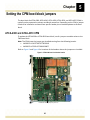
Chapter 5: Setting the CPM boot block jumpers ........................................................................... 43
ATCA-4300 and ATCA-4310 CPM ............................................................................................................43
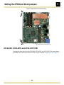
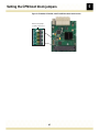
ATCA-4500, ATCA-4550, and ATCA-4555 CPM ......................................................................................44
Chapter 6: Board-level updates for the ATCA-45xx CPM and RTM ............................................. 46
Updating the BIOS.....................................................................................................................................46
Updating the IPMI firmware and FPGA for ATCA-4500, ATCA-4550, and ATCA-4555 ............................48
Updating the IPMI firmware for ATCA-4580 ..............................................................................................50
Updating the CPM FRU.............................................................................................................................53
Updating the EEPROM for ATCA-4500, ATCA-4550, ATCA-4555 ...........................................................54
Updating the EEPROM for ATCA-4580.....................................................................................................56
Updating the SAS firmware for ATCA-4580 ..............................................................................................57
Updating the legacy FPGA and SPI flash for ATCA-4500, ATCA-4550, and ATCA-4555.........................58
Updating the RTM MMC firmware, FRU, and alarm CPLD .......................................................................60
Updating the RTM SAS firmware...............................................................................................................65
Downgrading a CPM to an earlier firmware version ..................................................................................66
Chapter 7: Updating and customizing FRU data ........................................................................... 68
Customizing FRU-specific data .................................................................................................................68
Updating FRU data using fru_update ........................................................................................................70
Chapter 8: Updating IPMI FW and FRU data for an AMC or RTM................................................. 72
Determining the IPMI firmware version......................................................................................................72
Updating the IPMI firmware .......................................................................................................................73
Reverting to backup firmware....................................................................................................................74
Updating AMC or RTM FRU data ..............................................................................................................75
Chapter 9: Installing previous firmware or software versions ..................................................... 76
rfw-merge command details ......................................................................................................................76
Appendix A: Sample conf.rfw file ................................................................................................... 78
Configuration file syntax ............................................................................................................................78
Formatting guidelines for conf.rfw .............................................................................................................80
Small sample conf.rfw file..........................................................................................................................82
Full sample conf.rfw file .............................................................................................................................83
Appendix B: IPMB and IPMB-L address mapping ......................................................................... 85
Appendix C: Power cycling after IPMC FPGA upgrades .............................................................. 88
4
Preface
About this manual
ATCA systems running Promentum version 3.5.0 or earlier must be upgraded to version 4.0.0 by following the Promentum 3.x to 4.x Firmware and Software Upgrade/Downgrade Instructions.
The update instructions in this document can be used only after all system modules have been upgraded from Promentum version 3.x to version 4.0.0.
What’s new in this manual
•
•
•
Added the contents of the ATCA‐4500, ATCA‐4550, ATCA‐4555 FW‐SW Upgrade Instructions and the ATCA‐4580 FW‐SW Upgrade Instructions
Added power cycle requirements for IPMC FPGA upgrades (Appendix C)
Added the upgrade compatibility support policy (Appendix D)
Where to get more product information
Visit the Radisys Web site at www.radisys.com for product information and other resources. Downloads (manuals, release notes, software, etc.) are available at www.radisys.com/downloads.
For additional information about new features, resolved issues, and known limitations in the latest Promentum software release, refer to the Promentum product release notes.
See the following documents for additional firmware and software update information:
• Promentum 3.x to 4.x Firmware and Software Upgrade/Downgrade Instructions
• Promentum ATCA Firmware and Software Update Instructions using the Radisys Software Management Framework
For information about the PCI Industrial Computer Manufacturers Group (PICMG®) and the AdvancedTCA standard, consult the PICMG Web site at this URL: http://www.picmg.org.
About related Radisys products
For information on the Promentum product family and other Radisys products, see the Radisys Web site at www.radisys.com. 5
Preface
Related documents
•
•
Promentum 3.x to 4.x Firmware and Software Upgrade/Downgrade Instructions
Promentum ATCA Firmware and Software Update Instructions using the Radisys Software Management Framework
Notational conventions
This manual uses the following conventions
BoldText
A keyword. ItalicText
File, function, and utility names. MonoText
Screen text and syntax strings. BoldMonoText
A command to enter. ItalicMonoText
Variable parameters. Brackets [ ]
Command options. Curly braces { }
A grouped list of parameters. Vertical line |
An “OR” in the syntax. Indicates a choice of parameters. All numbers are decimal unless otherwise stated.
Electrostatic discharge
WARNING! Radisys products contain static‐sensitive components and should be handled with care. Failure to employ adequate anti‐static measures can cause irreparable damage to components.
Electrostatic discharge (ESD) damage can result in partial or complete device failure, performance degradation, or reduced operating life. To avoid ESD damage, the following precautions are strongly recommended. • Keep each module/PCB in its ESD shielding bag until you are ready to install it.
• Before touching a module, attach an ESD wrist strap to your wrist and connect its other end to a known ground. • Handle modules only in an area that has its working surfaces, floor coverings, and chairs connected to a known ground.
• Hold modules only by their edges and mounting hardware. Avoid touching PCB components and connector pins.
For further information on ESD, visit www.radisys.com/esd.
6
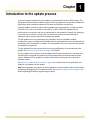
Chapter
1
Introduction to the update process
A remote firmware update utility, rfw‐update, is provided with the latest ATCA release. The rfw‐update utility remotely invokes instances of the rsys‐update tool on specified modules for significantly faster and easier updates of firmware and software components.
Using rfw‐update, shelf‐ and system‐wide upgrades can be initiated with a single command from one host, such as an external Linux host or an ATCA‐4500 CPM. Updates can be performed on live systems, and the only downtime for the modules is typically for rebooting to activate the new code. In some cases, a module may need to be reinserted and an additional reboot may be required to complete the update.
The rfw‐update utility can update both the redundant and non‐redundant module components. It uses a configuration file defined by the update administrator that identifies all Promentum ATCA components to update. The rsys‐update utility then systematically updates the identified components. The rfw‐update utility also ensures that the running configuration is preserved across the update. See Save your configuration on page 15 for details.
The rsys‐update utility inspects existing software and firmware versions so it can determine the best order to upgrade components and skip components that already have the latest version. Modules can be updated in parallel, dramatically reducing the time required to update a system.
See About rsys‐update and rfw‐update on page 8 for a detailed list of the capabilities and usage for rsys‐update and rfw‐update.
Note: Some upgrades may require an initial upgrade to an intermediate release version before completing the upgrade to the intended version. See Upgrade support policy on page 11 for details regarding the Radisys upgrade support policy.
7
Introduction to the update process
1
Overview of the update process
Using rfw-update to update one or more Promentum shelves
The basic procedure for updating one or more Promentum shelves is as follows. Additional information about each step is provided in this document.
1. Plan the update by reading this document and identifying the products to update. See page 13.
2. Obtain the update bundles from Radisys. See page 17.
3. Prepare the Linux host where rfw‐update will be run. See page 18.
4. Update IPMC FPGA devices where required. See page 20.
5. Create a configuration file to identify the Promentum ATCA products to update, along with their IP addresses and basic update order. See page 21.
6. Run the rfw‐update utility to start the update. See page 26.
Note: The rsys‐update utility can still be used for individual module updates. See page 31.
7. From the ATCA‐2210 SCM that is running the active Shelf Manager, issue a rediscoverShelf command to make sure the HPI RPT information is synchronized with the new versions running in the system. See page 29.
About rsys-update and rfw-update
rsys-update
•
•
•
Utility for updating the firmware banks on a single module
Must be invoked twice to update both sets of banks
Runs on the module being updated or its front module, such as the ATCA‐2210 SCM for the ATCA‐5010 or ATCA‐5014 SPM
• User specifies a path or URL to the upgrade bundle
• Updates the standby banks of each component and then activates them as a set; by default, the tool skips updates when the bank and file versions match, but does not skip activation
• Supplied as bash source, allowing easy local enhancement
See Chapter 9, Installing previous firmware or software versions, on page 76 for details about the rsys‐update command options used in this document.
8
1
Introduction to the update process
rfw-update
•
•
•
•
•
•
Utility for updating multiple remote modules by invoking rsys‐update on each module
Runs on a host that is NOT being updated, such as a CPM or Linux server
User supplies a configuration script that specifies the following “upgrade campaign:”
• The modules to upgrade, how to access them, and what firmware to install
• Optional override of upgrade order and which upgrades are processed in parallel
• Optional checks to verify chassis number, slot number, active bank and/or switch banks prior to update
Can update both sets of banks on all accessible modules via a single command invocation
Verifies the updated firmware matches the file versions after each activation
Supplied as Perl source, allowing easy local enhancement
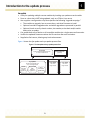
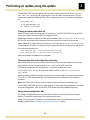
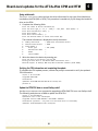
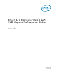
Figure 1 shows the rfw‐update and rsys‐update process flow.
Figure 1. The rfw-update and rsys-update process flow
Linux host
rfw-update
System software upgrade framework
run from an external host
Module 1
rsys-update
reflash
rsys-ipmitool
IPMC
subsystem
upgrade tool
(conf.rfw)
Module 2
Single module upgrade tool
run on the target module
Local LMP
software
upgrade tool
Configuration file
Other
local basic
update utility
9
Module n
rsys-update
rsys-update
run on the
target module
run on the
target module
1
Introduction to the update process
Components supported by rfw-update
ATCA modules typically have a number of firmware and software components that can be updated. These components are programmed into flash devices or logic devices like FPGAs and CPLDs. Some of the devices act as redundant active‐standby pairs that are updated one at a time. Other devices are single, non‐redundant units. The devices in which software and firmware components are stored are referred to as “banks“ in this document.
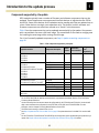
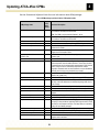
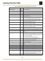
Table 1 lists the components that can be updated automatically by rfw‐update. Components with a second bank can store a fall‐back image. The second bank is also used as a staging area for installing the new image while running the old image. For a list of manually updated components, see Step 9: Update remaining components on page 30.
Table 1. ATCA components supported by rfw-update
Applicable modules
Component description
Number
of banks
Redundant/
Non-redundant
ATCA-1200
ATCA-2210
ATCA-7220
ATCA-9100
ATCA-1200
ATCA-2210
ATCA-4300, ATCA-4310
ATCA-4500, ATCA-4550, ATCA-4555
ATCA-5010
ATCA-5014
ATCA-7220
ATCA-9100
ATCA-4300, ATCA-4310
ATCA-4500, ATCA-4550, ATCA-4555e
Linux and U-Boot image
2
R
Configuration
saved
automatically?
Yesa
IPMC FRU info
IPMC application
IPMC boot block
IPMC FPGA
1
2
1
1
NR
R
R
R
Yes
N/A
N/A
N/A
CPU BIOS
CPU BIOS boot block
DPB FPGAc
DPB boot flashc
SFP+ converter SEEPROM
Boot flash
2
2
1
1
1
1
R
R
NR
NR
NR
NR
Nob
Nob
No
N/A
N/A
N/A
ATCA-7220
AMC-7211
AMC-7212d
a
b
c
d
e
For the ATCA-7220 PPM, the data flow mode selection is not preserved automatically. See the ATCA-7220 Packet
Processing Module Reference.
Use the Linux utility bioscli to save and restore the configuration for the ATCA-4300 and ATCA-4310. Use the bioscli2
utility to save and restore the configuration for the ATCA-4500, ATCA-4550, and ATCA-4555 CPMs. For more
information, see the Compute Processing Module Reference for the CPM.
The DPBs must be running on either U-Boot or Linux.
See Step 6: Update the AMC-7211 and AMC-7212 on page 25 for update instructions for the AMC-7211 and the AMC7212.
For the ATCA-4500, ATCA-4550 and ATCA-4555 CPM, not all components can be upgraded using rfw-update and rsysupdate. See Chapter 6, Board-level updates for the ATCA-45xx CPM and RTM, on page 46 for details.
10
Introduction to the update process
1
Upgrade support policy
This section describes the Radisys general support policy regarding upgrade version compatibilities when upgrading from one ATCA system release version to another. This general support policy outlines which upgrades can be completed without requiring an intermediate step, and which do require an intermediate upgrade step.
Undiscovered defects in previous releases may prevent Radisys from meeting these upgrade objectives. Any deviation from this policy will be noted in the release notes for that release.
Note: In some cases, an example may not refer to a specific Promentum release. Contact Radisys Support for applicable releases for that situation.
Upgrades not requiring an intermediate step
•
•
•
•
•
From the previous minor release
Example: Upgrading ATCA 3.7.0 to ATCA 3.8.0.
From the previous maintenance release
Example: Upgrading ATCA 4.1.1 to ATCA 4.1.2.
From maintenance releases between the previous minor release and the previous maintenance release
Example: Upgrading ATCA 4.1.1 to ATCA 4.1.x.
From the latest maintenance release of the previous major series
Example: Upgrading ATCA 3.x.x to ATCA 4.2.0.
(ATCA 3.x.x is the latest maintenance release for the ATCA 3.x.x series)
From the factory‐programmed versions in place at the time of the software release
Example: Upgrading the current manufacturing programmed version of ATCA 4.0.0 to ATCA 3.8.0.
Upgrades requiring an intermediate step
•
•
From specific older major releases:
• Upgrading ATCA 3.5.0 to ATCA 4.2.0 requires an intermediate upgrade step to the latest 3.x.x maintenance release.
• Upgrading ATCA 3.5.3 to ATCA 4.1.1 requires an intermediate upgrade step to ATCA 4.0.0 first.
From specific older minor releases in the same major series
Example: Upgrading ATCA 4.0.0 to ATCA 4.2.0 requires an intermediate upgrade step to the latest minor release (ATCA 4.1.0).
11
Introduction to the update process
•
•
1
From a maintenance release from an older minor release series
Example: Upgrading ATCA 4.1.1 to ATCA 4.x.x requires an intermediate upgrade step to ATCA 4.2.X first.
From a patch release, which requires an upgrade to the next maintenance release
Example: Upgrading ATCA 4.1.1.3 to ATCA 4.2.0 requires an upgrade to ATCA‐4.1.2 first.
Note: Patch releases are intended to be short‐term releases that are replaced by the next maintenance release.
12
Chapter
2
Performing an update using rfw-update
This chapter describes the use of the rfw‐update remote firmware update utility.
Step 1: Plan the update
Identify the products you want to update
For each Promentum platform, list all installed ATCA modules (except a CPM if it acts as the Linux host for running rfw‐update). For each of the modules, list the slot where it is installed and the connection IP address (for Telnet or SSH access). For example:
Rack #12, Shelf #1: Promentum SYS‐6010
Slot 1: ATCA‐1200; telnet://[email protected]
Slot 2: ATCA‐7220; telnet://[email protected]
Slot 3: ATCA‐7220; telnet://[email protected]
Slot 4: ATCA‐9100; telnet://[email protected]
Slot 5: ATCA‐9100; telnet://[email protected]
To find the IP address of the module to upgrade, log onto the module and enter this command:
ifconfig
Note: The rfw‐update utility ensures that module IP addresses are preserved after a reboot.
13
2
Performing an update using rfw-update
You can print this page and record the module data in this table before running the update:
Slot
Name
IP Address
User:Password
Connection
Type
String
WARNING! Do not include a CPM that is acting as the Linux host for rfw‐update in the list of modules to update. Instead, update the CPM manually before or after updating all other shelf components. See Chapter 3, Using rsys‐update for single product updates, on page 31.
Determine when to perform the update
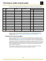
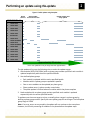
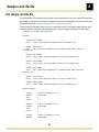
Update planning should take into account the time needed to perform the update and the downtime involved. Figure 2 on page 23 shows an example of the time it took to perform an update after all preparation work was done. In the example—which was optimized to perform many updates in parallel—it took about 90 minutes after the update command was issued to update a fully‐populated ATCA‐6000 12U 14‐slot shelf. The actual time it takes on your system will vary depending on the phases defined in the configuration, networking speed, IPMB traffic, and JFFS access speed.
The firmware and software updates are done on live systems, so downtime is limited to reboots that take approximately 24 minutes for all modules in the shelf. 14
Performing an update using rfw-update
2
Save your configuration
The rfw‐update utility preserves default configurations across updates for the ATCA‐1200, ATCA‐2210, ATCA‐7220, and ATCA‐9100. Configurations are preserved in both banks to retain the existing setup information. Each ATCA software release image contains a list of files to be preserved, and you can generate a custom list to specify additional files within the /etc directory to preserve.
File preservation works as follows:
• Before the OS update begins, the configuration is copied from the active flash bank to the standby flash bank.
• After the update is activated, the module reboots to the standby bank.
• During boot up:
• the saved configuration is saved to a temporary location,
• the directories /rsys/onboot.d and /rsys/onboot.data are removed and repopulated by the new release, and
• the configuration saved in the temporary location is restored to its proper location.
Files preserved by default
File preservation includes various configurations, such as Ethernet (fastpath), module management, shelf management, and others. The system automatically preserves the following files in a default preservation list stored in the /etc/configmgmt.sh file:
/etc/fastpath/fastpath0.cfg
/etc/fastpath/fastpath1.cfg
/etc/fastpath/fastpath.cfg
/etc/snmp/snmpd.conf
/etc/snmp/snmptrapd.conf
/etc/syslog.conf
/etc/ntp.conf
/etc/passwd
/etc/group
/etc/mcli/mclid.cli
/etc/var/lib/snmp/snmpd.conf
/etc/snmp/snmp.conf
/etc/snmp/snmpWatchdog.conf
/etc/snmp/hpiSubagent.conf
/etc/shmgr.conf
/var/lib/shmgr/ShelfFruCopy.bin
/var/lib/shmgr/hcf.tgz
/root/.snmp/snmp.conf
/etc/shmgralarm.conf
/etc/fruinfo.conf
/var/lib/shmgr/atca‐6002.bin
15
Performing an update using rfw-update
2
For the ATCA‐7220, the rsys‐update utility creates a custom preservation list at /etc/rsys‐
user‐file‐list.cfg during the update process if the file does not already exist. The rsys‐
update utility adds the following ATCA‐7220 configuration files to that custom preservation list:
/etc/octeon.conf
/etc/fpga/ppm20fpga.conf
All files in /etc/octeon
Creating a custom preservation list
Other files may need to be preserved. For example, on an ATCA‐2210 SCM running a DHCP server, you might preserve the DHCP configuration files.
Additional preserved configuration files must be added to the /etc/rsys‐user‐file‐list.cfg file. This file may need to be created the first time custom files need to be preserved.
When adding files, make sure each file name is on its own line in rsys‐user‐file‐list.cfg and includes the full path. For example, these commands add the xxx.cfg and yyy.cfg files to the custom preservation list:
echo "/etc/xxx.cfg" > /etc/rsys‐user‐file‐list.cfg
echo "/etc/yyy.cfg" >> /etc/rsys‐user‐file‐list.cfg
Save the file when the additions are complete.
Preserving other files and configurations manually
Most files outside of /etc cannot be preserved by the tools. Consider whether to manually save the files you have created outside of /etc, such as the DHCP leases file.
To preserve configuration files outside the /etc directory, add them to the /rsys/onboot.data/overlay directory and reference them in the /etc/rsys‐user‐file‐
list.cfg file.
An alternative method for manually saving files is to copy the files to a remote server (using FTP, SFTP, or TFTP) before updating. Copy them back to the module after the update is complete.
Note: Use FTP or SFTP to achieve the best performance and reduce the update time.
For the ATCA‐7220 PPM, data flow mode selection is not preserved automatically. For details on mode configuration, refer to the ATCA‐7220 Packet Processing Module Reference.
Saving custom configuration data
Any custom configuration data must be explicitly saved or it will be lost when a module reboots. The default preservation list is automatically saved.
Before continuing with a firmware or software update, save any custom preservation list changes as described in Creating a custom preservation list, above.
16
Performing an update using rfw-update
2
Determine which modules require an IPMC FPGA update
IPMC FPGA devices should be updated separately using rsys‐update before running rfw‐
update to automatically update the other module components. This separate update is required so the rfw‐update process runs without interruption and does not require manual user intervention.
The IPMC FPGA update is required only if the installed version of the IPMC FPGA differs from the version provided with the latest software release. Follow these steps to determine which modules require IPMC FPGA updates:
1. Check the IPMC FPGA version on each system module by running the following command on the ATCA‐2210 LMP command line:
rsys‐ipmitool ‐t <module IPMB address> hpm check
See Table 6 on page 86 for the IPMB addresses of all IPMCs in the system.
2. Determine the current version of the IPMC FPGA firmware. This information is listed in the product revision levels table of the current Promentum software release notes. The release notes are available on the Promentum software product media.
See Step 4: Update IPMC FPGA devices on page 20 for IPMC FPGA update instructions.
Step 2: Obtain the update bundles from Radisys
The latest Promentum software image may be available at www.Radisys.com/downloads. Browse to the Promentum SYS‐6014/SYS‐6016 downloads page and download the Promentum software release ZIP file from the Software downloads section. Extract the ISO image and optionally create a DVD containing the module update bundles. Contact Radisys Support for the Promentum image if the latest version is not available on the Radisys web site.
For each module supported by rfw‐update, the image contains:
• An update bundle ending in firmware.tgz. The update bundle package is optimized for the rsys‐update and rfw‐update tools. The package should only be used when upgrading using rsys‐update and rfw‐update. The update bundle also contains the latest version of the rsys‐update and rfw‐update utilities, as well as scripts to perform the update. Multiple update bundles are provided when multiple operating systems are supported. • A user bundle ending in <version>.tgz. This file is a package containing the tools, supporting applications, source files, and documentation needed for development. The user bundle .tgz file is usually of significant size.
Note: The firmware updates for the ATCA‐5010 and the ATCA‐5014 SPMs are included in the ATCA‐2210 firmware update bundle. 17
Performing an update using rfw-update
2
Step 3: Prepare the Linux host
Prerequisites
The host system that runs rfw‐update must be a Linux host with LAN access to the modules installed in the shelf. The host system must be running Perl version 5.8.5, and specific Linux, Radisys, and Perl RPMs must also be installed. See Getting required packages for the list of required RPMs. All update targets must be accessible from the host running rfw‐update. An ATCA‐4500 CPM in the shelf to be upgraded can be used for this purpose.
Radisys has validated rfw‐update on a Dell™ PowerEdge™ 1U server running Red Hat® Enterprise Linux 4. The rfw‐update utility is also supported on Wind River Platform for Network Equipment, Linux Edition, version 1.4, and on Monta Vista® Linux, Carrier Grade Edition 5.
Getting required packages
Preparing the host requires installing Linux RPM packages from the Promentum image. You can find the RPMs by decompressing the CPM file ending in <version>.tgz. The RPMs for each supported OS are located under the packages directory. See Preparing the host system on page 18 for details on decompressing the <version>.tgz file.
This Radisys RPM is required for use of the rfw‐update utility:
• rfw‐update‐<version>.noarch.rpm
These Perl RPMs are also needed by rfw‐update:
• perl‐YAML
• perl‐Expect
• perl‐IO‐Tty
• perl‐Net‐Telnet
• perl‐Inline
Preparing the host system
1. Verify that Perl is installed on the host system by entering:
perl ‐v
Notes:
• If Perl is not installed on your system, install it according to your vendor instructions.
• If the version of Perl you are using is not 5.8.5, enter the following command:
export PERL5LIB=/usr/lib/perl5/5.8.0/:$PERL5LIB
The export command assigns the path /usr/lib/perl5/5.8.0 to the PERL5LIB environment variable. The rfw‐update utility places Perl modules in the /usr/lib/perl5/5.8.0/ directory, so configuring PERL5LIB helps rfw‐update find the modules. 18
Performing an update using rfw-update
2
2. Install the latest RPM packages.
a. Locate the <version>.tgz file appropriate for your operating system in the Promentum CD image, as explained in Getting required packages on page 18. Copy the <version>.tgz file to a temporary directory on the Linux host. Choose a path and name that can be easily accessed for the remaining steps.
b. Decompress the <version>.tgz file by entering the following command from within the temporary directory:
tar ‐xzvf <version>.tgz
This creates a directory named <version> in the temporary directory.
c. Install or update the Perl RPMs by entering:
rpm ‐Uhv <path_to_packages>/perl‐*
The system will announce if any RPMs are already installed.
3. Install the rfw‐update RPM package appropriate for your host from the Promentum software image. Locate, copy, and install the rfw‐update RPM in a similar way to the Perl RPMs in Step 2.
rpm ‐Uhv <path_to_packages>/rfw‐update‐*
4. (Optional) When using a CPM as the host, manually update the firmware and BIOS images on the host using rsys‐update. For more information, see Chapter 3, Using rsys‐update for single product updates, on page 31.
19
Performing an update using rfw-update
2
Step 4: Update IPMC FPGA devices
IPMC FPGA devices for modules must be updated separately using rsys‐update before running rfw‐update to automatically update the other module devices. Refer to the product release notes to identify any IPMC FPGA updates.
Follow these steps to perform the update:
1. Determine which modules require IPMC FPGA updates by comparing their installed IPMC FPGA version with the latest Promentum software release. See Determine which modules require an IPMC FPGA update on page 17 for details.
2. Run rsys‐update on each module that requires an IPMC FPGA update, specifying the path to the firmware update bundle. The following command updates the module’s IPMC FPGA and associated IPMI firmware:
rsys‐update ‐‐path <xxx‐firmware.tgz> ‐‐ipmi‐firmware:update
Note: See rsys‐update command options on page 32 for details about the rsys‐update command options used in this document.
To update the IPMC FPGA for the ATCA‐5010 or ATCA‐5014 SPM, run the following command from the ATCA‐2210 and specify the IPMB target address (0xE4 for the SPM in slot 7, or 0xE6 for the SPM in slot 8):
rsys‐update ‐‐path <xxx‐firmware.tgz> ‐‐ipmi‐firmware:update ‐‐ipmb‐target
<IPMB target address>
3. Activate the updated component:
rsys‐update ‐‐path <xxx‐firmware.tgz> ‐‐ipmi‐firmware:activate
Similarly, activate the updated component for the ATCA‐5010 or ATCA‐5014 SPM:
rsys‐update ‐‐path <xxx‐firmware.tgz> ‐‐ipmi‐firmware:activate ‐‐ipmb‐target
<IPMB target address>
4. Remove and reinsert the module.
Note: If the module power‐cycles then it does not need to be removed. Some modules with release 3.5.0 or greater Promentum software will power cycle automatically, so removal and reinsertion is not required.
See Appendix C, Power cycling after IPMC FPGA upgrades, on page 88 for details about the modules that may require a manual power cycle.
See Chapter 3, Using rsys‐update for single product updates, on page 31 for additional information about using rsys‐update for individual updates.
20
2
Performing an update using rfw-update
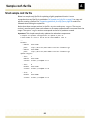
Step 5: Create a configuration file (conf.rfw)
The rfw‐update utility uses a configuration text file to specify which modules should be updated and whether they will be updated in parallel with other modules to save time. The text file can be any name, but it is named conf.rfw in this document.
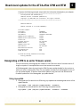
The conf.rfw file contains a list of bundles with URL paths and a list of update targets with Telnet connect strings. The update target connect string contains the IP address and, if needed, login information to allow a connection from the host to the update target. All update targets must be accessible from the host running rfw‐update.
The conf.rfw configuration file also identifies the locations of the update bundles. The bundles in the conf.rfw file must contain valid URL paths from each target to update bundles somewhere on the system (not necessarily on the host).
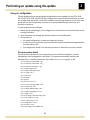
The bundles do not need to be in the same location where rfw‐update is run with conf.rfw, but the bundles must be accessible from the update target using the specified URL. The IP connections are shown in the following diagram:
Host running rfw-update
Target
module
tftp/ftp/www server
containing update bundle
IP address
(example: 10.10.10.1)
IP address
(example:
10.10.10.2)
WARNING! Do not include a CPM that is acting as the Linux host for rfw‐update in the conf.rfw configuration file. Including the host as an update target would interrupt the update process for the CPM and potentially for other modules in the shelf. Instead, update the CPM manually using rsys‐update either before or after updating all other shelf components. See Chapter 3, Using rsys‐update for single product updates, on page 31.
The conf.rfw file can be set up to run the update process on modules sequentially or in parallel. When modules are updated in parallel, they are in the same phase group. See Set up phase groups on page 22.
Run man rfw‐update for complete information.
Create conf.rfw from example.rfw
You can generate conf.rfw from the example.rfw text file that is available in /usr/share/rfw‐
update/ after the rfw‐update installation. The file is correctly formatted and contains most of the keys, so edit it as needed and save the file as conf.rfw.
21
Performing an update using rfw-update
2
Create conf.rfw from samples in the appendix
The conf.rfw file can also be created by referring to samples documented in Appendix A, Sample conf.rfw file, on page 78. A simple example is provided for reference and general use, and the detailed example can be used to produce a complete module update list.
Compose and verify the configuration file
1. Use a text editor to create a configuration file. Refer to Appendix A, Sample conf.rfw file, on page 78 for a template. See Configuration file syntax on page 78 for file setup details.
2. Save the configuration file as conf.rfw to an easily accessible directory and in a location that can be accessed by the Linux host system where rfw‐update will execute.
3. Use the following commands to verify the format and test the structure and syntax of conf.rfw, the connections to each module and bundle, and versions of both.
To see an overview of the update order as you develop the conf.rfw file:
rfw‐update ‐‐parse‐only <path_to_conf.rfw>/conf.rfw
Verify the syntax of the configuration file and test the connections to each module:
rfw‐update ‐‐quick‐check <path_to_conf.rfw>/conf.rfw
Verify that each target can access the bundles from the module. This command shows the versions of all bundles and modules:
rfw‐update ‐‐versions <path_to_conf.rfw>/conf.rfw
Set up phase groups
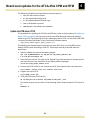
The conf.rfw file can be set up to run the update process on modules sequentially or in parallel. When modules are updated in parallel, they are in the same phase group. A parallel update is shown in Figure 2 on page 23. The gray bars in the diagram show how rfw‐update performs operations on the node modules simultaneously in different stages of the update process. You can place any update target into a specific phase group using the phase option in conf.rfw. If a phase group is not specified for the update target, the target is placed in its own unique phase group and the target is updated sequentially. WARNING! Place any module that provides network connectivity to other modules in its own phase group. Otherwise, when the module is rebooted, the update process for the other modules may be disrupted.
You can see an overview of the update order as you develop the conf.rfw file with the ‐‐
parse‐only option. For example:
rfw‐update ‐‐parse‐only conf.rfw
22
2
Performing an update using rfw-update
Figure 2. Parallel updates using rfw-update
Quick
connect
Update module and
verify update
Verify bundle
access and version
SYS-6010 Shelf
1.
ATCA-9100
2.
ATCA-4500
3.
ATCA-4500
4.
ATCA-9100
5.
ATCA-7220
6.
ATCA-9100
7.
ATCA-2210
ATCA-5010/5014
8.
ATCA-2210
ATCA-5010/5014
9.
ATCA-4500
10.
ATCA-4500
11.
ATCA-9100
12.
ATCA-7220
13.
ATCA-9100
14.
ATCA-7220
Approximately 90 minutes
Note: Your update time may be longer than this approximation.
The rfw‐update utility uses the following rules to order the update targets:
1. Hub modules (ATCA‐2210 SCMs) with no phase group number specified: each module is updated sequentially with the entire specified bundle.
2. User‐defined phase groups:
• Each module is updated with the entire specified bundle
• Modules within a phase group are updated in parallel
• One or more modules can be updated per phase group
• Phase updates occur in phase number sorted order
• The phase update is finished when all modules within the phase complete
3. Node modules with no phase group number specified: each module is updated sequentially with the entire specified bundle.
To update more than one target at a time, manually place a target in a phase group by defining a phase group number. Specify the same phase group for each target. The valid phase group range is 0–999.
Note: If an error occurs on any module, the update will not continue to the next phase. However, it will finish processing all modules in the phase before the update stops.
23
Performing an update using rfw-update
2
Selecting the update order
The order that modules and components are updated is determined by a number of setups.
• The update order is controlled in the conf.rfw file to establish phase groups.
• The rfw‐update utility uses its own rules to order multiple modules within the phase groups (see Set up phase groups on page 22 for details).
• The update order may also be controlled by configuring multiple rfw‐update files to run sequentially. This allows manual updates to occur between steps, if necessary.
When you select an update order, the following constraints should be kept in mind:
• Place a module that provides network connectivity to other modules in its own phase group. The update process for other modules may be disrupted when the module reboots.
• The default setting is to update both banks of redundant components. See Updating both banks about this default setting and how to set up conf.rfw to update a single bank.
To update the AMC‐7211 and AMC‐7212, you must apply manual update operations between rfw‐update executions, as described in Step 6: Update the AMC‐7211 and AMC‐7212 on page 25.
Updating both banks
Some updatable components are redundant, which means they have two banks containing separate firmware loads. By default, the rfw‐update utility automatically updates both banks to the same firmware using the image in the bundle.
To update a single bank of a redundant component, specify update‐banks:single in the configuration file. See Configuration file syntax on page 78 for details.
If the update‐banks:single option is used, see the set‐bank option to specify which boot bank is active during the update. The rfw‐update utility updates the non‐active bank. For example, if set‐bank:0 is specified then bank 1 is updated.
24
Performing an update using rfw-update
2
Step 6: Update the AMC-7211 and AMC-7212
The AMC‐7211 and AMC‐7212 are updated as a non‐redundant component as part of the ATCA‐1200 update bundle, or from a CPM host. While the AMC flash is a non‐redundant component, the host support, which is updated at the same time, is not because it resides in the redundant LMP. Consequently, the host support is only updated in the active LMP and not in the redundant LMP.
WARNING! The support for the AMC‐7211 and AMC‐7212 must be installed and operational on the CPM or ATCA‐1200 before you can update the AMCs. For driver installation details, see the Installing software on the carrier section in the Installation Procedure Supplement chapter of the Promentum Quad Gigabit Ethernet AMC Reference for the AMC‐7211 and AMC‐7212.
Update the LMP and AMC host support
Follow these steps to update the LMP and AMC host support in both AMC flash banks. In this procedure, bank 0 is the currently active bank and bank 1 is the redundant bank.
1. Run rsys‐update ‐‐redundant to update bank 1. The system automatically reboots to bank 1. rsys‐update ‐‐path /<tmp‐dir>/<update‐bundle> ‐‐automatic ‐‐redundant
Note: See rsys‐update command options on page 32 for details about the rsys‐update command options used in this document.
2. Manually install the Cavium host support software. The Cavium processors reboot after the host support software is installed. For installation instructions, see the Updating the software section in the Quad Gigabit Ethernet AMC Reference for AMC‐7211 and AMC‐
7212.
3. Run rsys‐update ‐‐redundant to update bank 0. The system automatically reboots to bank 0.
rsys‐update ‐‐path /<tmp‐dir>/<update‐bundle> ‐‐automatic ‐‐redundant
4. Manually install the Cavium host support software.
5. Run rsys‐update ‐‐non‐redundant to update the AMC‐7211 or AMC‐7212 Caviums again. Now the new active bank (bank 0) is updated with the new Cavium host support.
rsys‐update ‐‐path /<tmp‐dir>/<update‐bundle> ‐‐automatic ‐‐non‐redundant
Update the IPMI firmware and FRU data
See Chapter 8, Updating IPMI FW and FRU data for an AMC or RTM, on page 72 for details about updating the AMC IPMI firmware and FRU data.
25
Performing an update using rfw-update
2
Step 7: Run the rfw-update utility
Quick start
Follow these steps to verify the system configuration file and update bundles, then run rfw‐
update to automatically update the modules.
Important: You must have root account access for rfw‐update to operate properly.
1. Verify the syntax of the configuration file and test connections to each module:
rfw‐update ‐‐quick‐check conf.rfw
2. Verify that each target can access the bundles from the module. Use this command to show the versions of all bundles and modules:
rfw‐update ‐‐versions conf.rfw
3. Enter this command to start the update process:
rfw‐update –‐automatic conf.rfw
rfw-update command details
Syntax
rfw‐update {tasks} <FILE>
Note: At least one of the following tasks must be specified when rfw‐update is invoked.
{tasks}
‐a, ‐‐automatic
Performs an automatic update.
‐p, ‐‐parse‐only
Reads and verifies the configuration file and displays an overview of the update order.
‐q, ‐‐quick‐check
Quickly connects to the module and performs simple checks to see if it is ready.
‐s, ‐‐show‐tool‐version
Shows tool version information and exits.
‐v, ‐‐versions
Shows version information of all active, standby, and update bundle components, then exits.
<FILE>
The configuration file (called conf.rfw in this document) can have any name and is the chassis or network description file for the system.
For more detailed help and syntax for the conf.rfw file, enter the following command:
rfw‐update ‐‐man <path to conf.rfw>/conf.rfw
26
Performing an update using rfw-update
2
Examples
rfw‐update ‐‐parse‐only conf.rfw
Verifies the syntax of a bundle configuration file and shows an overview of the update order.
rfw‐update ‐‐quick‐check conf.rfw
Verifies the syntax of a bundle configuration file and connects to each target.
rfw‐update ‐‐versions conf.rfw
Shows the version information for all bundles and modules defined in the conf.rfw file.
rfw‐update ‐‐automatic conf.rfw
Updates all modules using the bundles and targets defined in the conf.rfw file.
Update process
Assumptions
The rfw‐update utility assumes the following:
1. Prior to the update, all modules are in a stable state.
2. Prior to the update, all modules have saved their running configurations.
3. All update targets are reachable from the host machine running rfw‐update.
4. All bundles are reachable from the update target for download.
5. All modules, during and after their update, remain reachable from the host machine running rfw‐update.
Update passes
The update of each module consists of three passes.
Note: The update process stops and must be restarted if a failure occurs during any step.
1. Quick Module Check Pass can be run with the ‐‐quick‐check option.
• Connect to the module
• Verify rsys‐update is not running
• If specified, verify the slot is correct
• If specified, verify the chassis is correct
2. Verify Module Pass can be run using the ‐‐versions option.
• Runs Quick Check Pass
• Download the specified bundle
• Run a version check
• If specified, check to make sure the module is in the expected bank
• If specified, boot the module to the expected bank
27
Performing an update using rfw-update
2
3. Update Module Pass can be run using the ‐‐automatic option.
• Runs Quick Check Pass
• Runs Verify Module Pass
• Saves the configuration to the standby bank
• Updates the firmware from the specified bundle to the standby bank
• Reboots to the standby bank
• After reboot, verifies the update was good
• If specified, runs a user‐provided post‐update script
•
•
•
•
•
By default, it runs an update on the standby bank and reboots the module
Saves the configuration to the standby bank
Updates the firmware from the specified bundle to the standby bank
Reboots to the standby bank
After reboot, verifies the update was good
If specified, runs a user‐provided post‐update script
Log files
Update messages are saved to ./log/*.log unless another directory is specified with the ‐‐log‐dir option on the command line.
28
Performing an update using rfw-update
2
Step 8: Rediscover the shelf
Log in to the ATCA‐2210 SCM that is hosting the active Shelf Manager. Access the CLI and enter:
platform‐mgmt
rediscoverShelf
This ensures that the HPI RPT information is in sync with new versions running in the system.
Recovering from update problems
If you encounter problems with an update, you can usually recover by updating the component from the redundant bank. Use rsys‐update or component update tools from the working bank.
If Linux or U‐Boot is corrupted on the ATCA‐1200, ATCA‐2210, ATCA‐7220 or ATCA‐9100, see the Promentum Software Guide for recovery instructions.
If the CPM BIOS is corrupted in both banks, see the CPM BIOS Crisis Recovery Instructions for the specific CPM.
Note: Repeat the update process for redundant programmable devices in order to flash the second bank. This second update is required for the CPMs because the redundant BIOS feature requires both BIOS banks to be at the same version.
Restoring older firmware or software
To downgrade to a previous version of firmware or software, see Chapter 9, Installing previous firmware or software versions, on page 76. Refer to the documentation for the version to which you are downgrading as well.
See the product revision levels table in the Promentum software release notes for component version compatibility. The software release notes are available on the latest Promentum software product media.
29
Performing an update using rfw-update
2
Step 9: Update remaining components
The following products and components are either not supported by rfw‐update and their updates must be handled separately, or some updates need to be performed manually along with rfw‐update. Instructions for updating these products and components are included with the individual component update files, unless otherwise indicated.
For an explanation of the update files provided, see Step 2: Obtain the update bundles from Radisys on page 17.
• CE3100 COM Express module (ATCA‐2210 option).
• Advanced Mezzanine Cards: AMC‐3201, AMC‐3202, and AMC‐3203 Hard Drive Storage Modules. See Chapter 8, Updating IPMI FW and FRU data for an AMC or RTM, on page 72 for AMC update information.
• ATCA‐1200 RTM. For details, see the Installing software on the carrier section in the Installation Procedure Supplement chapter of the Promentum Quad Gigabit Ethernet AMC Reference for the AMC‐7211 and AMC‐7212. See Chapter 8, Updating IPMI FW and FRU data for an AMC or RTM, on page 72 for IPMI firmware and FRU data update procedures.
• ATCA‐1200 custom drivers and utilities for AMCs, such as the AMC‐7211 and AMC‐7212 host support package. Reinstall the package as described in the Installation Procedure Supplement chapter of the Quad Gigabit Ethernet AMC Reference.
• AMC‐7211 and AMC‐7212 IPMI firmware. For details, see Chapter 8, Updating IPMI FW and FRU data for an AMC or RTM, on page 72.
• A CPM if it is used as the host that runs rfw‐update. The rfw‐update utility must not be configured to update the host on which it is running. The CPM firmware and BIOS can be updated using rsys‐update before or after using rfw‐update. If not done previously, update the CPM as described in Chapter 3, Using rsys‐update for single product updates, on page 31.
• Linux RPM packages provided by Radisys for the CPMs. Refer to Step 3: Prepare the Linux host on page 18 for RPM installation instructions. Update the RPMs before running rsys‐
update on the module, as described in Step 3: Prepare the Linux host on page 18.
• RCM (Radisys Chassis Manager) for the ATCA‐6014 and ATCA‐6016 shelves.
• FRU data for the Promentum shelves. See Chapter 7, Updating and customizing FRU data, on page 68.
• PEM and FAN firmware for the ATCA‐6006 shelf. Refer to the readme files on the Promentum software image.
30
Chapter
3
Using rsys-update for single product updates
This chapter describes the rsys‐update utility, with which you can update most components in a single ATCA module with one command. (See note below.) Use rsys‐update to update a module that is not updated by rfw‐update, such as a CPM that acts as the host for running rfw‐update. Table 1 on page 10 lists the components updated by rfw‐update, which invokes multiple instances of rsys‐update during the upgrade process.
Note: The rsys‐update utility is not used to update the ATCA‐4580 CPM. See Chapter 6, Board‐
level updates for the ATCA‐45xx CPM and RTM, on page 46 for ATCA‐4580 update procedures.
Modules running ATCA software (ATCA‐1200/2210/7220/9100) have the rsys‐update utility installed in the /usr/sbin directory of the module. This allows rsys‐update to start the update process using scripts contained within the update bundle.
Important: Update the RPMs on all modules before running the rsys‐update utility.
31
Using rsys-update for single product updates
3
rsys-update command options
Table 2 on page 32 describes the rsys‐update command options that are used in these update instructions.
Table 2. Command options for rsys-update
Option
Parameters
‐a, ‐‐automatic
Description
Update and activate firmware in the factory recommended order (update the redundant
components).
‐v, ‐‐versions
Show version information for all active, standby, and update bundle components.
‐‐path <update‐bundle> The URL, full path or directory path to the update bundle.
‐‐redundant
Update only the redundant components (components with more than one bank)
‐‐non‐redundant
Update only the non-redundant components (components with a single bank)
‐‐both
Update both the redundant and non-redundant components.
Component actions
‐‐<component>:update
Update the component. The standby component is updated if there is a redundant pair.
Example: --ipmi-firmware:update
‐‐<component>:activate Activate the updated component.
‐‐<component>:versions Display the versions of the components.
Qualifiers
‐d, ‐‐dry‐run
Output the steps that the update would run
‐e, ‐‐erase‐jffs
When updating the system-os component, erase the JFFS2 file system as part of the
update operation.
‐p, ‐‐primary
Update the primary flash bank when performing the system-os update.
‐s, ‐‐secondary
Update the secondary flash bank when performing the system-os update.
‐m, ‐‐ipmb‐host IPMB address of the host module. The default is derived using fruinfo.
<IPMB host address>
‐t, ‐‐ipmb‐target IPMB address of the target module to update. The default is --ipmb-host.
<IPMB target address>
32
Using rsys-update for single product updates
3
rsys-update help
Two forms of help are available for rsys‐update if an update bundle is specified in the help command. Use the help commands to view the rsys‐update command syntax.
Help on retrieving the update bundle
When the rsys‐update help command is entered without specifying an update bundle, the utility only gives help on how it can be used to retrieve an update bundle. To obtain this help information, enter this command at the Linux shell:
rsys‐update ‐‐help
Help on updating the ATCA module
More detailed help is available when the update bundle is present and specified in the help command because the bundle contents provide information about which components can be updated. The help also includes information on how to update the firmware and software components on the ATCA module. Enter this command at the Linux shell: rsys‐update ‐‐help ‐‐path <update‐bundle>
Using URLs with rsys-update
The supported URL protocols are SFTP and TFTP. If the wget utility is installed on the module, FTP, HTTP, and HTTPS are also supported.
Note: Use FTP or SFTP to achieve the best performance and reduce the update time.
When a URL is specified, the update bundle is downloaded to the module at /<tmp‐
dir>/<update‐bundle>.tgz. The tarball is extracted into the directory /<tmp‐dir>/<update‐
bundle>/. The URL format specifies the method used to copy the bundle from the host to the module:
rsys‐update ‐‐path sftp://<username>@<hostip>/<update‐bundle>.tgz
rsys‐update ‐‐path tftp://<hostip>/<update‐bundle>.tgz
The URL beginning with “sftp” uses SSH for data transfer, and uses the same authentication and provides the same security as SSH. The process prompts you for passwords or pass phrases if they are needed for authentication. The file name may contain a host and user specification to indicate the file is to be copied from that host. The rsys‐update utility assumes that SSH is available on the remote host.
The URL beginning with “tftp” uses TFTP for data transfer. The rsys‐update utility assumes that a TFTP server is accessible from the module and the update bundle is in the /tftpboot directory. Note: If problems occur with the TFTP data transfer, make sure the TFTP server is accessible from the module. Do this by attempting to connect to the TFTP server using the TFTP utility from the Linux shell. For best performance, use either FTP or SFTP.
33
Using rsys-update for single product updates
3
Using full path lists
If a full path is specified and the tarball file with a file name ending in “.tgz” exists, the tarball bundle contents are extracted into the directory /<tmp‐dir>/<update‐bundle>. The format of the full path is:
/<tmp‐dir>/rsys‐update/<update‐bundle>.tgz
Using local directories
If a directory is used and the update command exists in the update‐bundle directory, the directory is used as‐is and no file is extracted. The format of the command is:
/<tmp‐dir>/<update‐bundle>
Updating all redundant components on a single module
This procedure updates all redundant components on a single module (see Table 1 on page 10). After completing this procedure, proceed to Updating non‐redundant devices on page 35.
Notes:
• For IPMC FPGA device updates, see Step 4: Update IPMC FPGA devices on page 20 for specific procedures and commands.
• Using rsys‐update to perform a software downgrade for the ATCA‐2210 may successfully update bank 1 for the FPGA firmware, but the bank 2 update may fail and display the error Error uploading firmware block.
The error may occur because the IPMC firmware prevents the FPGA downgrade process, since the module could be rendered inoperable. You can ignore this FPGA‐related rsys‐
update error if you perform a software version downgrade on an ATCA‐2210.
• Some CPMs require a jumper setting before the BIOS boot block can be updated. See Chapter 5, Setting the CPM boot block jumpers, on page 43.
To update a module’s redundant components:
1. Log in to the module.
2. Check the active and standby flash bank versions to confirm your decision to update:
rsys‐update ‐‐path /<tmp‐dir>/<update‐bundle> ‐‐versions
Note: Throughout these steps, to point to an uncompressed update bundle specify the ‐‐
path option to the “.tgz” file instead. For example: ‐‐path /<tmp‐dir>/rsys‐update/<update‐bundle>.tgz
3. Make sure the module is in the intended bank by using the ‐‐dry‐run option of rsys‐
update. This command displays a simulation of the update procedure, and identifies the current active bank and the targeted update bank. rsys‐update ‐‐path /<tmp‐dir>/<update‐bundle> ‐‐secondary ‐‐dry‐run ‐‐automatic
34
3
Using rsys-update for single product updates
4. Update the standby flash bank:
rsys‐update ‐‐path /<tmp‐dir>/<update‐bundle> ‐‐automatic
This results in a reboot to the standby (newly updated) flash bank.
5. For local management processor (LMP) modules, confirm the new version works correctly:
flashver ‐‐secondary
6. Download the update bundle again, since the temporary storage was lost upon reboot. Refer to the previous section for detailed instructions.
7. Flash the remaining (original active) flash bank.
rsys‐update ‐‐path /<tmp‐dir>/<update‐bundle> ‐‐automatic
This results in a reboot to the original active (now updated) flash bank.
8. Repeat the update process for redundant programmable devices in order to flash the second bank. This second update is required for the ATCA‐43xx because the redundant BIOS feature requires both BIOS banks to be at the same version.
Updating non-redundant devices
Run the rsys‐update utility again and specify the ‐‐non‐redundant option to update any non‐
redundant devices. Examples include:
• Board IPMC FRU data (ATCA‐4300, ATCA‐4310, ATCA‐4500, ATCA‐4550, ATCA‐4555, ATCA‐
1200, ATCA‐2210, ATCA‐7220, ATCA‐9100)
• ATCA‐7220 DPB FPGA and software
• AMC‐7211 and AMC‐7212 boot flash
See Table 1 on page 10 for a full listing of redundant and non‐redundant devices for each product.
To update a module’s non‐redundant devices:
1. Use the dry‐run option of rsys‐update. This command displays a simulation of the update procedure and identifies the targeted non‐redundant devices. rsys‐update ‐‐path /<tmp‐dir>/<update‐bundle> ‐‐dry‐run ‐‐automatic redundant
‐‐non‐
2. Update the non‐redundant devices:
rsys‐update ‐‐path /<tmp‐dir>/<update‐bundle> ‐‐automatic ‐‐non‐redundant
For example, the following command updates the device using the factory recommended order and outputs a log file if any errors occur:
rsys‐update ‐‐path /tmp/rsys‐update/ATCA‐4300‐2.3.13‐2‐rh‐firmware/ automatic ‐‐non‐redundant ‐‐log‐file logfile
‐‐
3. After the reboot, enter this command to confirm the new version:
rsys‐update ‐‐path /<tmp‐dir>/<update‐bundle> ‐‐versions ‐‐non‐redundant
35
Using rsys-update for single product updates
3
Updating the ATCA-7220 DPB BSPs from 1.4.x to 1.5.x
To update the ATCA‐7220 DPB from 1.4.x to 1.5.x (SDK 1.7.2 to 1.9), different update procedures are used if the DPB is booted to Linux or to U‐Boot.
Booted to Linux
If the ATCA‐7220 DPB is booted to Linux, the DPB BSP can be updated using the following command:
rsys‐update ‐‐path ATCA‐7220‐1.12.14.1.4_SDK1.9_Octeon1.5‐1‐firmware.tgz automatic ‐‐non‐redundant
‐‐
Booted to U-Boot
The DPB BSP flash mapping is modified for the 1.5.x update, so the ‐‐automatic ‐‐non‐
redundant options cannot complete the update if the DPB is booted to U‐Boot. Instead, execute the following command to update all flash memory from 1.4.x to 1.5.x and ignore the flash map check:
rsys‐update ‐‐path ATCA‐7220‐1.12.14.1.4_SDK1.9_Octeon1.5‐1‐firmware.tgz DPB‐os:update ‐‐override ‐‐all
36
‐‐
Chapter
4
Updating ATCA-45xx CPMs
This chapter describes the installation of RPM packages and the BIOS driver for updating ATCA‐4500, ATCA‐4550, ATCA‐4555, and ATCA‐4580 CPMs.
These are the operating systems supported by the ATCA‐4500, ATCA‐4550, and ATCA‐4555 CPMs:
• Monta Vista 4, 32‐bit (Monta Vista CGE 4.0 i386)
• Monta Vista 5, 64‐bit (Monta Vista CGE 5.0 x86‐64)
• Red Hat 5, 64‐bit (Red Hat 5.4 x86_64)
• Wind River 2, 32‐bit (Wind River PNE‐LE 2.0 i686)
• Wind River 2, 64‐bit (Wind River PNE‐LE 2.0 x86_64)
These are the operating systems supported by the ATCA‐4580 CPM:
• Red Hat 5.4, 64‐bit
• Wind River 3.0, 64‐bit
Each operating system has its own set of RPM packages that need to be installed to support automated updates using rfw‐update and rsys‐update, or manual board‐level updates using the individual update tools. For board‐level component updates, the update procedure notes which RPM packages are required for that update.
Contact Radisys Support if additional assistance is needed for installing the required RPM packages for specific operating systems.
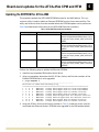
Installing the required OS RPM packages
Before running the update, you need to prepare the CPM by installing the latest OS RPMs. Locate the RPMs by decompressing the ATCA‐4500‐<version>.tgz, ATCA‐4550‐<version>.tgz, or ATCA‐4555‐<version>.tgz file for your specific OS. The file is located in the ATCA‐4500, ATCA‐4550, or ATCA‐4555 directory on the software release image. The RPMs are in the RPMS folder within the packages folder.
Table 3 on page 38 lists the Radisys RPM packages for the CPM, and provides a brief functional description of their contents. The Required for the update process column indicates which RPM packages should be installed to support both automated and manual update methods.
Note: Depending on your OS type or version, some of the RPMs listed are not supplied.
37
4
Updating ATCA-45xx CPMs
See the Promentum Software Guide for more information about RPM packages.
Table 3. RPM packages provided with the CPM update bundle
RPM package name
AMC7212.RH.4500-<version>.rpm
Required
for the
Functional description
update
process
No
Provides libraries, utilities, and PCIe drivers for the AMC-7212 on the
ATCA-4500, ATCA-4550, and ATCA-4555.
amifldrv-<version>.rpm
Yes
amifldrv-core8-<version>.rpm
bioscli2-<version>.rpm
biosver-<version>.rpm
Yes
No
Yes
cpm_ioport_module-<version>.rpm
Yes
cpm_ioport_module-link<version>.rpm
cpm-release-<version>.rpm
cpm-utils-<version>.rpm
Yes
No
No
fruinfo-<version>.rpm
Yes
fru-update-<version>.rpm
garp-<version>.rpm
Yes
No
igb-<version>.rpm
ispVMEmbedded-<version>.rpm
ixgbe-<version>.rpm
No
Yes
No
libhcl-<version>.rpm
libhcl-devel-<version>.rpm
libmpf-<version>.rpm
No
No
No
libmpf-devel-<version>.rpm
libmpf-link-<version>.rpm
libsml-<version>.rpm
libsml-devel-<version>.rpm
No
No
No
No
Note: This RPM is only required for Red Hat 5, 64-bit.
A kernel driver module that is required for updating the BIOS for the
ATCA-4500, ATCA-4550, and ATCA-4555.
A kernel driver module required to update the ATCA-4580 BIOS.
A command-line interface for manipulating EFI BIOS options in Linux.
A tool that displays the BIOS version and BIOS image file version
number for the module.
A kernel module that creates character devices so applications can
program the CPU Complex FPGA.
Re-linkable kernel binary modules for cpm_ioport_module<version>.rpm.
Release information documents installed in the usr/share/doc folder.
Default and example Ethernet bonding, interface configuration, and
dhclient templates used with make-interfaces. This tool also provides
an example udev rule for assigning disk names based in Fibre Channel
WWPN, a script to set the command prompt based on module
geographic information such as slot and chassis, a script to disable the
watchdog, and a script to copy the fruinfo log to syslog.
A script that retrieves FRU and shelf configuration information (IPMB
address, slot number, etc.).
Updates the FRU data while preserving module-specific FRU data.
A tool that sends Gratuitous Attribute Registration Protocols (GARP) to
check for unused IP addresses and automatically assign them from a
given IP range.
Linux kernel driver for the Intel Gigabit family of server adapters.
Lattice ported version of ispVM to program the CPU Complex FPGA.
Linux kernel driver for the Intel 10GbE PCI Express family of server
adapters.
HCL library and Radisys HPI demos HCL library and software.
Header and object files for developing programs that use libhcl.
This library provides functions for error logging, runtime debug logging,
and syslog. It also provides an application event loop for timers, socket
connections, and hardware interrupts. The libmpf library is required by
Radisys CLI and SNMP packages.
Libraries and header files for developing applications that use libmpf.
Libraries and header files for binary linking of applications using libmpf.
Contains the SML API.
Contains the header and object files necessary for developing
programs which use libsml.
38
4
Updating ATCA-45xx CPMs
Table 3. RPM packages provided with the CPM update bundle (continued)
RPM package name
make-interfaces-<version>.rpm
mcli-<version>.rpm
mcli-devel-<version>.rpm
perl-Expect-<version>.rpm
perl-Inline-<version>.rpm
perl-IO-Tty-<version>.rpm
perl-Net-Telnet-<version>.rpm
perl-YAML-<version>.rpm
platform-mgmt-<version>.rpm
rfw-update-<version>.rpm
rsys_cpm_kernel-<version>.rpm
rsys_cpm_kernel-bsp-<version>.rpm
Required
for the
Functional description
update
process
No
A script that creates network dhclient and interface files from their
templates, substituting FRU information for chassis and physical slot.
No
A tool that supplies the master command-line interface for the CPM.
No
A tool that provides the header files necessary for developing
programs that use the mcli.
Yes
A Perl module that provides Expect-like functionality to Perl. Expect is
a tool for automating interactive applications like telnet, ftp, passwd,
fsck, rlogin, and tip. Required by the rfw-update utility for scripting.
Yes
A Perl module that provides the ability to put source code from another
programming language directly inline in a Perl script or module.
Required by the rfw-update utility for scripting.
Yes
A Perl module that supplies pseudo ttys and constants for Perl scripts.
Required by the rfw-update utility for scripting.
Yes
A Perl module that makes client connections to a TCP port and
performs network I/O, particularly to a port using the TELNET protocol.
Required by the rfw-update utility for scripting
Yes
A Perl module that implements a YAML loader and dumper based on
the YAML specification. Required by the rfw-update utility for scripting.
No
A tool that enables platform management CLI operations.
Yes
A tool that performs firmware updates on multiple remote Radisys
modules.
Yes
A tool that provides the Linux operating system kernel for the CPM.
Note: This RPM is only required for Wind River 2, 64-bit for the ATCA4500, ATCA-4550, and ATCA-4555. This RPM is also required for Wind
River 3, 64-bit for the ATCA-4580.
This kernel RPM must be built from rsys_cpm_kernel<version>.src.rpm located in the Wind River SRPMS directory.
A tool that provides a Radisys BSP board template directory for use
with the Wind River Developer Kit and Workbench.
A tool that provides kernel headers and makefiles for building modules
to match the kernel package.
A BIOS update utility for the ATCA-4500, ATCA-4550, and ATCA-4555
CPM.
A BIOS update utility for the ATCA-4580 CPM.
A tool that reads and writes to the EEPROM of an Ethernet device.
Provides the Radisys Ethernet switching API.
Provides the development files for rsys-eswapi2.
A tool to get and set values to the module Ethernet controllers.
A tool that provides commands for reading the Sensor Data Repository
(SDR) and displaying sensor values, displaying the contents of the
System Event Log (SEL), printing FRU information, and reading and
setting LAN configuration and shelf power control.
Provides Radisys YAML for python.
No
rsys_cpm_kernel-devel-<version>.rpm No
rsysbflash-<version>.rpm
Yes
rsysbflash-core8-<version>.rpm
rsys-eeupdate-<version>.rpm
rsys-eswapi2-<version>.rpm
rsys-eswapi2-devel-<version>.rpm
rsys-ethtool-<version>.rpm
rsys-ipmitool-<version>.rpm
Yes
Yes
No
No
Yes
Yes
rsys-python-yaml-<version>.rpm
No
39
4
Updating ATCA-45xx CPMs
Table 3. RPM packages provided with the CPM update bundle (continued)
Required
for the
RPM package name
Functional description
update
process
rsys-rpc-support-<version>.rpm
No
Provides RPC-based Ethernet API functions for configuring the
Ethernet switch on ATCA products.
rsys-rpc-support-devel-<version>.rpm No
Provides the libraries and header files for developing applications that
use rsys-rpc-support.
rsys-rpc-tools-<version>.rpm
No
Provides a set of Radisys RPC code generator tools.
rsys-update-<version>.rpm
Yes
A tool that updates the firmware components on a module.
shmgr-<version>.rpm
No
A tool that provides the Shelf Manager application. The application runs
in a “blade” mode on the CPM with just the HPI server portion enabled
to create and manage the Firmware Update Management Instrument
(FUMI) through which updates can be done.
shmgr-devel-<version>.rpm
No
A tool that supplies the header and object files for developing HPI
server FUMI applications.
yaml-<version>.rpm
Yes
A tool that provides a framework for low-level network monitoring.
yaml-devel-<version>.rpm
Yes
A tool that provides the header and object files necessary for
developing programs that use YAML.
Follow these steps to install and update the required RPM packages:
1. Verify the OpenIPMI driver is loaded for your OS. The driver must be running to complete the upgrade. This command loads the IPMI driver with IRQ6 as the KCS interface interrupt:
modprobe ipmi_si.o irqs=irq6
For Red Hat, use this command:
/etc/init.d/ipmi start
2. Locate the ATCA‐45xx‐<version>.tgz file appropriate for the ATCA‐4500, ATCA‐4550, ATCA‐
4555, or ATCA‐4580 in the Promentum software image. Copy the ATCA‐45xx‐<version>.tgz file to a temporary directory on the CPM. Choose a path and name that can be easily accessed for the remaining steps.
3. Decompress the ATCA‐45xx‐<version>.tgz file by entering the following command from within the temporary directory:
tar ‐xzvf <version>.tgz
This creates a directory named <version> in the temporary directory. The RPMs for each supported OS are located under the packages directory. For example, the packages for MontaVista CGE 4.0 for the ATCA‐4500 can be found in this directory:
packages/Radisys/releases/2.3/montavista/4/x86_pentium4/ATCA‐4500/RPMS/
4. Install or update all required RPMs by entering the following command for each package:
rpm ‐Uhv <path_to_packages>/<rpm package>.rpm ‐‐replacepkgs
40
4
Updating ATCA-45xx CPMs
Installing the BIOS update driver for rsys-update
Note: These installation instructions for the BIOS update driver only apply to the ATCA‐4500, ATCA‐4550, and ATCA‐4555 CPMs.
Before running the BIOS update, the rsysbflash utility and the proper kernel driver module for the BIOS flash must be installed. The Promentum software release contains the standard kernel driver for the specific operating system. The utility and driver are installed when you install the RPMs listed in Table 1 on page 2 that are required for the update process.
After all required RPM packages are installed, the kernel module installation can be verified by running this command to list the kernel driver contents:
ls /lib/modules/‘uname ‐r‘/extra/amifldrv/
If driver file amifldrv_mod.o is listed, proceed to Verifying the BIOS driver on page 42.
Building the flash update driver
If an appropriate amifldrv.rpm package is not in the software release due to the type of kernel in use on the CPM, the flash update driver must be built using the rsysbflash utility. Follow these steps to build and install the flash update driver:
1. From the Promentum software release, install biosver.rpm and the rsysbflash RPM package for your operating system. This step does not need to be done if the required RPMs listed in Table 3 on page 38 are already installed. 2. If the CPM uses a cross‐compiled version of Wind River 2.0, specify the ARCH and CROSS_COMPILE environment variables before running the rsysbflash command in step 3. The same settings are used that are used to cross‐compile the kernel. See the Wind River documentation for details about the environment variables and compiling the kernel.
3. Run rsysbflash, passing it the arguments to build the driver.
rsysbflash /MAKEDRV
The utility produces the driver file amifldrv_mod.o in the directory where rsysbflash is executed. If the driver is built successfully, a message similar to the following is generated by rsysbflash:
+‐‐‐‐‐‐‐‐‐‐‐‐‐‐‐‐‐‐‐‐‐‐‐‐‐‐‐‐‐‐‐‐‐‐‐‐‐‐‐‐‐‐‐‐‐‐‐‐‐‐‐‐‐‐‐‐‐‐‐‐‐‐‐‐‐+
| AMI Firmware Update Utility(APTIO) v2.27 |
| Copyright (C)2009 American Megatrends Inc. All Rights Reserved. |
+‐‐‐‐‐‐‐‐‐‐‐‐‐‐‐‐‐‐‐‐‐‐‐‐‐‐‐‐‐‐‐‐‐‐‐‐‐‐‐‐‐‐‐‐‐‐‐‐‐‐‐‐‐‐‐‐‐‐‐‐‐‐‐‐‐+
‐ Program initializing..
‐ Make AFULNX driver.... ok
‐ Program ended normally.
4. Create the /lib/modules/‘uname ‐r‘/extra/amifldrv/ directory if it does not exist.
mkdir ‐p /lib/modules/‘uname ‐r‘/extra/amifldrv/
5. Copy the driver file amifldrv_mod.o to /lib/modules/‘uname ‐r‘/extra/amifldrv/. This enables rsys‐update to work with the new driver.
41
4
Updating ATCA-45xx CPMs
Verifying the BIOS driver
Before running rsys‐update, verify the BIOS driver is present by entering this command:
rsys‐update ‐‐path /<path><update‐bundle> ‐‐versions
The ‐‐versions option shows the version for all active, standby, and update bundle components. See rsys‐update command options on page 32 for details.
42
Chapter
5
Setting the CPM boot block jumpers
The boot block for ATCA‐4300, ATCA‐4310, ATCA‐4500, ATCA‐4550, and ATCA‐4555 CPMs is typically write‐protected to prevent accidental overwrites. Depending on the CPM, a jumper needs to be installed or removed from specific header pins to enable updates to the boot block.
ATCA-4300 and ATCA-4310 CPM
To update the ATCA‐4300 or ATCA‐4310 boot block, install a jumper to enable writes to the FWH boot block. Note: The CPMs have the jumper pre‐installed starting from the following boards:
• A4300‐CPU‐SAS‐FE 067‐07796‐0010
• A4300‐CPU‐CFG01 067‐09420‐0007
Refer to Figure 3 and Figure 4 for locations of the headers where the jumpers are installed.
Figure 3. ATCA-4300 boot block header location
Install boot block jumper on pins 2-3
43
5
Setting the CPM boot block jumpers
Figure 4. ATCA-4310 boot block header location
Install boot block jumper here (P6)
ATCA-4500, ATCA-4550, and ATCA-4555 CPM
To update the boot block for the ATCA‐4500, ATCA‐4550, and ATCA‐4555 CPM, power down the module, and remove the jumper on pins 1 and 2 of header J1. See Figure 5 on page 45.
44
Setting the CPM boot block jumpers
Figure 5. ATCA-4500, ATCA-4550, and ATCA-4555 boot block header location
Remove the jumper
on pins 1 and 2 of J1
45
5
Chapter
6
Board-level updates for the ATCA-45xx CPM and RTM
The ATCA‐4500, ATCA‐4550, ATCA‐4555, and ATCA‐4580 CPMs and their RTMs must be manually updated at the board level, if a custom operating system is used or if the CPM and RTM are installed in a non‐Promentum shelf.
These are the CPM and RTM board‐level update procedures:
• Updating the BIOS on page 46
• Updating the IPMI firmware and FPGA for ATCA‐4500, ATCA‐4550, and ATCA‐4555 on page 48
• Updating the IPMI firmware for ATCA‐4580 on page 50
• Updating the CPM FRU on page 53
• Updating the EEPROM for ATCA‐4500, ATCA‐4550, ATCA‐4555 on page 54
• Updating the EEPROM for ATCA‐4580 on page 56
• Updating the SAS firmware for ATCA‐4580 on page 57
• Updating the legacy FPGA and SPI flash for ATCA‐4500, ATCA‐4550, and ATCA‐4555 on page 58
• Updating the RTM MMC firmware, FRU, and alarm CPLD on page 60
• Updating the RTM SAS firmware on page 65
• Downgrading a CPM to an earlier firmware version on page 66
Updating the BIOS
These instructions describe CPM BIOS flash update methods that are executed from the Linux command line or from the EFI shell.
For ATCA-4500, ATCA-4550, and ATCA-4555
Updating the BIOS from the Linux command line
The rsysbflash utility is used to update the BIOS from the Linux command line. The utility and its kernel driver must be installed before the BIOS update can be performed.
1. Install the rsysbflash RPM and the kernel driver. See Installing the BIOS update driver for rsys‐update on page 41 for details. 2. Copy the BIOS.ROM file from the firmware/bios folder for the OS update bundle to a location that is accessible to the rsysbflash utility.
3. Run rsysbflash to update the BIOS and retain the current BIOS settings:
rsysbflash BIOS.ROM /p /b /x
46
Board-level updates for the ATCA-45xx CPM and RTM
6
Updating the BIOS from DOS
1. Copy AFUEFIx64.efi, BIOS.rom, and update.nsh to a USB flash drive and boot into the EFI shell. The files are located in the firmware/bios folder for the OS update bundle.
2. Switch to the file system on the USB flash drive (usually fs0:).
fs0:
3. Run the update.nsh batch file to update one bank.
rsysbflash BIOS.ROM /p /b /x
4. Reboot the CPM to the updated bank.
5. Run the batch file again to update the remaining bank.
6. Enter the BIOS configuration and verify that both banks have the proper BIOS version.
For ATCA-4580
Updating the main BIOS from the Linux command line
The rsysbflash‐core8 utility is used to update the BIOS from the Linux command line. The utility and its kernel driver must be installed before the BIOS update can be performed. 1. Install the rsysbflash‐core8 RPM and the kernel driver. 2. Copy the <filename>.ROM file (A4580008.ROM) from the firmware/bios folder for the OS update bundle to a location that is accessible to the rsysbflash‐core8 utility.
3. Run rsysbflash‐core8 from the Linux command line to update the main BIOS:
rsysbflash‐core8 <filename>.ROM /P /B /N /X /C
Updating both BIOS banks from the Linux command line
Perform the following steps to use the rsysbflash‐core8 utility to update both BIOS banks from the Linux command line.
1. Install the rsysbflash‐core8 RPM and the kernel driver. 2. Copy the <filename>.ROM file (A4580008.ROM) from the firmware/bios folder for the OS update bundle to a location that is accessible to the rsysbflash‐core8 utility.
3. Switch to bank 2:
# rsys‐ipmitool raw 0x30 0xFA 0x02
4. Run the update:
# rsysbflash‐core8 <filename>.ROM /P /B /N /X /C
5. Switch back to bank 1:
# rsys‐ipmitool raw 0x30 0xFA 0x01
6. Run the update:
# rsysbflash‐core8 <filename>.ROM /P /B /N /X /C
47
Board-level updates for the ATCA-45xx CPM and RTM
6
Updating the IPMI firmware and FPGA for ATCA-4500, ATCA-4550, and
ATCA-4555
These firmware upgrade instructions comply with the PICMG HPM.1 specification. The IPMI controller and associated circuitry include a number of upgradable components. Some of these components are upgraded individually, while others are upgraded as a group.
You can upgrade the IPMI firmware and FPGA using either the KCS interface or the LAN interface. For further details, refer to the specific shelf or carrier documentation.
Preparing rsys-ipmitool
Before using rsys‐ipmitool, verify that the version is Radisys build 2.15 or newer by running rsys‐ipmitool ‐V. Additionally, if you have copied the rsys‐ipmitool file using a Windows system, you must make the file an executable. Enter these commands at the Linux prompt:
chmod +x rsys‐ipmitool
./rsys‐ipmitool ‐V
Updating from the KCS interface
When rsys‐ipmitool is run from the payload processor (Linux OS), it uses the local KCS payload interface.
1. Verify that communication is possible to the IPMC:
./rsys‐ipmitool mc info
2. If the previous command is successful, continue to step 3. Otherwise, check that the IPMI drivers are successfully installed and retry the command.
rsys‐update ‐‐path /<tmp‐dir>/<update‐bundle> ‐‐versions
3. Copy the hpm image file into the OS file system. The example hpm file for this procedure is for the ATCA‐4500.
4. Check the firmware image versions running on the CPM and contained in the hpm file:
./rsys‐ipmitool hpm check cpm7_all.hpm
The command identifies the active, backup, and file versions, providing a snapshot of upgradable components.
5. Upgrade and activate the CPM:
./rsys‐ipmitool hpm upgrade cpm7_all.hpm activate
If the command fails, retry it three times before calling Support for assistance.
All components on the target (boot, application, and FPGA) that do not match the version provided in the hpm file are upgraded.
6. After the upgrade is complete, upgrade and activate the application component again. This is necessary because the application component has a backup copy.
./rsys‐ipmitool hpm upgrade cpm7_all.hpm component 1 activate
48
Board-level updates for the ATCA-45xx CPM and RTM
6
Updating from the LAN (Shelf Manager)
Record the IP address of the active Shelf Manager and the IPMB address of the CPM to be upgraded. For the example commands in this procedure, the IP address is 10.100.18.20 and the target module is in slot 10 (IPMB address 0x8C). This information can be obtained by running the fruinfo tool provided in the update bundle package.
1. Verify that LAN connectivity to the Shelf Manager IP address is established:
./rsys‐ipmitool ‐I lan ‐H 10.100.18.20 ‐A none mc info
If the command is successful then continue to the next step. If the command fails, contact your system administrator to re‐establish the LAN interface for the Shelf Manager.
Note: Some shelf manager RMCP servers require levels of authentication, including a username and password. See the rsys‐ipmitool man page for other required options.
2. Make sure the target CPM exists and is communicating:
./rsys‐ipmitool ‐I lan ‐H 10.100.18.20 ‐A none ‐t 0x8c mc info
If the command fails, the CPM cannot be upgraded in its current state. Extract and reinsert the CPM, then retry the command. If it still fails, contact Support for assistance.
3. Verify if the firmware was updated to the latest version. This command identifies the active, backup, and file versions:
./rsys‐ipmitool ‐I lan ‐H 10.100.18.20 ‐A none ‐t 0x8c hpm check cpm7_all.hpm
4. Start the upgrade with this command:
./rsys‐ipmitool ‐I lan ‐H 10.100.18.20 ‐A none ‐t 0x8c hpm upgrade cpm7_all.hpm activate
The following prompt appears:
Services may be affected during upgrade. Do you wish to continue? y/n
Enter y to continue. The upgrade takes several minutes. All components are upgraded on the CPM (boot, application, and FPGA) that do not match the versions in the hpm file.
WARNING: Do not interrupt the upgrade once you start it. If problems occur, do not power off the module before contacting Support.
If the command fails, retry it three times before contacting Support for assistance.
Components are skipped if the tool determines they are already up to date. This is especially important for the bootloader. If the firmware is reset or loses power while updating the bootloader, the firmware needs to be reprogrammed over JTAG.
5. After the upgrade is complete, upgrade and activate the application component again. This command updates the backup copy:
./rsys‐ipmitool ‐I lan ‐H 10.100.18.20 ‐A none ‐t 0x8c hpm upgrade cpm7_all.hpm component 1 activate
6. Enter y to continue when the following prompt appears:
Services may be affected during upgrade. Do you wish to continue? y/n
7. Enter this command to verify that the new firmware versions are being used:
./rsys‐ipmitool ‐I lan ‐H 10.100.18.20 ‐A none ‐t 0x8c hpm check cpm7_all.hpm
49
Board-level updates for the ATCA-45xx CPM and RTM
6
Updating the IPMI firmware for ATCA-4580
These ATCA‐4580 firmware upgrade instructions comply with the PICMG HPM.1 specification from PICMG. The IPMI controller and associated circuitry include a number of upgradeable components. Some of these components are upgraded individually, while others are upgraded as a group.
You can upgrade the IPMI firmware using either the KCS interface or the LAN interface. For further details, refer to the specific shelf or carrier documentation.
Preparing rsys-ipmitool
Before using rsys‐ipmitool, verify that the version is Radisys build 2.15 or newer by running rsys‐ipmitool ‐V. Additionally, if you have copied the rsys‐ipmitool file using a Windows system, you must make the file an executable. Enter these commands at the Linux prompt:
chmod +x rsys‐ipmitool
./rsys‐ipmitool ‐V
Updating from the KCS interface
When rsys‐ipmitool is run from the payload processor (Linux OS), it uses the local KCS payload interface.
1. Verify that communication is possible to the IPMC.
./rsys‐ipmitool mc info
2. If the previous command is successful, continue to step 3. Otherwise, check that the IPMI drivers are successfully installed and retry the command.
3. Copy the .img image file into the OS file system.
4. Check the firmware image versions running on the CPM and contained in the img file:
./rsys‐ipmitool hpm check hpm1fw_<version>.img
This command identifies the active, backup, and file versions, providing a snapshot of upgradeable components.
5. Upgrade and activate the CPM:
./rsys‐ipmitool hpm upgrade hpm1fw_<version>.img activate
If the command fails, retry it three times before calling Support for assistance. All components on the target (boot loader and firmware) that do not match the version provided in the img file are upgraded.
6. After the upgrade is complete, upgrade and activate the firmware (H8S‐AMCc F/) component again. This is necessary because the firmware component has a backup copy.
./rsys‐ipmitool hpm upgrade hpm1fw_<version>.img component 0 activate
50
Board-level updates for the ATCA-45xx CPM and RTM
6
Updating from the LAN (Shelf Manager)
Record the IP address of the active Shelf Manager and the IPMB address of the ATCA module to be upgraded. See Appendix B, IPMB and IPMB‐L address mapping, on page 85 to determine the IPMB address. For further details, refer to the specific shelf or carrier documentation. For the example commands in this procedure, the IP address is 10.100.18.20 and the target module is in slot 10 (IPMB address 0x8C). This information can be obtained by running the fruinfo tool provided in the update bundle package.
1. Verify that LAN connectivity to the Shelf Manager IP address is established:
./rsys‐ipmitool ‐I lan ‐H 10.100.18.20 ‐A none mc info
If the command is successful then continue to the next step. If the command fails, contact your system administrator to re‐establish the LAN interface for the Shelf Manager.
Note: Some shelf manager RMCP servers require levels of authentication, including a username and password. See the rsys‐ipmitool man page for other required options.
2. Make sure the target ATCA module exists and is communicating:
./rsys‐ipmitool ‐I lan ‐H 10.100.18.20 ‐A none ‐t 0x8c mc info
If the command fails, the module cannot be upgraded in its current state. Extract and reinsert the target module, then retry the command. If it still fails, contact Support for assistance.
3. Verify if the firmware was updated to the latest version:
./rsys‐ipmitool ‐I lan ‐H 10.100.18.20 ‐A none ‐t 0x8c hpm check hpm1fw_<version>.img
This identifies the active, backup, and file versions. It is a snapshot of upgradeable components.
4. Start the upgrade with this command:
./rsys‐ipmitool ‐I lan ‐H 10.100.18.20 ‐A none ‐t 0x8c hpm upgrade hpm1fw_<version>.img activate
The following prompt appears:
Services may be affected during upgrade. Do you wish to continue? y/n
5. Enter y to continue. The upgrade takes several minutes. All components are upgraded on the target (boot loader and firmware) that do not match the version provided in the img file.
WARNING! •
•
•
Do not interrupt the upgrade once you start it.
If problems occur, do not power off the module before contacting Support.
If the command fails, retry it at least two more times before contacting Support for assistance.
51
Board-level updates for the ATCA-45xx CPM and RTM
6
6. The output should be similar to the following:
# rsys‐ipmitool hpm upgrade hpm1fw_<version>.img activate
PICMG HPM.1 Upgrade Agent 1.0:
Validating firmware image integrity...OK
Performing preparation stage...
Services may be affected during upgrade. Do you wish to continue? y/n y
OK
Performing upgrade stage:
‐‐‐‐‐‐‐‐‐‐‐‐‐‐‐‐‐‐‐‐‐‐‐‐‐‐‐‐‐‐‐‐‐‐‐‐‐‐‐‐‐‐‐‐‐‐‐‐‐‐‐‐‐‐‐‐‐‐‐‐‐‐‐‐‐‐‐‐‐‐‐‐‐‐‐‐‐‐‐
|ID | Name | Versions | Upload Progress |Upload|
| | | Active | Backup | File |0% 50% 100%|Time |
|‐‐‐|‐‐‐‐‐‐‐‐‐‐‐|‐‐‐‐‐‐‐‐‐‐|‐‐‐‐‐‐‐‐‐‐|‐‐‐‐‐‐‐‐‐‐||‐‐‐‐+‐‐‐‐+‐‐‐‐+‐‐‐‐||‐‐‐‐‐‐|
|*0 |H8S‐AMCc F/| 1.31.00 | 1.0f.00 | 1.31.00 ||...................|| 2.31 |
‐‐‐‐‐‐‐‐‐‐‐‐‐‐‐‐‐‐‐‐‐‐‐‐‐‐‐‐‐‐‐‐‐‐‐‐‐‐‐‐‐‐‐‐‐‐‐‐‐‐‐‐‐‐‐‐‐‐‐‐‐‐‐‐‐‐‐‐‐‐‐‐‐‐‐‐‐‐‐
(*) Component requires Payload Cold Reset
Performing activation stage:
Firmware upgrade procedure successful
Components are skipped if the tool determines they are already up‐to‐date. This is especially important for the boot loader. If the firmware is reset or loses power while updating the boot loader, the firmware needs to be reprogrammed over JTAG.
7. After the upgrade is complete, upgrade and activate the firmware component again. This command updates the backup copy:
./rsys‐ipmitool ‐I lan ‐H 10.100.18.20 ‐A none ‐t 0x8c hpm upgrade
hpm1fw_<version>.img component 0 activate
Enter y to continue when the following prompt appears:
Services may be affected during upgrade. Do you wish to continue? y/n
8. Enter this command to verify that the new firmware versions are being used:
./rsys‐ipmitool ‐I lan ‐H 10.100.18.20 ‐A none ‐t 0x8c hpm check hpm1fw_<version>.img
52
Board-level updates for the ATCA-45xx CPM and RTM
6
Updating the CPM FRU
1. From a module or head system with access to the Shelf Manager, verify that these files from the Promentum software release are present:
• FRU .bin and .cfg files
• fru_update utility
• frutool utility
• rsys‐ipmitool utility
./rsys‐ipmitool ‐I lan ‐H 10.100.18.20 ‐A none mc info
2. Run the fru_update command using the following format:
For ATCA‐4500, ATCA‐4550, ATCA‐4555
fru_update "‐I lan ‐H <shelf IP address> ‐A none ‐t <blade IPMB address>" cpm7_rs_frud_01_01.cfg cpm7_rs_frud_01_01.bin
For ATCA‐4580
fru_update "‐I lan ‐H <shelf IP address> ‐A none ‐t <blade IPMB address>" atca4580_rs_frud_<version>.cfg fru‐info.bin
Note: Some Shelf Manager RMCP servers require levels of authentication, including a username and password. The parameters in the quoted string are passed directly to rsys‐
ipmitool and may need to be modified accordingly. See the rsys‐ipmitool man page for any additional options.
53
Board-level updates for the ATCA-45xx CPM and RTM
6
Updating the EEPROM for ATCA-4500, ATCA-4550, ATCA-4555
This procedure updates the entire EEPROM for the ATCA‐4500, ATCA‐4550, and ATCA‐4555 CPM, except for the MAC address.
Determine the NIC number
The NIC (Network Interface Card) numbers for the Base, Fabric, and Front Ethernet controllers need to be determined so they can be used during the EEPROM update. To identify the NIC numbers, execute the following command:
rsys‐eeupdate list
An example of the command output is shown below. The first column lists the NIC number, and the second, third, and fourth columns list the associated PCI bus number.
NIC
Bus
Dev
Fun
Vendor‐Device
Branding String
1
2
3
4
5
6
3
3
14
14
35
35
0
0
0
0
0
0
0
1
0
1
0
1
8086‐10C9
8086‐10C9
8086‐10B6
8086‐10B6
8086‐10C9
8086‐10C9
Intel(R) 82576 Gigabit Dual Port Network Connection
Intel(R) 82576 Gigabit Dual Port Network Connection
Intel(R) 82598EB 10 Gigabit KX4 Network Connection
Intel(R) 82598EB 10 Gigabit KX4 Network Connection
Intel(R) 82576 Gigabit Dual Port Network Connection
Intel(R) 82576 Gigabit Dual Port Network Connection
Table 4 matches up the Ethernet controllers with their PCI bus numbers and corresponding update files:
Table 4. Ethernet controller selection
Controller
Base
Fabric
Front
PCI bus number
Bus
Dev
Fun
3
0
0 or 1
14
0
0 or 1
35
0
0 or 1
Image file
BASE_X.eep
OPLIN_X.eep
FRONT_X.eep
Note: The PCI bus number may change with a newer BIOS release. The PCI bus number to BIOS version mapping needs to be maintained. Using the NIC numbers from the previous example output, the Fabric, Base, and Front Ethernet controllers can be programmed using these commands:
Fabric
rsys‐eeupdate install i 3 s OPLIN_6.eep
Base
rsys‐eeupdate install i 1 s BASE_3.eep
Front
rsys‐eeupdate install i 5 s FRONT_3.eep
54
Board-level updates for the ATCA-45xx CPM and RTM
6
Perform the update
1. After booting the CPM, verify that rsys‐eeupdate.rpm is installed as part of the required packages listed in Table 3 on page 38. The rsys‐eeupdate binary is installed in the /usr/sbin directory.
2. Copy all eep files to the CPM running Linux. The eep files are located on the Promentum software release in the firmware/ethernet folder for your operating system update bundle.
3. Flash the Front Ethernet controller:
rsys‐eeupdate install i X s FRONT_3.eep
Replace X with the NIC number for the Front eth controller.
4. Flash the Base Ethernet controller:
rsys‐eeupdate install i X s BASE_3.eep
Replace X with the NIC number for the Base eth controller.
5. Flash the Fabric Ethernet controller:
rsys‐eeupdate install i X s OPLIN_6.eep
Replace X with the NIC number for the Fabric eth controller.
Warning! Each controller supports two interfaces. The rsys‐eeupdate tool should be run on only one eth interface. It will update both interfaces at the same time.
6. Reboot the Linux OS to make the change effective.
Verify the EEPROM version
To verify the correct EEPROM version, use rsys‐eeupdate to read the version field from the EEPROM. Execute the following command:
rsys‐eeupdate i X oemver
Replace X with the correct NIC number.
The following command example reports that the Base EEPROM is version 3.
rsys‐eeupdate i 1 oemver
Output of rsys‐eeupdate:
EEPROM OEM Revision: 0x0003
55
Board-level updates for the ATCA-45xx CPM and RTM
6
Updating the EEPROM for ATCA-4580
This procedure updates the ATCA‐4580 EEPROMs except for the MAC address. The rsys‐
eeupdate utility is used to update an Ethernet EEPROM from the Linux command line. The utility and its kernel driver must be installed before the EEPROM update can be performed.
Table 5 provides device information for the ATCA‐4580 Ethernet controllers.
Table 5. ATCA-4580 Ethernet Device Information
Ethernet Controller
Intel 82576 (RTM)
PCI Bus, Device, Function Numbers
Bus 04, Device 00, Functions 00,01
Intel 82576 (Base)
Bus 08, Device 00, Functions 00,01
Intel 82599 (Fabric)
Bus 09, Device 00, Functions 00,01
Intel 82576 (front panel)
Bus 11, Device 00, Functions 00,01
.EEP Update File Location
ATCA-4580<version>/usr/share/firmware/Radisys/system_mfr_0x
10f1_prod_0x1715/pci_firmware_pcibus_04.00.00_82
576RTM/
ATCA-4580<version>/usr/share/firmware/Radisys/system_mfr_0x
10f1_prod_0x1715/pci_firmware_pcibus_08.00.00_82
576BASE/
ATCA-4580<version>/usr/share/firmware/Radisys/system_mfr_0x
10f1_prod_0x1715/pci_firmware_pcibus_09.00.00_82
599FABRIC/
ATCA-4580<version>/usr/share/firmware/Radisys/system_mfr_0x
10f1_prod_0x1715/pci_firmware_pcibus_11.00.00_82
576FRONT/
Perform the following steps to update the Ethernet EEPROM:
1. Install the rsys‐eeupdate RPM and the kernel driver.
2. Using rsys‐eeupdate, determine the NIC, PCI Bus, Device, and Function numbers of the Ethernet EEPROM that is to be upgraded:
# ./rsys‐eeupdate l
‐‐‐‐‐‐‐‐‐‐‐‐‐‐‐‐‐‐‐‐‐‐‐‐‐‐‐‐‐‐‐‐‐‐‐‐‐‐‐‐‐‐‐‐‐‐‐‐‐‐‐‐‐‐‐‐‐‐‐‐‐‐‐
NIC Bus Dev Fun Vendor‐Device Branding String
==================================================================================
1 4 0 0 8086‐10E7 Intel(R) 82576 Gigabit Dual Port Server ExpressModule
2 4 0 1 8086‐10E7 Intel(R) 82576 Gigabit Dual Port Server ExpressModule
3 8 0 0 8086‐10C9 Intel(R) 82576 Gigabit Dual Port Network Connection
4 8 0 1 8086‐10C9 Intel(R) 82576 Gigabit Dual Port Network Connection
5 9 0 0 8086‐10F8 Intel(R) 82599 10 Gigabit Dual Port Backplane Connection
6 9 0 1 8086‐10F8 Intel(R) 82599 10 Gigabit Dual Port Backplane Connection
7 11 0
0
8086‐10C9 Intel(R) 82576 Gigabit Dual Port Network Connection
8 11 0 1
8086‐10C9 Intel(R) 82576 Gigabit Dual Port Network Connection
3. Using the PCI Bus, Device, and Function number in Table 5, locate the correct .eep file associated with Ethernet device's EEPROM to be upgraded in the CPM update bundle.
56
Board-level updates for the ATCA-45xx CPM and RTM
6
4. Upgrade the appropriate EEPROM using rsys‐eeupdate:
# ./rsys‐eeupdate install i <NIC Number> s <.eep source file>
Notes: • The install command does not update the existing MAC address(es) in the EEPROM
• Only one NIC on each device needs the update because the entire EEPROM gets updated regardless of which NIC port gets the update
• Add the “ni ” command‐line option for non‐interactive mode (runs install without prompting user to continue)
Updating the SAS firmware for ATCA-4580
The sasflash utility updates the LSI SAS firmware for the ATCA‐4580 CPM. The sasflash utility must be acquired from Radisys support for use with the Linux OS.
Follow these steps to update the LSI SAS on the CPM:
1. Contact Radisys Support to get the correct version of sasFlashLinuxp16.zip.
2. Decompress sasFlashLinuxp16.zip, maintaining the directory structure contained in the ZIP file.
3. The following application and files are necessary for the update in the Linux environment:
• sasflash from the decompressed sasflash_linux_i686_x86‐64_rel directory
•
•
YOUR_FW.FW
mptsas.rom
Note: Files YOUR_FW.FW and mptsas.rom are located in the ATCA‐4580 CPM bundle on the Promentum software release media.
4. Boot the CPM to Linux.
5. Enter this command in Linux to update the SAS firmware and BIOS image:
sasflash ‐o ‐f <FW file> ‐b <MPT BIOS file>
<FW file> is YOUR_FW.FW, and <MPT BIOS file> is mptsas.rom.
6. The following prompt may appear if an older version of the LSI firmware is being upgraded:
Product ID and Vendor ID do not match. Would you like to flash anyway [y/n]?
Enter y to flash the firmware. The following message displays if the upgrade is successful:
Finished Processing Commands Successfully. Exiting SASFlash.
7. To verify the update, run this command to list information about the updated SAS controller:
sasflash ‐o ‐list
Compare the following example output with the information displayed on your adapter.
57
Board-level updates for the ATCA-45xx CPM and RTM
6
******************************************************************
LSI Corporation SAS FLASH Utility.
SASFlash Version 1.20.00.00 (2008.10.31)
Copyright (c) 2006‐2007 LSI Corporation. All rights reserved.
******************************************************************
Advanced Mode Set
Adapter Selected is a LSI SAS 1064E(B1):
Controller Number: 1
Controller: 1064E(B1)
PCI Address: 00:05:00:00
SAS Address: XXXXXXX‐X‐XXXX‐XXXX
NVDATA Version (Default): 0x2D07
NVDATA Version (Persistent): 0x2D07
Product ID: 0x2704
Firmware Version: 01.27.00.00
NVDATA Vendor: LSILogic
NVDATA Product ID: ATCA‐5400
BIOS Version: 06.26.00.00
BIOS Alternate Version: N/A
EFI BSD Version: N/A
FCODE Version: N/A
Finished Processing Commands Successfully.
Exiting SASFlash.
Updating the legacy FPGA and SPI flash for ATCA-4500, ATCA-4550, and
ATCA-4555
The legacy FPGA and legacy SPI flash can be programmed either from the running OS's command line or externally using a programming cable. Currently, the command line utility is the recommended way to program these components.
Update the legacy FPGA
The released software packages can be found on the Promentum software release. Browse the latest release and find the tarball for the CPM (for example, ATCA‐4500/ATCA‐4500‐
2.3.24‐1.tgz). This tarball contains packages for all supported OS's.
These RPM packages are required to update the legacy FPGA, based on your OS:
Red Hat 5, 64‐bit
• ispVMEmbedded‐<version>.x86_64.rpm
• cpm_ioport_module‐<version>.el5.x86_64.rpm
MontaVista 4, 32‐bit
• ispVMEmbedded‐<version>.i686.rpm
MontaVista 5, 64‐bit
• ispVMEmbedded‐<version>.x86_em64t.rpm
58
Board-level updates for the ATCA-45xx CPM and RTM
6
Wind River 2, 32‐bit
• ispVMEmbedded‐<version>.i686.rpm
• cpm_ioport_module‐<version>_18cpm.i686.rpm
Wind River 2, 64‐bit
• ispVMEmbedded‐<version>.x86_64.rpm
• cpm_ioport_module‐<version>_hrt1_cfs_v22_grsec_rsys6.x86_64.rpm
Make sure the correct packages are used based on your OS and kernel variant.
The current legacy FPGA svf file (*.svf) is also needed. There are two svf files in the firmware update legacyFpga folder: one for use with the RTM installed, and one for use without the RTM installed.
If the RTM is installed, use this file that has both the ComMux and the alarm CPLD bypassed:
cpm7_legacy_commux_bypass_alarm_bypass_<version>.svf
If the RTM is not installed, use this file that only has the ComMux bypassed:
cpm7_legacy_commux_bypass_<version>.svf
The following are example steps to program the legacy FPGA from a running RH5 64‐bit system. Modify the file names in the commands according to your OS.
Note: These steps must be performed with root permissions.
1. Install or update the required software packages.
rpm ‐Uvh ispVMEmbedded‐1.2‐5.x86_64.rpm cpm_ioport_module‐1.05‐
1.2.6.18_164.el5.x86_64.rpm
2. Start the ioport service. This step can be skipped if you have rebooted or already started the ioport service since installation of the above software packages
/etc/init.d/cpm_ioport_module start
3. Convert the svf file to vme. Note that the ISP tools require lower case extensions.
rsys‐svf2vme ‐infile <file>.svf ‐outfile <file>.vme
4. Program the FPGA.
Warning! Upon successful completion of the legacy FPGA update, the CPM will reboot without shutting down the operating system. It is recommended that you mount the file systems as read‐only prior to updating the FPGA to prevent any corruption.
rsys‐ispVME <file>.vme
5. Verify the version of the legacy FPGA:
dd if=/dev/port bs=1 count=2 skip=1536 conv=swab 2>/dev/null | xxd
dd if=/dev/port bs=1 count=1 skip=1582 2>/dev/null | xxd
The version output should be similar to the following, which reflects FPGA version 1.6:
0000000: 0001
0000000: 06
59
Board-level updates for the ATCA-45xx CPM and RTM
6
Update the legacy SPI flash (update only if the legacy FPGA is corrupted)
Note: Update the legacy SPI flash only if the legacy FPGA flash is corrupted during an update.
To update the legacy SPI flash, first see Update the legacy FPGA on page 58 for the two required packages based on your OS.
The current legacy SPI flash svf file (*.svf) is also needed. There are two svf files in the firmware update legacyFpga folder: one for use with the RTM installed, and one for use without the RTM.
If the RTM is installed, use this SPI flash file that has the ComMux and alarm CPLD bypassed:
cpm7_legacy_spi_flash_commux_bypass_alarm_bypass_1_6.svf
If the RTM is not installed, use this file that only has the ComMux bypassed:
cpm7_legacy_spi_flash_commux_bypass_1_6.svf
The following are example steps to program the legacy SPI flash from a running RH5 64‐bit system. Modify the file names in the commands according to your OS.
Note: These steps must be performed with root permissions.
1. Install or update the required software packages if they were not already installed during Update the legacy FPGA on page 58.
rpm ‐Uvh ispVMEmbedded‐1.2‐5.x86_64.rpm cpm_ioport_module‐1.05‐
1.2.6.18_164.el5.x86_64.rpm
2. Start the ioport service. This step can be skipped if you have rebooted or already started the ioport service since installation of the above software packages.
/etc/init.d/cpm_ioport_module start
3. Convert the svf file to vme. Note that the ISP tools require lower case extensions.
rsys‐svf2vme ‐infile <file>.svf ‐outfile <file>.vme
4. Program the legacy SPI flash.
rsys‐ispVME <file>.vme
Updating the RTM MMC firmware, FRU, and alarm CPLD
These procedures describe how to update the firmware and software for the ATCA‐540x RTM and ATCA‐4580 RTM.
Determine IPMB and IPMB‐L addresses to complete the RTM firmware and FRU updates. See Appendix B, IPMB and IPMB‐L address mapping, on page 85 for information about RTM and AMC IPMB‐L addresses. For further details, refer to the specific shelf or carrier documentation.
60
Board-level updates for the ATCA-45xx CPM and RTM
6
Update the RTM MMC firmware
Update the firmware using rsys‐ipmitool and the *.hpm firmware image.
1. Run rsys‐ipmitool with the following syntax:
rsys‐ipmitool ‐I lan ‐H <Shelf IP Address> ‐A none ‐T <Carrier IPMB Address> ‐B 0 ‐t <RTM IPMB‐L Address> ‐b 7 hpm upgrade <Upgrade Image> activate
Example:
rsys‐ipmitool ‐I lan ‐H 10.2.113.200 ‐A none ‐T 0x86 ‐B 0 ‐t 0x90 ‐b 7 hpm upgrade upgrade.hpm activate
Note: Some Shelf Managers may require authentication. If ‐A none does not allow an RMCP connection, refer to the Shelf Management documentation and rsys‐ipmitool ‐‐
help to determine how to establish an RMCP session.
2. The tool may warn about the possibility of services being interrupted during the upgrade process, although most often they will not be. Enter y to continue.
Components are skipped if the tool determines they are already up to date. This is especially important for the bootloader. If the firmware is reset or loses power while updating the bootloader, the module may need to be returned to the factory.
3. Use the following command to verify the upgrade:
rsys‐ipmitool ‐I lan ‐H <Shelf IP Address> ‐A none ‐T <Carrier IPMB Address> ‐B 0 ‐t <RTM IPMB‐L Address> ‐b 7 hpm check <Upgrade Image>
Update the RTM FRU data
Update the RTM FRU information and (optionally) set the hard disk drive information by entering these rmcpta commands:
rmcpta ‐h <Shelf IP Address>
targetfwd <Carrier IPMB Address> <RTM IPMB‐L Address>
setdriveinfo (see Using setdriveinfo on page 22 for details)
updatefru <RTM FRU Update File> backup.bin
Enter help on the rmcpta command line for a list of available commands.
Before updating the device FRU data, the current data is saved to the file backup.bin, which can be used to recover the information.
During the update process, you may be prompted for input to resolve differences in format between the old and new FRU data. You may also receive a warning if the update file does not match the targeted device to prevent it from being updated with incorrect data. Use the ‐‐
auto option to avoid prompts.
61
Board-level updates for the ATCA-45xx CPM and RTM
6
Customize the RTM FRU data during an update
If you need to customize RTM FRU data, the customization can be accomplished during the FRU update process by specifying the ‐‐full option for the updatefru command.
rmcpta ‐h <Shelf IP Address>
targetfwd <Carrier IPMB Address> <RTM IPMB‐L Address>
updatefru <RTM FRU Update File> backup.bin ‐‐full
This is a sample of the FRU update prompts, with the selected options shown in bold:
Reading in the FRU data update file...
Decoding the template FRU data...
Retrieving the current device FRU 0 data..................................
Backing up the data to file backup.bin...
Decoding the current FRU data...
Merging the FRU information...
Enter byte for header format version (old = 0x01, template = 0x01)0x01
Enter 0x01 to choose the data from the device.
Enter 0x01 to choose the data from the supplied template file.
Note: Both values can be 0x01, depending on the device and file header format version.
Input data:
0000 01.
Is this correct? [yes/no]yes
Enter yes if the data is correct.
Internal use area data on device:
None
Internal use area data in template:
None
0‐Old data, 1‐Template data, 2‐Enter data
Select data to use:
Enter 0 to choose the data from the device.
Enter 1 to choose the data from the supplied template file.
Enter 2 to enter your own customized FRU data.
Additional similar prompts follow, but are not shown here. Follow the instructions in the prompts and enter the customized FRU data.
Note: It is important to enter any required data in the FRU multirecord areas during RTM FRU customization. Incomplete FRU multirecord data can produce RTM initialization problems. The following is an example of FRU multirecords:
Product Extra :
OEM (0xRadisys Corporation) Record
PICMG Extension Record
FRU_AMC_CURRENT
PICMG Extension Record
FRU_AMC_P2P
PICMG Extension Record
Unknown OEM Extension Record ID: 2d
62
Board-level updates for the ATCA-45xx CPM and RTM
6
Using setdriveinfo
The rmcpta setdriveinfo command sets the drive information for the type of hard disk drive installed on the RTM (SAS or SATA). This procedure is needed only if you change the hard disk drive on the RTM.
1. Complete the following fields:
Enter the number of drives installed (1): Enter the drive type, 0 ‐ FC, 1 ‐ SATA, 2 ‐ SAS, 0xFF ‐ None (0xFF): 2
Enter drive manufacturer name ( ): Enter drive model ( ): Enter drive serial number ( ): Enter the desired number of custom info fields (0):
The entered information is displayed to verify the entries:
# Radisys Record ID = 0x0A Drive Information Record
# Record Format Version = 0x00
# Drive Number 1
# Drive Type = SAS (0x02)
# Manufacturer Name = # Model = # Serial Number = 2. Write the data to the device by entering yes:
Write the data to the device? [yes/no] yes
Writing the data back to the device FRU 0 information area...
Detected support of Radisys OEM Group Write FRU Data command. (0x2E 0x0A)
Verifying the FRU information and completing the update
To complete the FRU update process, execute the parsefru command to verify the updated FRU information.
rmcpta ‐h 10.2.113.200
targetfwd 0x86 0x90
setdriveinfo
updatefru ATCA‐5400‐RTM‐FRU‐v01‐00.fru backup.bin
parsefru 0
Update the RTM FRU data on a non-Radisys shelf
Use the rmcpta OpenSession command to upgrade the RTM IPMC FRU on a non‐Radisys shelf. The following example uses a CMM to update the RTM FRU:
rmcpta ‐h <Active‐CMM‐IP>
OpenSession 14 4 2 root cmmrootpass
targetfwd <Carrier IPMB Address> <RTM IPMB‐L Address>
setdriveinfo (optional ‐ only used if a hard disk drive is installed)
updatefru <RTM FRU Update File> backup.bin
63
Board-level updates for the ATCA-45xx CPM and RTM
6
The following list defines the OpenSession command options:
• 14 is the IPMI channel number
• 4 is the requested privilege level
• 2 is the requested authentication type
• root is the default username
• cmmrootpass is the default user password
Update the RTM alarm CPLD
The procedures for updating the CPLD for the RTM are similar to the procedures in Update the legacy FPGA on page 58. See that section for the two RPM files that need to be installed based on your OS. The following svf file for updating the alarm CPLD is in the ATCA‐5400‐RTM‐
<version>/firmware/cpld folder on the Promentum software release:
cpm7_alarm_commux_bypass_legacy_bypass.svf
The following are example steps to program the alarm CPLD from a running RH5 system. Modify the file names according to your OS. These steps must be performed with root permissions.
1. Install or update the required software packages.
rpm ‐Uvh ispVMEmbedded‐1.2‐5.x86_64.rpm cpm_ioport_module‐1.05‐
1.2.6.18_164.el5.x86_64.rpm
2. Start the ioport service. This step can be skipped if you have rebooted or already started the ioport service since installation of the above software packages.
/etc/init.d/cpm_ioport_module start
3. Convert the CPLD svf file to vme. Note that the ISP tools require lower case extensions.
rsys‐svf2vme ‐infile <file>.svf ‐outfile <file>.vme
4. Program the alarm CPLD.
rsys‐ispVME <file>.vme
5. Verify the RTM alarm CPLD version:
dd if=/dev/port bs=1 count=1 skip=1580 2>/dev/null | xxd
The version output may be similar to the following, which shows the alarm CPLD version is 8:
0000000: 81
64
Board-level updates for the ATCA-45xx CPM and RTM
6
Updating the RTM SAS firmware
The sasflash utility updates the LSI SAS firmware for the ATCA‐5400 and ATCA‐5401 RTM. The sasflash update file and two other files must be added to a USB flash drive to initiate the update.
Follow these steps to update the LSI SAS on the RTM:
1. Contact Radisys Support to get the correct sasflash.efi update file for your RTM and CPM operating system.
2. Copy these files to a USB flash drive:
• sasflash.efi provided by Radisys Support
• CP7_RA_xx.fw
• mptsas_xx_xx_xx_xx.rom
Note: Files CP7_RA_xx.fw and mptsas_xx_xx_xx_xx.rom are located in the ATCA‐5400‐
RTM bundle on the Promentum software release media.
3. Boot the CPM to the EFI shell.
4. Insert the USB flash drive into a USB port on the CPM.
5. Enter these commands to mount the USB flash drive:
reconnect ‐r
map ‐r
fs0:
Note: The fs0 enumeration assumes only one USB device is installed. Additional USB devices may produce a different enumeration.
6. Enter this command from the CPM EFI shell to update the SAS firmware and BIOS image:
sasflash.efi ‐o ‐f <FW file> ‐b <MPT BIOS file>
<FW file> is CP7_RA_xx.fw, and <MPT BIOS file> is mptsas_xx_xx_xx_xx.rom on the USB flash drive.
7. The following prompt may appear if an older version of the LSI firmware is being upgraded:
Product ID and Vendor ID do not match. Would you like to flash anyway [y/n]?
Enter y to flash the firmware. The following message appears if the upgrade is successful:
Finished Processing Commands Successfully. Exiting SASFlash.
8. To verify the update, run this command to list information about the updated SAS controller:
sasflash_ebc.efi ‐o ‐list
65
Board-level updates for the ATCA-45xx CPM and RTM
6
Compare the following example output with the information displayed on your adapter:
******************************************************************
LSI Corporation SAS FLASH Utility.
SASFlash Version 1.20.00.00 (2008.10.31)
Copyright (c) 2006‐2007 LSI Corporation. All rights reserved.
******************************************************************
Advanced Mode Set
Adapter Selected is a LSI SAS 1064E(B1):
Controller Number: 1
Controller: 1064E(B1)
PCI Address: 00:05:00:00
SAS Address: XXXXXXX‐X‐XXXX‐XXXX
NVDATA Version (Default): 0x2D07
NVDATA Version (Persistent): 0x2D07
Product ID: 0x2704
Firmware Version: 01.27.00.00
NVDATA Vendor: LSILogic
NVDATA Product ID: ATCA‐5400
BIOS Version: 06.26.00.00
BIOS Alternate Version: N/A
EFI BSD Version: N/A
FCODE Version: N/A
Finished Processing Commands Successfully.
Exiting SASFlash.
Downgrading a CPM to an earlier firmware version
It may be necessary to downgrade the modules in the CPM to an earlier firmware version if image corruption or incompatibilities occur that cannot be corrected.
A CPM downgrade is done by acquiring the CPM firmware update bundle for the version to which you want to downgrade. Either run rsys‐update and specify the downgrade version of the .tgz update bundle, or perform board level updates using the tools and software and firmware update files in the downgrade .tgz update bundle.
Using rsys-update
1. Downgrade the first bank for the CPM using rsys‐update and the downgrade version of the update bundle.
rsys‐update ‐‐path /<tmp‐dir>/<update‐bundle> ‐‐automatic
2. Downgrade the second bank for the CPM using the update bundle.
rsys‐update ‐‐path /<tmp‐dir>/<update‐bundle> ‐‐automatic ‐‐redundant
66
Board-level updates for the ATCA-45xx CPM and RTM
6
Using board level updates
Manual CPM component downgrades are accomplished using the CPM update procedures in this chapter, beginning on page 46. Use the tools, scripts and utilities in the downgrade version of the CPM update bundle.
67
Chapter
7
Updating and customizing FRU data
This chapter describes the procedures used to update or customize FRU data for a FRU or shelf. Radisys occasionally updates the functional aspects of FRU data, including PICMG point‐
to‐point connectivity records, with corrections or enhancements. The update procedures preserve the FRU‐specific information, such as the serial number. These procedures customize certain fields while preserving the functional aspects of the FRU data.
The procedures apply to:
• The Promentum shelves
• Some Promentum front modules and the CE3100 COM Express module
• The ATCA‐5010 and ATCA‐5014 SPMs
For AMC and RTM FRU data updates, see Chapter 8, Updating IPMI FW and FRU data for an AMC or RTM, on page 72.
Customizing FRU-specific data
The frugen.pl PERL script prompts for new values for the user‐definable fields in an existing FRU data image. The script creates a new binary image containing the functional FRU data and any custom values. Specify in a configuration file which of the user‐definable fields to overwrite in the FRU device. Use the configuration file and the image created to write the custom values to the FRU device as described in Updating FRU data using fru_update on page 70.
Prerequisites:
• frugen<version>.pl PERL script, which should be renamed to frugen.pl
• Math::BigInt, Getopt::Long, and Time::Local PERL modules installed
• fru_update script
• frutool and rsys‐ipmitool in the PATH environment variable on the Linux host where you run fru_update
• Files with names ending in CustomFields.cfg and CustomFields.sf for customizing the user‐
definable fields
Procedure:
1. Determine the data to enter into the user‐definable fields. These fields are customizable:
Chassis Info Area (for shelf FRU data only):
Chassis Custom 2
Chassis Custom 3
Chassis Custom 4
68
Updating and customizing FRU data
7
Board Info Area:
Board Product Name
Board Part Number
Board Custom 1
Board Custom 2
Board Custom 3
Product Info Area:
Asset Tag
Product Custom 1
Product Custom 2
Product Custom 3
2. From a Linux host, compile the custom fields .sf file into a .bin file:
frugen.pl ‐f <sf_file>.sf ‐o <bin_file>.bin
<bin_file> is the name of the file to be created. Make the <bin_file> base name match the <sf_file> base name.
The script prompts to enter a value for each custom field.
3. Enter custom data at the prompts, or leave fields blank to keep the existing value.
Pressing enter without entering anything uses the data already in the .sf file, which are typically blank spaces, or the data on the FRU device (based on the choices made in Step 5). The data entered must match the default length of the field (usually 20 characters). Otherwise frugen.pl will prompt again for the same field. Use spaces or other characters to make the input value match the length required.
The data can alternatively be specified on the command line for scripting purposes. For example:
frugen.pl ‐f <filename>.sf ‐o <filename>.bin ‐noi
‐d "Board Product Name"="Custom BrdProdName "
‐d "Board Part Number"="Custom BrdPartNum " ... etc.
frugen.pl prints an error if the ‐d option is missing for any customizable field.
4. Open the custom data .cfg file in a text editor.
5. Uncomment the lines in the file that represent the fields to be overwritten in the FRU device. To uncomment a line, delete the # character and leave no white space at the beginning of the line.
To keep the existing data that is in the FRU device for a field, keep the # character in front of the field. 69
Updating and customizing FRU data
7
These fields can be uncommented:
Chassis Info Area (for shelf FRU data only):
#CHASSIS REPLACE CUSTOM 2
#CHASSIS REPLACE CUSTOM 3
#CHASSIS REPLACE CUSTOM 4
Board Info Area:
#BOARD REPLACE PRODNAME
#BOARD REPLACE PARTNUM
#BOARD REPLACE CUSTOM 1
#BOARD REPLACE CUSTOM 2
#BOARD REPLACE CUSTOM 3
Product Info Area:
#PRODUCT REPLACE ASSETAG
#PRODUCT REPLACE CUSTOM 1
#PRODUCT REPLACE CUSTOM 2
#PRODUCT REPLACE CUSTOM 3
6. Write the customized fields to the FRU device, as described in Updating FRU data using fru_update on page 70. Specify the custom fields .cfg and .bin files in the fru_update command.
Updating FRU data using fru_update
The fru_update shell script can be used for two purposes:
• Update the portions of the functional FRU data that changed to a new version from Radisys while preserving FRU‐specific information.
• Modify certain customizable fields in the FRU data while preserving the functional FRU data.
The fru_update script reads the existing FRU data from the FRU device, then creates a new FRU image that combines the existing FRU data with the data to be modified. A configuration file indicates the parts to modify. The new image is written to the FRU device. A copy of the original FRU image is saved temporarily and then removed once the update has completed successfully.
The fru_update script uses the frutool and rsys‐ipmitool executables. fru_update and frutool verify the files to be used in advance, and also verify the device data after the update.
Prerequisites:
• fru_update script
• frutool and rsys‐ipmitool in the PATH environment variable on the Linux host where you run fru_update.
70
Updating and customizing FRU data
•
7
One of these pairs of files:
• Files from Radisys with names ending in <version>.cfg and <version>.bin to use for upgrading the functional FRU information. Do not modify or compile these files before use. • Files with names ending in CustomFields.cfg and CustomFields.bin that are modified with custom data as described in Customizing FRU‐specific data on page 68.
Note: The files ending in <version>.sf are used for restoring corrupted FRU data only. If you encounter this situation, contact Radisys Technical Support for assistance.
Procedure:
From a Linux host with LAN access to the target FRU, update the FRU data by entering:
fru_update "‐I lan ‐H <Shelf_Mgr_IP> ‐A NONE ‐t <IPMB>" <cfg_file> <FRU_image>
<Shelf_Mgr_IP> is the address of the active Shelf Manager. <IPMB> is the IPMB address of the FRU to update. To update a shelf’s FRU device, use the IPMB address of a proxy FRU that gives access to the shelf FRU device. Use the proxy FRU for your shelf model:
• For ATCA‐6000, use the IPMB address of the virtual SPM if an ATCA‐5010 or ATCA‐5014 is installed. See Table 6 on page 86 for details about IPMB addresses.
• For ATCA‐6006, use a PEM address. Each shelf FRU device must be updated separately. • For ATCA‐6014 and ATCA‐6016, use the virtual RCM address, which updates both shelf FRU devices.
<cfg_file> is the name of the FRU data update configuration file ending in .cfg.
<FRU_image> is the binary FRU data file ending in .bin.
Scripts verify the type of FRU being updated against the files provided before writing the data.
Examples:
The following command makes an RMCP connection to the Shelf Manager at IP address 10.2.113.36 and targets module address 0x82 on the IPMB (an ATCA‐2210).
./fru_update "‐I lan ‐H 10.2.113.36 ‐A none ‐t 0x82" ATCA‐2210‐FRU‐v01‐01.cfg ATCA‐2210‐FRU‐v01‐01.bin
This command upgrades the ATCA‐6000 chassis FRU:
./fru_update "‐t 0x50" ATCA‐6000‐FRU‐v01‐06.cfg ATCA‐6000‐FRU‐v01‐06.bin
71
Chapter
8
Updating IPMI FW and FRU data for an AMC or RTM
This chapter describes updating the AMC or RTM IPMI firmware using rsys‐ipmitool and updating the FRU data for an AMC or RTM using the rmcpta utility.
The following items are required to complete the IPMI firmware and FRU data updates for an AMC or RTM:
• A Shelf Manager with RMCP LAN to IPMB bridging and Send Message command support
• A carrier with Send Message command support to AMCs and RTMs
• A Windows or Linux machine able to communicate over a LAN with the Shelf Manager
• The Radisys software tool rmcpta for checking the current firmware version and updating the FRU data
• The Radisys software tool rsys‐ipmitool for checking the backup firmware version and updating the IPMI firmware
• An HPM.1 firmware upgrade image (*.hpm)
• A FRU information update file (*.fru)
Determining the IPMI firmware version
To determine the IPMI firmware version for an AMC or RTM, these device addresses need to be acquired:
• IP address of the Shelf Manager
• IPMB address of the carrier where the AMC is installed
• IPMB‐L address of the AMC or RTM
See Appendix B, IPMB and IPMB‐L address mapping, on page 85 for information about IPMB and IPMB‐L addresses.
Current firmware version
To check the current firmware version, enter these commands:
1. rmcpta ‐h <shelf IP address>
2. targetfwd <carrier IPMB address> <AMC or RTM IPMB‐L address>
3. getdeviceid
Backup firmware version
To check the backup firmware version, execute this command:
rsys‐ipmitool ‐I lan ‐H <shelf IP address> ‐A none ‐T <carrier IPMB address> ‐B 0 ‐t <AMC or RTM IPMB‐L address> ‐b 7 hpm check
72
Updating IPMI FW and FRU data for an AMC or RTM
8
Updating the IPMI firmware
The IPMI firmware for an RTM or AMC is updated using rsys‐ipmitool. Update the AMC or RTM IPMI firmware by following these steps:
1. Access the Linux or Windows command prompt.
2. Change directory to the location of the extracted AMC or RTM firmware images and tools.
3. Determine the following:
• IP address of the Shelf Manager (not necessary if the OpenIPMI driver is used)
• IPMB address of the module where the AMC is installed, or the module associated with the RTM (not necessary if upgrading from the local LMP or CPU over OpenIPMI)
• IPMB‐L address of the AMC or RTM
See Appendix B, IPMB and IPMB‐L address mapping, on page 85 for details about IPMB and IPMB‐L addresses.
The IPMI firmware can be updated using these methods:
• Shelf Manager
• OpenIPMI
Using the Shelf Manager
The following command updates the IPMI firmware using rsys‐ipmitool through the Shelf Manager, specifying the *.hpm AMC or RTM firmware image:
rsys‐ipmitool ‐I lan ‐H <shelf IP address> ‐A none ‐T <carrier IPMB address> ‐B 0 ‐t <AMC or RTM IPMB‐L address> ‐b 7 hpm upgrade <.hpm upgrade image> activate noprompt
This example updates an AMC at address 0x7A:
rsys‐ipmitool ‐I lan ‐H 10.2.113.200 ‐A none ‐T 0x86 ‐B 0 ‐t 0x7A ‐b 7 hpm upgrade upgrade.hpm activate noprompt
Some Shelf Managers may require authentication. If ‐A none does not allow an RMCP connection, refer to the Shelf Management Software Reference manual and rsys‐ipmitool ‐‐
help to determine how to establish an RMCP session.
Using OpenIPMI
The following command updates an AMC or RTM for a module from the module’s LMP or CPU:
rsys‐ipmitool ‐t <AMC/RTM IPMB‐L Address> ‐b 7 hpm upgrade <Upgrade Image> activate noprompt
The following command updates an AMC or RTM on a different module from a module’s LMP or CPU:
rsys‐ipmitool ‐T <Carrier IPMB Address> ‐B 0 ‐t <AMC/RTM IPMB‐L Address> ‐b 7 hpm upgrade <Upgrade Image> activate noprompt
73
Updating IPMI FW and FRU data for an AMC or RTM
8
Reviewing the output
The output from the IPMI firmware update commands should resemble the following example:
PICMG HPM.1 Upgrade Agent 1.0:
Validating firmware image integrity...OK
Performing preparation stage...
Services may be affected during upgrade. Do you wish to continue? y/n y
OK
Performing upgrade stage:
‐‐‐‐‐‐‐‐‐‐‐‐‐‐‐‐‐‐‐‐‐‐‐‐‐‐‐‐‐‐‐‐‐‐‐‐‐‐‐‐‐‐‐‐‐‐‐‐‐‐‐‐‐‐‐‐‐‐‐‐‐‐‐‐‐‐‐‐‐‐‐‐‐‐‐‐‐‐‐
|ID | Name | Versions | Upload Progress | Upload| Image |
| | | Active| Backup| File |0% 50% 100%| Time | Size |
|‐‐‐|‐‐‐‐‐‐‐‐‐‐‐|‐‐‐‐‐‐‐|‐‐‐‐‐‐‐|‐‐‐‐‐‐‐||‐‐‐‐+‐‐‐‐+‐‐‐‐+‐‐‐‐||‐‐‐‐‐‐‐|‐‐‐‐‐‐‐|
| 1 |AMC Boot | X.YY | ‐‐.‐‐ | X.YY || Skip || ‐‐.‐‐ | ‐‐‐‐‐ |
|*0 |AMC Runtime| X.YY | ‐‐.‐‐ | X.ZZ ||...................|| 00.41 | 099d9 |
‐‐‐‐‐‐‐‐‐‐‐‐‐‐‐‐‐‐‐‐‐‐‐‐‐‐‐‐‐‐‐‐‐‐‐‐‐‐‐‐‐‐‐‐‐‐‐‐‐‐‐‐‐‐‐‐‐‐‐‐‐‐‐‐‐‐‐‐‐‐‐‐‐‐‐‐‐‐‐
(*) Component requires Payload Cold Reset
Firmware upgrade procedure successful
Note: Components are skipped if the tool determines they are already up to date. This is especially important for the bootloader. If the firmware is reset or loses power while updating the bootloader, the firmware will need to be reprogrammed over JTAG.
Verifying the update
Verify the AMC or RTM IPMI firmware update by executing the following command:
rsys‐ipmitool ‐I lan ‐H <shelf IP address> ‐A none ‐T <carrier IPMB address> ‐B 0 ‐t <AMC or RTM IPMB‐L address> ‐b 7 hpm check <.hpm upgrade image>
Reverting to backup firmware
Use this procedure only if you need to revert to the backup firmware version stored on the MMC. After performing the procedure, you will not be able to run the new version again until a full upgrade is completed.
Enter this command:
rsys‐ipmitool ‐I lan ‐H <shelf IP address> ‐A none ‐T <carrier IPMB address> ‐B 0 ‐t <AMC or RTM IPMB‐L address> ‐b 7 hpm rollback
An 0xD5 error code may be returned if there is no rollback version.
74
Updating IPMI FW and FRU data for an AMC or RTM
8
Updating AMC or RTM FRU data
The FRU data for an AMC or RTM must be updated using the rmcpta utility. Enter help on the rmcpta command line for a list of available commands.
Update the AMC or RTM FRU data by entering the following commands:
1. rmcpta ‐h <shelf IP address>
2. targetfwd <carrier IPMB address> <AMC or RTM IPMB‐L address>
3. updatefru <FRU update file> backup.bin
Before updating the device FRU data, the updatefru command also saves the current data to the file backup.bin, which can be used to recover the current FRU data if necessary. When updating the FRU data, the utility may prompt for input to resolve differences in format between the old and new data. It may also warn if the update file does not match the targeted device to prevent it from being updated with incorrect data. The ‐‐auto option can be used to avoid prompts.
This is a FRU data update example with the addresses and file names included:
rmcpta ‐h 10.2.113.200
targetfwd 0x82 0x7A
updatefru AMC‐72xx‐FRU‐v01‐01.fru backup.bin
parsefru 0
The final parsefru 0 command verifies the FRU information.
75
Chapter
9
Installing previous firmware or software versions
This chapter describes use of the firmware and tools comprised in an update bundle. Firmware is the image that is applied to the hardware, and tools are the update scripts that apply the firmware to the hardware.
The latest version of tools should be used for upgrades and downgrades. In some cases, though, you may want to keep the version of the firmware the same in the bundle, but replace the tools if newer tools address problems you have experienced with the current tools.
The rfw‐merge utility replaces the tools in the older bundle with the tools in the newer bundle, creating a new merged bundle with the old firmware and new tools. You upgrade or downgrade to firmware or software versions prior to the current release using this release’s update utilities.
Important: Only LMP modules (the ATCA‐1200, ATCA‐2210, ATCA‐7220, and ATCA‐9100) are downgraded using rfw‐merge. A CPM, such as the ATCA‐4500, does not require a merged update bundle for downgrades. See Downgrading a CPM to an earlier firmware version on page 66.
rfw-merge command details
Syntax
rfw‐merge [options] <older‐bundle> <newer‐bundle>
[options]
‐h, ‐‐help — Prints a brief help message and exits
‐m, ‐‐man — Prints the manual page and exits
‐V, ‐‐verbose — Enables verbose output
Required arguments
<older‐bundle>
Firmware bundle file (.tgz) containing the source firmware images.
<newer‐bundle>
Firmware bundle file (.tgz) containing the source tools (for example, rsys‐update and rsys‐ipmitool).
76
Installing previous firmware or software versions
9
Example
rfw‐merge ATCA‐7220‐1.10.11‐1‐firmware.tgz ATCA‐7220‐1.11.13‐0‐firmware.tgz
This command creates a new firmware bundle that contains older firmware with the latest versions of the update tools. Use this new bundle to downgrade the module.
The new firmware bundle created by rfw‐merge is named using this format:
<FRU name>‐<newer‐bundle>‐tools‐<older‐bundle>‐firmware.tgz
Refer to the compatibility matrix in the current Promentum software release notes for applicable downgrade versions. See the Promentum 3.x to 4.x Firmware and Software Upgrade/Downgrade Instructions for more information about performing downgrades.
77
Appendix
A
Sample conf.rfw file
This appendix describes the conf.rfw configuration update file syntax, and lists some sample files that can be used as guidelines for creating the configuration file.
Configuration file syntax
The rfw‐update configuration files conform to the YAML file format. See http://search.cpan.org/dist/YAML/lib/YAML.pm for details, or run man YAML on the module where YAML is installed.
Keyword descriptions
‐‐‐
bundles:
module:
path:
Required marker that indicates the beginning of a YAML document. Multiple YAML documents can exist in the same file.
Required section that lists the URL to the firmware bundle for each module type. The required keys are:
<name> of the module type, which is used to identify the bundle
<URL> for the module to update the bundle in the repository. <URL> is one of:
ftp://<user>:<password>@<host>[:<port>]//<update‐bundle>
http://<host>[:<port>]//<update‐bundle>
https://<host>//<update‐bundle>
sftp://<user>:<password>@<host>[:<port>]//<update‐bundle>
tftp://<host>[:<port>]//<update‐bundle>
Note: Use FTP or SFTP to achieve the best performance and reduce the update time.
<password> does not allow certain non‐alphanumeric characters (such as @, :, or /).
If the <port> is not specified, the default port for the protocol is used.
When used after a double slash (//), <update‐bundle> is the absolute path of the bundle on the system containing the bundle. When used after a single slash (/), <update‐bundle> is relative to the default path of the <user> or protocol.
Note: The HTTP and HTTPS URL formats are not available on the ATCA‐
1200, ATCA‐2210, ATCA‐7220, or ATCA‐9100. On the CPM, support for HTTP and HTTPS depends on the installed wget utility. The rfw‐update ‐‐versions option checks the accessibility of the bundle using the specified URL.
Important: Firmware updates and RPMs for the ATCA‐5010 and ATCA‐
5014 SPM are included in the ATCA‐2210 firmware update bundle. In the conf.rfw file, you specify the path to the ATCA‐2210 update bundle for the ATCA‐5010 and ATCA‐5014.
78
A
Sample conf.rfw file
update‐targets:
module:
connect:
Required section listing the intended update targets. The required keys are:
<name> of the module type, which is used to verify the target.
<URL> to connect to the module, where <URL> is:
telnet://<user>:<password>@<host>[:<port>/]
Note: You must have root account access for rfw‐update to operate properly.
The optional keys that perform verification and actions for the update‐targets section are:
Verification keys:
chassis:
check‐bank:
slot:
<0‐255> Verifies the logical chassis number
<0‐1> Verifies the module is booted in the expected bank before upgrading. The standby bank (the bank not specified here) is always updated first.
<1‐16> Verifies the physical slot
Note: The rfw‐update process stops if an invalid verification is encountered.
Action keys:
Passes these custom update options directly to rsys‐update when running the update:
<both> (updates both redundant and non‐redundant components)
Important: If this action key is not specified, by default only redundant components are updated. See Table 1 on page 10 for a list of redundant and non‐redundant components.
extra‐options:
<00‐ff> Specifies the IPMB address of the module connected to using the update‐target URL (used to specify the IPMB address of the ATCA‐
5010 or ATCA‐5014 when updating from an ATCA‐2210).
ipmb‐target:
<00‐ff> Specifies the IPMB address when the target to be updated is different from the module connected to using the update‐targets URL. For example, when updating the firmware on the ATCA‐5010 or ATCA‐
5014 SPM, connect to the IP address of the corresponding ATCA‐2210 SCM and specify the IPMB address of the SPM.
log:
<path> Specifies an alternative log file for this target.
non‐redundant: <yes | no> Specifying yes updates only the non‐redundant components.
Example:
ipmb‐host:
update‐targets:
‐
slot: 13
module: ATCA‐7220
connect: telnet://[email protected]
non‐redundant: yes
This updates only the non‐redundant components for the ATCA‐
7220 in slot 13.
79
A
Sample conf.rfw file
<URL> Specifies an alternative update bundle location for this target using the same syntax as the required key bundles:path.
phase:
<0‐999> Specifies a phase group. See Set up phase groups on page 22.
post‐update:
<URL> Specifies a post‐update script to run after the update is run and the module is rebooted to the updated bank.
set‐bank:
<0‐1> Forces the module to reboot to the specified boot bank before starting the update. The standby bank (the bank not specified here) is always updated first.
update‐banks: <dual | single> Specifies the number of banks to update. The default is dual. If a single bank is specified, the bank updated is the standby bank, which is the bank not in use at the time of update. The check‐bank or set‐bank option can be used to specify the active bank at the time of the update.
‐
Required separator between each bundle and update‐targets. See Full sample conf.rfw file on page 83.
path:
Formatting guidelines for conf.rfw
The conf.rfw file must conform to these YAML specifications:
• The file must have two major sections: bundles and update‐targets
• Indentations must be inserted with spaces. Do not use tabs.
• Indentation must be consistent within levels. This example is incorrect:
‐
•
•
•
•
connect: telnet://[email protected]
module: ATCA‐1200
‐
The module names in the bundles section must match the module names in the update‐targets section
The connect targets must be accessible from the system running rfw‐update
The path targets must be accessible from the module to be updated
Comments can be placed in the file, preceded by a # symbol
If you generate the conf.rfw file by copying the Full sample conf.rfw file on page 83, you need to properly format the file so rfw‐update can parse it. Modify each key in the bundles and update‐targets sections so their indentations are consistent between levels. For example, use four spaces to precede the key names, such as module and path.
Note: Do not use tabs to generate white space in the configuration file.
80
A
Sample conf.rfw file
This example shows how to format the file, with the “^” character representing the addition of a space:
bundles:
‐
^^^^module: ATCA‐1200
^^^^path:
tftp://192.168.16.1/ATCA‐1200‐1.10.20‐0‐firmware.tgz
update‐targets:
‐
^^^^connect: telnet://[email protected]
^^^^module: ATCA‐1200
If conf.rfw is incorrectly formatted, the following error occurs:
root@localhost@1‐2‐1:~# rfw‐update xbad ‐‐a
**************************************
** Tool version: rfw‐update‐2.0.14‐1 **
**************************************
YAML Error: Invalid element in map
Code: YAML_LOAD_ERR_BAD_MAP_ELEMENT
Line: 4
Document: 1
at /usr/lib/perl5/5.8.0/YAML.pm line 33
root@localhost@1‐2‐1:~#
81
A
Sample conf.rfw file
Small sample conf.rfw file
Below is a sample conf.rfw file for updating a lightly populated chassis. A more comprehensive conf.rfw file is provided at Full sample conf.rfw file on page 83 to copy and edit for creating a custom file. Formatting guidelines for conf.rfw on page 80 need to be followed when editing the copied file.
Notice that there are two sections in the file—bundles and update‐targets. The bundles section is used to specify how each software or firmware update bundle is accessed from the target. The update‐targets section corresponds to the list of products created.
Important: This simple example only updates the redundant components.
# Simple rfw‐update configuration to update a pair of
# ATCA‐2210s in slots 7 and 8 and an ATCA‐9100 in slot 4.
‐‐‐
bundles:
‐ module: ATCA‐2210
path: tftp://10.1.0.1/ATCA‐2210‐<version>‐firmware.tgz
‐ module: ATCA‐9100
path: tftp://10.1.0.1/ATCA‐9100‐<version>‐firmware.tgz
update‐targets:
‐ slot: 7
module: ATCA‐2210
connect: telnet://[email protected]
‐ slot: 8
module: ATCA‐2210
connect: telnet://[email protected]
‐ slot: 4
module: ATCA‐9100
connect: telnet://[email protected]
82
A
Sample conf.rfw file
Full sample conf.rfw file
The configuration file sample shown below can be copied into a text file, edited as necessary, and saved as conf.rfw. If this sample is copied, ensure that rfw‐update correctly processes the file by following the Formatting guidelines for conf.rfw on page 80.
This full conf.rfw sample contains a more comprehensive set of module types and keys than the small sample, simplifying the editing process by providing a complete file framework.
# Rack12 rfw‐update Configuration ‐‐‐ bundles:
‐
module: ATCA‐1200
path: tftp://10.2.0.1/ATCA‐1200‐<version>‐firmware.tgz
‐
module: ATCA‐2210
path: ftp://fstest:[email protected]//tftpboot/ATCA‐2210‐<version>‐
firmware.tgz
‐
module: ATCA‐4500
path: tftp://10.2.0.1/ATCA‐4500‐<version>‐mv‐firmware.tgz
‐
module: ATCA‐4500
path: tftp://10.2.0.1/ATCA‐4500‐<version>‐wr‐firmware.tgz
‐
module: ATCA‐5010
path: ftp://fstest:[email protected]//tftpboot/ATCA‐2210‐<version>‐
firmware.tgz
‐
module: ATCA‐7220
path: tftp://10.2.0.1/ATCA‐7220‐<version>‐firmware.tgz
‐
module: ATCA‐9100
path: tftp://10.2.0.1/ATCA‐9100‐<version>‐firmware.tgz
update‐targets:
‐
connect: telnet://[email protected]
module: ATCA‐1200
slot: 1
phase: 1
‐
connect: telnet://[email protected]
module: ATCA‐4500
slot: 5
phase: 1
‐
connect: telnet://[email protected]
module: ATCA‐9100
83
A
Sample conf.rfw file
slot: 10
phase: 1
‐
connect: telnet://root:[email protected]
module: ATCA‐4500
slot: 14
phase: 1
‐
connect: telnet://root:[email protected]
module: ATCA‐7220
slot: 12
phase: 1
‐
connect: telnet://[email protected]
module: ATCA‐2210
slot: 8
set‐bank: 1
‐
connect: telnet://[email protected]
module: ATCA‐2210
slot: 7
set‐bank: 0
‐
connect: telnet://[email protected]
module: ATCA‐5010
slot: 8
ipmb‐target: e6
‐
connect: telnet://[email protected]
module: ATCA‐5010
slot: 7
ipmb‐target: e4
‐
connect: telnet://[email protected]
module: ATCA‐1200
slot: 1
phase:
3
extra‐options: ‐‐both
‐
‐
‐
The ‐‐both update option must be specified as shown in the full conf.rfw sample or only the redundant components are updated. In this sample, both the redundant and non‐redundant components for the ATCA‐1200 are updated in two phases.
Note: The conf.rfw file can also be generated from an example file provided with rfw‐update. See Create conf.rfw from example.rfw on page 21 for details.
84
Appendix
B
IPMB and IPMB-L address mapping
This appendix supplements Chapter 8, Updating IPMI FW and FRU data for an AMC or RTM, on page 72.
Table 6 on page 86 provides the IPMB addresses of ATCA front modules, Power Entry Modules (PEMs), fan modules, and Shelf Peripheral Modules (SPMs) in Radisys ATCA shelves. The hexadecimal addresses in these tables may not be correct for shelves made by other manufacturers. If you are using a third‐party shelf, refer to the shelf's documentation for its IPMB addresses.
85
B
IPMB and IPMB-L address mapping
Table 6. IPMB addresses in hexadecimal notation
Slot or FRU
Active Shelf Manager
Front slot 1
Front slot 2
Front slot 3
Front slot 4
Front slot 5
Front slot 6
Front slot 7
Front slot 8
Front slot 9
Front slot 10
Front slot 11
Front slot 12
Front slot 13
Front slot 14
Front Slot 15
Front Slot 16
PEM 1 (left PEM when
viewed from rear)
PEM 2 (right PEM when
viewed from rear)
Fan 1 (viewed from front)
Fan 2 (viewed from front)
Fan 3 (viewed from front)
Fan 4 (viewed from front)
Virtual SPM (represents
the active ATCA-5010 or
ATCA-5014 SPM)
SPM 1 (rear slot 7)
SPM 2 (rear slot 8)
Virtual RCM (represents
the active RCM)
RCM 1 (left)
RCM 2 (right)
Shelf alarm panel
IPMB address / location
ATCA-6000 shelf
20
9A
96
92
8E
8A
86
82
84
88
8C
90
94
98
9C
n/a
n/a
C4
ATCA-6006 shelf
20
82
84
86
88
8A
8C
n/a
n/a
n/a
n/a
n/a
n/a
n/a
n/a
n/a
n/a
66
ATCA-6014 shelf
20
9A
96
92
8E
8A
86
82
84
88
8C
90
94
98
9C
n/a
n/a
60, FRU ID 6
ATCA-6016 shelf
20
9E
9A
96
92
8E
8A
86
82
84
88
8C
90
94
98
9C
A0
60, FRU ID 6
C6
68
60, FRU ID 7
60, FRU ID 7
C8 / Left top AMM
CA / Right top AMM
5A / Right fan tray
5C / Left fan tray
CC / Left recessed AMM
CE / Right recessed AMM
50
n/a
n/a
n/a
60, FRU ID 3 / Left fan tray
60, FRU ID 4 / Center fan
tray
60, FRU ID 5 / Right fan tray
n/a
n/a
60, FRU ID 3 / Left fan tray
60, FRU ID 4 / Center fan
tray
60, FRU ID 5 / Right fan tray
n/a
n/a
E4
E6
n/a
n/a
n/a
n/a
n/a
n/a
60
n/a
n/a
60
n/a
n/a
n/a
n/a
n/a
52
10
12
n/a
10
12
n/a
86
B
IPMB and IPMB-L address mapping
Table 7 provides the local IPMB addresses (IPMB‐L) for AMC and RTM devices, which is the IPMB from the carrier manager to the module. Each AMC and RTM connects to IPMB‐L through a module management controller (MMC).
The hexadecimal addresses in this table may not be correct for shelves made by other manufacturers. If you are using a third‐party shelf, refer to the shelf's documentation for its IPMB‐L addresses.
To comply with the AMC.0 specification, AMC IPMB‐L addresses are always in the even numbered range of 0x70‐0xA4.
Table 7. IPMB-L addresses in hexadecimal notation
AMC device
AMC1a module management controller (MMC)
AMC2 MMC
AMC3 MMC
AMC4 MMC
RTM MMC
a
IPMB-L address
0x7A
0x7C
0x7E
0x80
0x90
AMC1 is usually the topmost AMC bay of a given board.
The IPMB‐L addresses are valid for the following modules:
• ATCA‐1200 Quad AMC Carrier
• ATCA‐4300 Compute Processing Module
• ATCA‐4310 Compute Processing Module
• ATCA‐4500 Compute Processing Module
• ATCA‐4550 Compute Processing Module
• ATCA‐4555 Compute Processing Module
• ATCA‐4580 Compute Processing Module
• ATCA‐7220 Packet Processing Module
• ATCA‐9100 Media Resource Module
87
Appendix
C
Power cycling after IPMC FPGA upgrades
Some Radisys products require a 48 V power cycle to activate new IPMC FPGA programming if the IPMC FPGA is updated. A 48 V power cycle is accomplished using one of these methods:
• Removing the module from the shelf and then reinserting it
• Removing and reapplying 48 V to the entire shelf
The need to perform the power cycle depends on a variety of conditions, which are described in this appendix.
Power cycle requirements
Table 8 lists Radisys products, their FPGA version updates, and 48 V power cycle requirements.
Table 8. Power cycle requirements
Product
ATCA-4500, ATCA-4550, ATCA-4555
ATCA-5014
ATCA-1200
ATCA-4300
ATCA-7220
ATCA-2210
Current
FPGA
3.77(.00)
2.08(.00)
3.07(.00)
3.27(.00)
3.07(.00)
2.51(.00)
Previous
FPGAs
3.72(.00)
none
none
none
none
2.06(.00)
Power cycle required on FPGA update
Notes
No
No
Yes
Yes
Yes
No, if either of the following conditions are met:
3
3
3
3
3
1, 2, 3
• The hardware version is 061-xxxxx-0030 or later and the
IPMC FW version is 5.60 or later from ATCA 3.x.x
ATCA-4310
3.28(.00)
3.27(.00)
• The IPMC FW version is 4.00.00 or later from ATCA 4.x.x
and the IPMC FPGA version is 2.51 or later
No, if all of the following conditions are met:
2, 3
• The hardware version is 061-xxxxx-0010 or later
• The IPMC FW version is 1.08 or later from ATCA 3.x.x
ATCA-5010
2.08(.00)
2.06(.00)
• The IPMC FPGA version is 3.28 or later
No, if all of the following conditions are met:
2, 3
• The hardware version is 061-xxxxx-0012 or later
• The IPMC FW version is 1.26 or later
• The IPMC FPGA version is 2.08 or later
Notes:
1. ATCA-2210 IPMC FW 5.59 or earlier will always read FPGA 2.06. Contact Radisys Support for the actual FPGA version.
2. ATCA-2210, ATCA-4310, and ATCA-5010 FPGA updates are provided in ATCA 3.5.0 and later ATCA 3.x.x releases, and all ATCA 4.x.x
releases. These FPGA updates were provided specifically to allow support for no-reboot IPMC FPGA updates.
3. ATCA 3.x.x software returns versions in the x.yy format; ATCA 4.x.x software returns versions in the xx.yy.zz format.
88