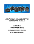
1
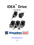
Size 17 Integrated IDEA Drive‐USB Hardware Manual www.haydonkerk.com
All Rights Reserved
9‐2011
1
Table of Contents
Revision History ............................................................................................................. 3
Introduction ..................................................................................................................... 4
Part Numbers .................................................................................................................. 4
Specifications ................................................................................................................. 5
Drawings........................................................................................................................... 6
Connections .................................................................................................................... 8
Basic Wiring ................................................................................................................ 8
Digital I/O Pin Descriptions ..................................................................................... 9
Digital I/O Wiring ...................................................................................................... 10
Digital Output Wiring Examples....................................................................... 11
2
Revision History
Date
Description
July 2011
Initial version
3
Introduction
This manual is intended to provide basic hardware specifications for the Haydon
Kerk size 17 integrated IDEA drive. For detailed information on use and
programming of the drive, please refer to the IDEA Drive User’s Manual,
available at idea-drive.com.
Part Numbers
This manual covers the following part numbers; where (X) is a place holder for
resolution options, (V) is a place holder for coil voltage options, and (XXX) is a
place holder for custom configuration options.
Single Stack Size 17 motors:
•
43HG(X)-(V)-(XXX)
•
43FG(X)-(V) -(XXX)
•
E43HG(X)-(V) -(XXX)
Double Stack Size 17 motors:
•
43MG(X)-(V)-(XXX)
•
43LG(X)-(V) -(XXX)
•
E43MG(X)-(V) -(XXX)
4
Specifications
Attribute
Value
Drive Input Voltage Range
12-48Vdc
Maximum Drive Current (per phase)
2.6Arms (Plus optional 30%
boost during ramping)
Step Modes
Full, Half, ¼, 1/8, 1/16, 1/32,
1/64
Communications
USB (Mini B connector)
Digital I/O Voltage Range
5-24Vdc
Digital Inputs
4
Digital Sinking Outputs
4
Digital Output Maximum Sinking Current
200mA (each)
Digital Input Maximum Current
4mA (each)
Maximum Temperature
70ºC (Measured at heat
sink)
Program Storage Size-Type
85 Kbytes-Flash
Maximum Number of Stored Programs
85, Referenced by 10
character program names
Position counter range
64bit
Type of Ramping
Trapezoidal
Interrupt sources
4 inputs (rising, falling or
both edges), internal
position counter (when
reaching a programmed
position).
5
Drawings
DIMENSIONAL DRAWING - Captive
DIMENSIONAL DRAWING - Non-Captive
6
DIMENSIONAL DRAWING - External
7
Connections
Basic Wiring: To connect power to the drive and control it with the IDEA Drive
User Interface you will need the following:
•
A power supply, 12-48VDC.
•
A PC
•
Power cable ( available from Haydon Kerk p/n 56-1348)
•
USB to Mini B USB cable ( available from Haydon Kerk p/n 56-1346 )
•
10 wire I/O cable (available from Haydon Kerk p/n 56-1352 ). Note: this
cable is only required if the actuator is being communicated to from an
external switch, etc. or the actuator is being programmed to send a signal
to an outside device such as a light. ( or LED )
The following is the proper wiring diagram for the IDEA drive, power supply and
PC. The I/O cable is omitted.
Basic Wiring Diagram
After wiring as shown, turn on power supply and close the switch.
8
Digital I/O Pin Descriptions
Open Collector Output Pin Description
Input Pin Description
9
Digital I/O Wiring
The IDEA drive has four optically isolated inputs and four optically isolated opencollector outputs. The voltage range for these is 5-24VDC. As the outputs are
open-collector, they will need a pull-up resistor tied to the + I/O supply if a high
level voltage is required. The outputs are capable of sinking up to 200mA each.
The inputs can be operated between 5 and 12VDC without any external
components. For voltages above 12 VDC, an external dropping resistor is
required to keep the current between 1mA and 4mA. The equation for the
dropping resistor’s resistance in Ohms is as follows:
((I/O supply voltage – 1.25)/0.0025) – 3000
The power rating of the resistor in watts should be at least:
Resistance * 0.0035 * 0.0035 * 2
Note: The inputs can be used in two ways. They can be connected to logic levels
that swing between I/O supply ground and + I/O supply, or they can be attached
to a switch connected to I/O supply ground. In the second configuration, when
the switch is open, the drive will see this as a logic high, when the switch is
closed, and the input is connected to I/O supply ground, the drive will see this as
a logic low.
Note: When an input is connected to a mechanical switch or relay, a
phenomenon called “bounce” can occur. When the switch contact is almost
closed, several electrical arcs can form. If an input is being used as an interrupt,
each arc will be seen as a rising and falling edge, causing several false interrupts
to trigger. Any input being used as an interrupt source should only be attached to
solid state devices or a switch with debounce circuitry.
10
Digital Output Wiring Examples
I/O Supply Ground (pin 1)
5-24Vdc
I/O Supply + (Pin 2)
LED
Solenoid
Pullup Resistor
Output 1 (Pin 7)
Output 2 (Pin 8)
Output 3 (Pin 9)
Digital signal to external device
Output 4 (Pin 10)
Input pin of another IDEA drive
This resistor is only needed when
I/O Supply is above 12Vdc
11