1
MED ASSOCIATES INC.
O P E N FI E L D A C T I V I T Y H AR D W AR E
Power Connections
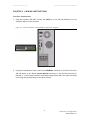
1. Using the included power inverter, connect the +6V DC connector on the back of the DIG-
729 USB device to a standard wall outlet.
Figure 2.4 – Connect DIG-729USB to Wall Outlet
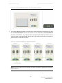
2. Use the power cable to connect the connector on the left side of the ENV-520 Controller to
any available connector on the front of the SG-506 Regulated Power Supply. If the system
includes a sound-attenuating cubicle (SAC), the cables should be run through the grommet
plate on the side of the SAC.
Figure 2.5 - Connect ENV-520 to SG-506
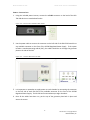
3. It is important to remember to supply power to each chamber by connecting the connector
on the left side of each ENV-520 to any available connector on the front of the SG-506
Regulated Power Supply. The SG-506 can accommodate up to eight chambers.
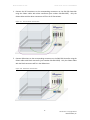
4. Once all the cables have been run, put the top of the grommet plate back in place and
secure the screws.
-7DOC-102 Rev. 1.5 Copyright © 2012
MED Associates, Inc.