1
PRELIMINARY
Document type:
User's Manual (MUT)
Title:
Mod. V874A, 4-channel General Purpose Converter
Revision date:
15/01/2004
Revision:
1
3. VME interface
3.1. Addressing capability
The modules can be addressed in three different ways, specifically:
1. via Base Address;
2. via GEOgraphical address;
3. via Multicast/Chained Block Transfer addressing mode.
3.1.1. Addressing via Base Address
The module works in A32 mode. This implies that the module’s address must be specified
in a word of 32 bit. The Address Modifier codes recognised by the module are
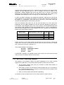
summarised in Table 3.1:
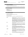
Table 3.1: Module recognised Address Modifier
A.M.
0x2F
0x0F
0x0D
0x0C
0x0B
0x09
0x08
Description
GEO Address
A32 supervisory block transfer (BLT)
A32 supervisory data access
A32 supervisory 64 bit block transfer (MBLT)
A32 non privileged block transfer (BLT)
A32 non privileged data access
A32 non privileged 64 bit block transfer (MBLT)
The Base Address can be selected in the range:
0x00000000
ßà
0xFF0000001
The Base Address of the module can be fixed in two ways:
•
•
by 2 rotary switches;
by writing the Base Address in the ADER register.
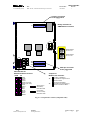
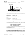
The 2 rotary switches for Base Address selection are housed on the main printed circuit
board (see Fig. 2.3).
To use this addressing mode the bit 4 of the Bit Set 1 Register (see § 3.9) must be set to
0. This is also the default setting.
The module Base Address can be also fixed by using the Ader Register. This register sets
the A[31:24] VME address bits (see § 3.15).
1
bits [23;16] of Base Address are actually “meaningless”, their value is neglected by the V874 A
software; in the examples they are set to 0.
NPO:
00103/99:TAPSy.MUTx/01
Filename:
V874A_REV1.DOC
Number of pages:
67
Page:
21